
300 ICLCR 5 - Pregnant FOCAL - Free user manual and instructions
Find the device manual for free 300 ICLCR 5 FOCAL in PDF.

| Brand | Focal |
| Model | 300 ICLCR 5 |
| Product type | 3-way in-ceiling speaker (ceiling) |
| Sensitivity | 91 dB (2.83 V/1 m) |
| Frequency response | 55 Hz - 28 kHz (±3 dB) |
| Low frequency cut-off | 45 Hz (-6 dB) |
| Nominal impedance | 8 Ω |
| Minimum impedance | 2.9 Ω |
| Recommended amplifier power | 50 - 150 W |
| Dimensions (H x W x D) | 370 x 370 x 195 mm |
| Cut-out diameter | 340 x 340 mm |
| Cut-out depth | 190 mm |
| Net weight | 7.4 kg |
| Tweeter | TNV2 inverted dome in Aluminum/Magnesium alloy |
| Speakers | Flax sandwich cone (flax) |
| Grille | Magnetic attachment, removable and paintable |
| Use in damp environment | Yes (bathroom, kitchen) |
| Adjustments | Adjustment of tweeter level and midrange frequencies (front switches) |
| Installation system | Easy Quick Install tool-free, adapters for ceiling thicknesses 12-54 mm |
| Break-in period | 20 consecutive hours recommended |
| Care and cleaning | Clean with a soft dry cloth. Do not use solvents or chemicals. |
| Safety | Professional installation recommended. Observe connection polarity. Use appropriate cable gauge. |
| Spare parts and repairability | Optional mounting kit, optional fireproof back box. Contact dealer for repairs. |
| Warranty | Legal conformity 2 years (France) |
| General information | Focal 300 Series, French design |
Frequently Asked Questions - 300 ICLCR 5 FOCAL
User questions about 300 ICLCR 5 FOCAL
0 question about this device. Answer the ones you know or ask your own.
Ask a new question about this device
Download the instructions for your Pregnant in PDF format for free! Find your manual 300 ICLCR 5 - FOCAL and take your electronic device back in hand. On this page are published all the documents necessary for the use of your device. 300 ICLCR 5 by FOCAL.
USER MANUAL 300 ICLCR 5 FOCAL
natural_image
Technical line drawing of a three-tiered electronic device with mounting flanges and central hub (no text or symbols)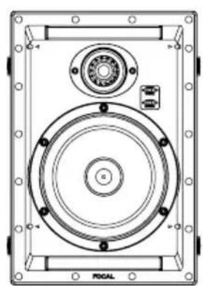
natural_image
Technical line drawing of a mechanical device with circular components and mounting holes (no text or symbols)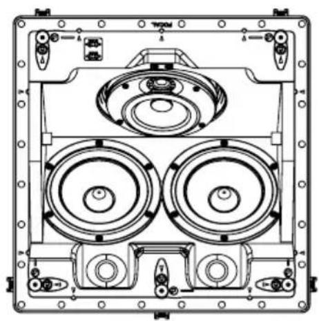
natural_image
Technical line drawing of a mechanical or electronic device with multiple circular components and mounting ports (no text or symbols)Français : page 13
Anglais : page 19
Deutsch : seite 25
Italiano : pagina 31
Español : página 37
natural_image
Interior layout diagram showing a sofa, three speakers, and a wall-mounted speaker room (no text or symbols)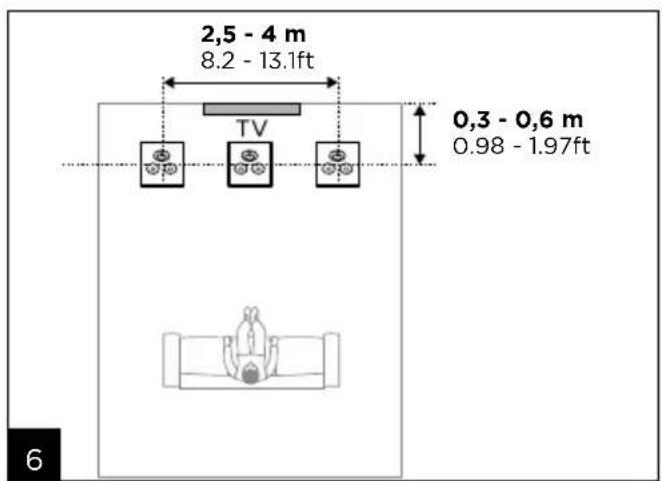
300 SERIES
12 mm (0.5") < A < 32 mm (1.2")
B ≥ 275 mm (10.8")
C ≥ 95 mm (3.8")
A1
natural_image
Simple line drawing of a saw cutting through a square (no text or symbols)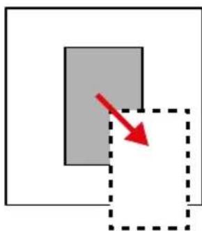
natural_image
Simple diagram showing a gray rectangle with a red arrow pointing to its lower right, enclosed by a dashed square (no text or symbols)A2

natural_image
Illustration of a red megaphone inside a mechanical device, with no visible text or symbols→

natural_image
Illustration of a mechanical device inside a circular frame, featuring a red shield-like object and mechanical components (no text or symbols)x4
natural_image
Two-panel illustration showing a hand holding a red ribbon over a machine, with no visible text or symbols.
A3
300 SERIES
natural_image
Diagram of a speaker inside a display case with red arrows indicating rotation or movement (no text or symbols)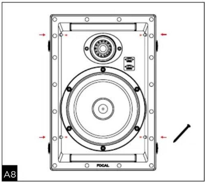
natural_image
Technical diagram of a POCAL speaker enclosure with mounting flanges and central circular components (no text or symbols)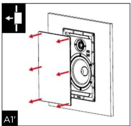
natural_image
Technical line drawing of a mechanical component with a red arrow indicating a specific section (no text or symbols present)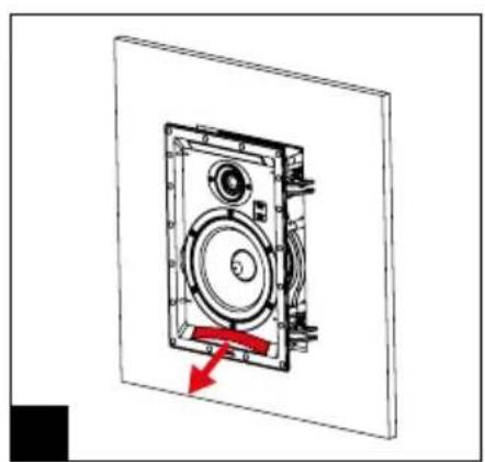
natural_image
Technical diagram of a mechanical device with a red arrow indicating motion or force direction (no text or symbols present)300 SERIES
12 mm (0.5") < A < 32 mm (1.2")
B ≥ 275 mm (10.8")
C ≥ 95 mm (3.8")
B1
natural_image
Simple line drawing of a saw cutting through a rectangular block (no text or symbols)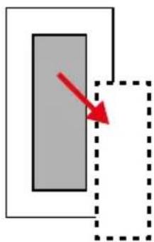
natural_image
Simple diagram with a gray rectangle and a red arrow pointing to it, enclosed by a dashed rectangular border (no text or symbols)B2
natural_image
Diagram of a mechanical device with a red-handled lever and directional arrow, enclosed in a circular frame (no text or symbols)→

natural_image
Illustration of a red cape climbing a machine inside a circular frame (no text or symbols)x4
B3
B5
→
→


300 SERIES
natural_image
Technical diagram of a mechanical device with three circular components and mounting holes, showing directional arrows and component labels (no readable text or symbols)300 SERIES
natural_image
Technical line drawing of a multi-tiered speaker or fan assembly (no text or symbols)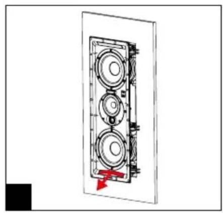
natural_image
Technical diagram of a multi-chamber speaker assembly with a red arrow indicating a component (no text or labels)300 SERIES
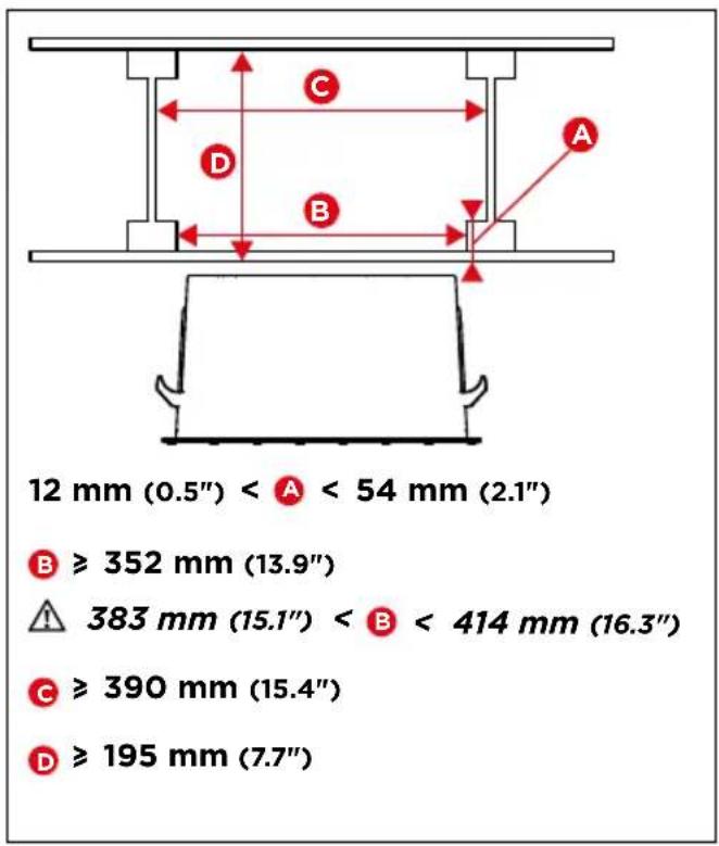
12 mm (0.5") < A < 54 mm (2.1")
B ≥ 352 mm (13.9")
383 mm (15.1") <
B < 414 mm (16.3")
C ≥ 390 mm (15.4")
D ≥ 195 mm (7.7")
C1
natural_image
Diagram of a mechanical device with a lock mechanism and directional arrow (no text or symbols)x5
natural_image
Diagram showing a mechanical device before and after assembly, with red arrows indicating motion direction (no text or symbols)C4
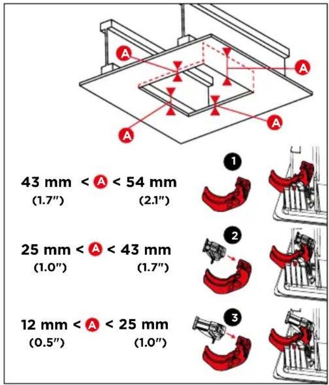
43 mm < A < 54 mm
(1.7")


25 mm < A < 43 mm
(1.0")


12 mm < A < 25 mm
(0.5")
C5
300 SERIES
natural_image
Technical diagram of a mechanical assembly with red arrows indicating motion or force directions (no text or symbols)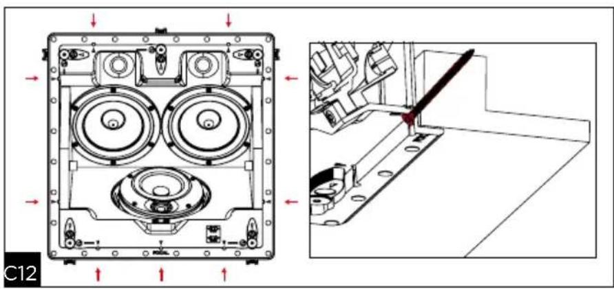
natural_image
Technical diagram of a mechanical assembly with internal components and a close-up view showing a cutting tool (no text or symbols present)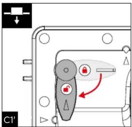
natural_image
Diagram of a computer case with three fans and a central disc, showing red arrows indicating motion or movement (no text or symbols present)300 SERIES
| "-" Position "0" Position "+" Position | ||
| Tweeter -3dB 0dB +3dB | ||
| Medium -2dB 0dB +2dB | ||
D
natural_image
Simple line drawing of a wall-mounted air conditioner unit with a spray can (no text or symbols)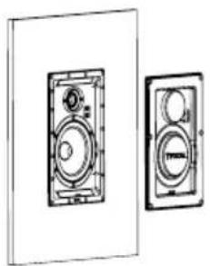
natural_image
Technical line drawing of two speaker or audio unit blocks (no text or symbols)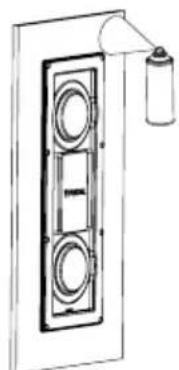
natural_image
Diagram of a double door with circular vented seating and a spray bottle on top (no text or symbols)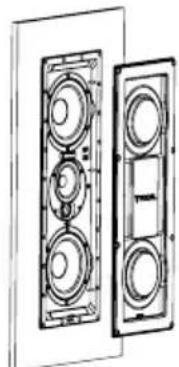
natural_image
Technical line drawing of a multi-chamber electrical enclosure with no visible text or symbolsE
natural_image
Technical line drawing of a mechanical assembly with a central circular component and a hanging cylindrical component (no text or symbols)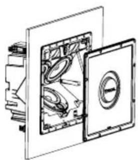
natural_image
Technical line drawing of a mechanical assembly with internal components (no text or symbols)G
F
To facilitate the Focal-JMlab warranty, it is now possible to register your product online, at www.focal.com/warranty

Thank you for purchasing a Focal product. Welcome to our High-Fidelity world. Innovation, tradition, excellence and pleasure are our values; our one and only aim is to bring you a sound that is rich, pure and true. To get the most out of your product, we recommend that you read the instructions in this booklet, then store it in a safe place to refer to in the future.
Package contents
- 1 x loudspeaker from the 300 Series range
- 1 x grille
- 1 x acoustic cloth
- 1 x quick start manual
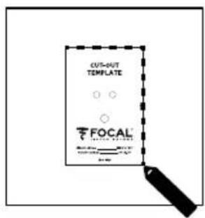
- 1 x cut-out template
- 1 x set of safety instructions and warranty terms and conditions
Key points
Aluminum/magnesium alloy inverted dome TNV2 tweeter the tweeter developed for these products uses Focal's exclusive inverted dome technology, allowing optimal energy transfer and limited directivity. The dome's aluminium/magnesium alloy guarantees exceptional performance in terms of rigidity and dampening, to provide a soft and dynamic treble.
Flax speaker driver cones: all the speaker driver cones of the 300 SERIES range are made using Flax sandwich technology. Flax is an eco-textile with astounding structural properties: it is light, rigid and well-damped, for a greater neutrality of the timbre and better definition.
Magnetically-attached protective grille: easy to fit and improved integration.
OPC ^® (Optimum Phase Crossover): phase optimisation for a more accurate, stable and natural sound image.
Usable in humid environments: such as bathrooms, kitchens, etc.
Optional mounting kit.
Fire-rated back can (optional): ensures compliance with product fire retardancy standards.
Running-in Period
The speaker drivers used in the Integration 300 Series loudspeakers are complex mechanical assemblies which need a break-in period to operate at their best and to become acclimatised to the temperature and humidity of your environment. This break-in period varies depending on the conditions in question and may take several weeks. To reduce this time, we recommend operating your loudspeakers for about 20 consecutive hours. Once the loudspeakers' characteristics have totally stabilised you will be able to enjoy your Integration 300 Series loudspeakers' performance to the full.
Pre-installation wiring
You can only install your speakers once you have wired them up. Make sure you leave enough cable length to be able to connect your product with ease (approximately 50cm). We recommend using a cable with a marker to ensure the polarity of the speaker drivers is respected (+/-). Choose good quality cables with a cross-section appropriate for their length: your dealer will be able to advise you.
Choosing an amplifier
It is not an excess of amplifier power that can damage your loudspeakers and drivers, but rather a lack of power. In fact, if the volume is too high, the amplifier saturates and generates parasite signals that may destroy the tweeter. The dynamic capacity and definition of Integration 300 Series loudspeakers are high enough to reveal the strengths and weaknesses of whatever amplifier is connected to them. Your dealer will be able to guide your choice to suit your tastes and budget.
Installation
Loudspeaker positioning
The loudspeakers in the 300 Series range have been developed to deliver the most faithful sound reproduction, whether they are used for stereo music or home cinema. Nonetheless, a few simple rules should be followed to optimise their performance and to guarantee good tonal balance and a realistic sound image.
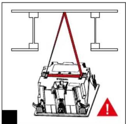
Use in multiple loudspeaker systems (ceiling)
For use in multiple loudspeaker systems (each loudspeaker working independently of the others), the loudspeakers can be installed according to your requirements and the room's architectural constraints. However, take care not to install the loudspeakers too close to a wall or a corner, to avoid excessive low-frequency levels.
Use in stereo systems (ceiling or wall)
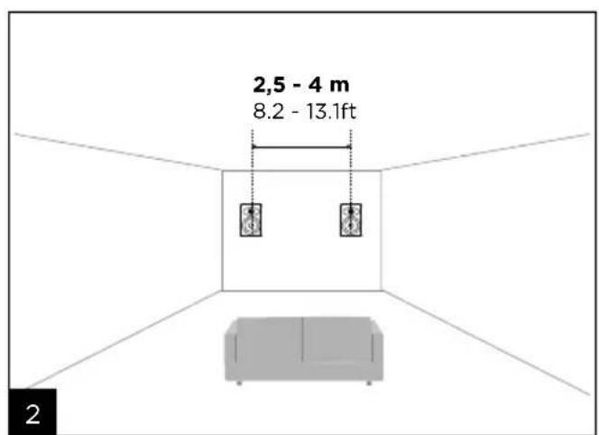
The loudspeakers should be positioned symmetrically, facing the listening area, ideally forming an isosceles triangle with it. The space between the two loudspeakers will be between 2.5m and 4m for a listening area between 3m and 6m (fig. 1). However, it is possible to vary these distances to find an ideal compromise depending on the specific room layout. The loudspeakers should be positioned at the same height and in the same horizontal plane (fig. 2).
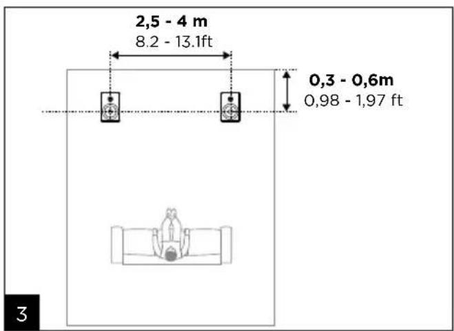
For in-ceiling use, right and left front loudspeakers should be placed in the same horizontal line, between 0.3 and 0.6m from the wall. The space between the right and left loudspeakers should be between 2.5m and 4m (fig. 3).
Use in home cinema systems (ceiling or wall)
• Right, left and central front loudspeakers
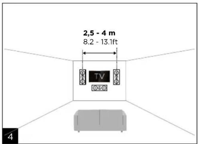
For in-wall use, the right and left front loudspeakers should be placed symmetrically on either side of the screen and at mid-height, facing the listening area, ideally to form an isosceles triangle with it. The space between the two loudspeakers should be between 2.5m and 4m, for a listening area between 3m and 6m, keeping approximately 50cm away from the screen. However, it is possible to vary these distances to find an ideal compromise depending on the specific room layout.
The central loudspeaker should be placed as close as possible to the screen, above or below it, for realistic dialogue reproduction (fig. 4).
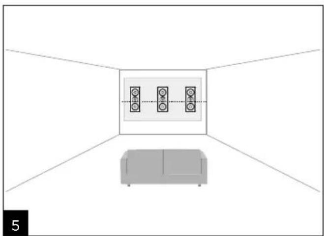
If a micro-perforated (acoustically transparent) projection screen is used, the right and left front loudspeakers and the central loudspeaker should be placed halfway up the screen, in the same horizontal plane behind this screen (fig. 5).
For in-ceiling use, the right and left front loudspeakers and the central loudspeaker should be placed on the same horizontal line, 0.3 to 0.6m from the wall. The space between the right and left loudspeakers should be between 2.5m and 4m (fig. 6).
- Surround-sound loudspeakers for the 5.1 system.
For in-wall use, the surround-sound loudspeakers should be installed on the side walls, slightly behind the listening area (0.5 - 1.5m) and at the same height as the right and left front loudspeakers (fig. 7).
For in-ceiling use, the surround-sound loudspeakers should be installed on the same horizontal line, slightly behind the listening area (ideally 1.5 - 3m) and the space between the right and left loudspeakers should be between 2.5m and 4m (fig 8).
- Surround-sound loudspeakers for the 7.1 system.
For in-wall use, the right and left surround-sound loudspeakers should be installed on the side walls, in the listening area and at the same height as the right and left front speakers. The surround-sound speakers should be installed on the wall behind the listening area and at the same height as the right and left front loudspeakers. The space between the two loudspeakers should be between 2.5m and 4m (fig. 9).
For in-ceiling use, right and left surround-sound loudspeakers should be placed in the same horizontal line in front of the listening area. The surround-sound loudspeakers should be installed on the same horizontal line, slightly behind the listening area (1.5 - 3m) and the space between the two loudspeakers should be between 1.5m and 2.5m (fig 10).
- Atmos® loudspeakers (ceiling)
For a 5.1.2 system, the Atmos loudspeakers should be installed on the same horizontal line, slightly in front of the listening area (0.5 - 1.5m) and the space between the two loudspeakers should be between 2.5m and 4m (fig 11).
For a 5.1.4 system, the front Atmos loudspeakers should be installed on the same horizontal line, slightly in front of the listening area (0.5 - 1.5m) and the space between the two loudspeakers should be between 2.5m and 4m. The rear Atmos loudspeakers should be installed on the same horizontal line, slightly behind the listening area (0.5 - 1.5m) and the space between the two loudspeakers should be between 2.5m and 4m (fig. 12).
Existing installation
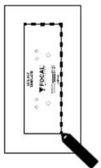
- Before installing the loudspeakers, ensure that the intended positions in the ceiling/wall are free of any obstruction such as air vents or any cables that may interfere with the installation. Use the appropriate tools to help you determine suitable locations.
- Make sure that there is enough space inside the ceiling/wall to install the product.
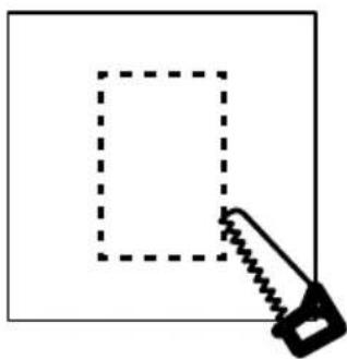
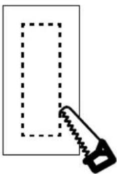
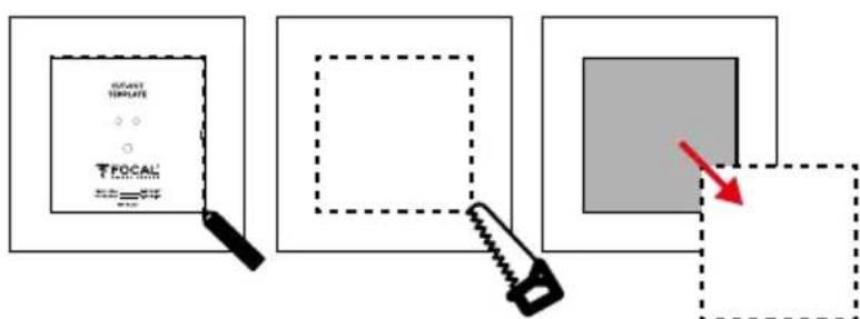
- Trace around the cut-out template provided, onto the existing ceiling/wall. Cut along the traced line with a tool suitable to create an opening in the ceiling/wall (fig. A1, A2 / B1, B2 / C1, C2).
New installation
- Use the optional specific mounting kit
- Wire up the speakers before installing them
Fitting the loudspeaker
Products from the 300 Series range include a loudspeaker and a magnetic grille.
The 300ICLCR5 loudspeaker is supplied with adapters (located close to the corners) allowing it to suit different ceiling depths (12 to 54mm).
Fitting products from the 300 Series range does not require any tools, thanks to the Easy Quick Install system!
300IW6/300IWLCR6
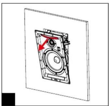
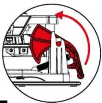
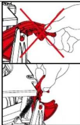
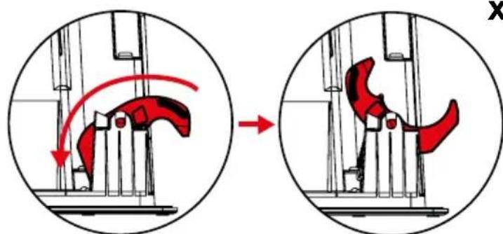
- Lift the mounting feet (fig. A3 / B3)
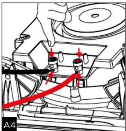
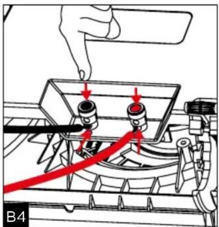
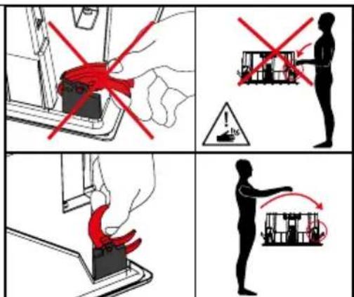
- Connect the pre-stripped loudspeaker wire to the loudspeaker's spring-loaded terminals. It is essential that the connection polarity for each loudspeaker is correct: the cable connected to the "+" terminal on the amplifier must be connected to the red terminal on the loudspeaker. Likewise, the cable connected to the "-" cable on the amplifier must be connected to the black terminal.
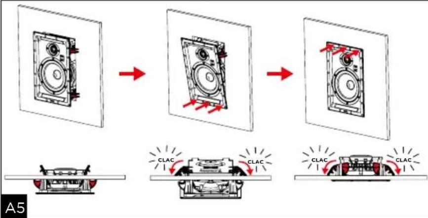
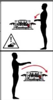
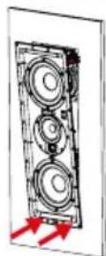
- Insert the product into the wall or ceiling by pressing on each side of the loudspeaker to ensure it is in place (fig. A5 / B5).
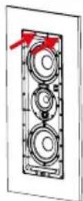
- If necessary, it is possible to add a support screw (up to 4/6). We recommend using screws longer than 8 cm, and inserting them at the points provided for this purpose, marked with a red arrow (fig. A8/B9).
- If required, adjust the treble and mid-range according to the room's acoustics (fig. A6 / B7).
300IWLCR6 : If used as the central loudspeaker, remove the 4 screws from the mid-range and tweeter support, turn the support 90° to line up the tweeter with the "CENTER" marking (fig. B6). Tighten the 4 screws.
300IW6 : Point the tweeter towards the listening area (fig. A6).
- The 300 Series loudspeakers are supplied with an opacifying acoustic cloth. Remove the protective film then attach the cloth to the grille. However, the best audio performance will be obtained without the opacifying cloth.
- The grille can now be fitted. The grille is held onto the mounting frame magnetically, which means you only need to align it with the edge of the mounting frame. (fig. A7 / B8)
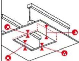
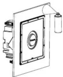
300ICLCR5
- Unlock the safety catch (fig C3).
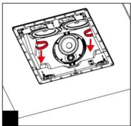
- Lift the mounting feet (fig. C4).
- Measure the ceiling thickness and, if necessary, assemble the suitable adapters (located close to the corners) (fig. C5).
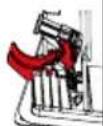
- Install the product securely using a safety sling (fig. C6).
- Connect the pre-stripped loudspeaker wire to the loudspeaker's spring-loaded terminals. It is essential that the connection polarity for each loudspeaker is correct: the cable connected to the "+" terminal on the amplifier must be connected to the red terminal on the loudspeaker. Likewise, the cable connected to the "-" cable on the amplifier must be connected to the black terminal. Stereo image and bass perception will be seriously compromised if these conditions are not respected (fig. C7).
- Insert the product into the wall or ceiling by pressing on each side of the loudspeaker to ensure it is in place (fig. C8), then lock the safety system (fig. C9).
- If necessary, it is possible to add a support screw (up to 9). We recommend using screws longer than 8 cm, and inserting them at the points provided for this purpose, marked with a red arrow (fig. C12).
- Point the mid-range and tweeter support towards the listening area (fig. C10). If required, adjust the tweeter and mid-range levels according to the room's acoustics (fig. C10).
- The 300 Series loudspeakers are supplied with an opacifying acoustic cloth. Remove the protective film then attach the cloth to the grille. However, the best audio performance will be obtained without the opacifying cloth.
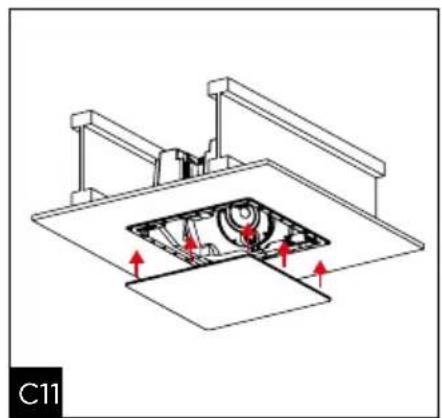
- The grille can now be fitted. It is held onto the mounting frame magnetically, which means you only need to align it with the edge of the mounting frame. (fig. C11)
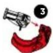
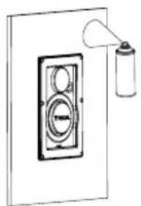
Painting
If you wish, you can paint the grille on your products so that it is coordinated with your environment. We recommend that you firstly remove the grille and paint it using a paint gun. The paint used can be the same type as the paint used on the walls (fig. E / F / G). If you wish to paint the ceiling/wall without disassembling your product, we recommend that you use the protective mask supplied. It is magnetically attached to the mounting frame (fig E / F / G).
Warranty terms and conditions
In the event of a problem, please contact your Focal dealer.
The warranty for France on any Focal equipment is 2 years, non-transferable in the event of resale, from the date of purchase. In the event of faulty equipment, you must send this in its original packaging and at your own expense to the dealer, who will analyse the equipment and determine the nature of the fault. If it is under warranty, the equipment will be returned to you or replaced "carriage paid". Otherwise, you will be offered a quotation for repair.
The warranty does not cover damage resulting from inappropriate use or incorrect connection (burnt out voice-coils, for example).
Outside France, Focal equipment is covered by a warranty for which the terms and conditions are determined locally by the official Focal distributor for each country, in accordance with the laws in force in the region in question.
300IW6/300IWLCR6300IW6/300IWLCR6
300IW6/300IWLCR6300IW6/300IWLCR6
Your Focal-JMlab product was developed and manufactured with high-quality materials and components which can be recycled and/or re-used. This symbol indicates that electrical and electronic equipment must be disposed of separately from normal garbage at the end of its operational lifetime. Please dispose of this product by bringing it to your local collection point or recycling centre for such equipment. This will help to protect the environment in which we all live.
- SERIES
- Package contents
- Key points
- Running-in Period
- Pre-installation wiring
- Choosing an amplifier
- Installation
- Loudspeaker positioning
- Use in multiple loudspeaker systems (ceiling)
- Use in stereo systems (ceiling or wall)
- Use in home cinema systems (ceiling or wall)
- Existing installation
- New installation
- Fitting the loudspeaker
- 300IW6/300IWLCR6
- 300ICLCR5
- Painting
- Warranty terms and conditions
- 300IW6/300IWLCR6300IW6/300IWLCR6
Brand : FOCAL
Model : 300 ICLCR 5
Category : Pregnant