
H2014 - Intercom Emos - Free user manual and instructions
Find the device manual for free H2014 Emos in PDF.


| Product Type | Colour Video Doorphone Set |
| Brand | Emos |
| Model | H2014 |
| Monitor Display | Colour TFT LCD |
| Speaker | Built-in |
| Microphone | Built-in |
| Door Lock Control | Yes (button on monitor) |
| Gate Control | Yes (button on monitor) |
| Ringtone Volume Adjustment | Yes |
| Ringtone Selection | Yes (multiple melodies) |
| Image Brightness Adjustment | Yes |
| Image Colour Adjustment | Yes |
| Speech Volume Adjustment | Yes |
| Power Supply for Monitor | 230 V AC / 50 Hz via adapter (12 V DC output) |
| Door Camera Unit Power | Supplied via cable from monitor |
| Remote Access | Via VDP app (iOS/Android) |
| Wi-Fi Requirement | 2.4 GHz network |
| Recommended Cable | FTP CAT.5 or CAT.6 (up to 50 m) |
| Package Contents | Monitor, mounting frame, door camera unit, screws |
| Maintenance | Wipe with damp cloth (power off) |
| Safety Precautions | Avoid high temperature, humidity, direct sunlight; do not disassemble |
Frequently Asked Questions - H2014 Emos
User questions about H2014 Emos
0 question about this device. Answer the ones you know or ask your own.
Ask a new question about this device
Download the instructions for your Intercom in PDF format for free! Find your manual H2014 - Emos and take your electronic device back in hand. On this page are published all the documents necessary for the use of your device. H2014 by Emos.
USER MANUAL H2014 Emos
1
flowchart
graph TD
    A["1"] --> B["Monitor"]
    B --> C["User Icon"]
    B --> D["Key Icon"]
    B --> E["Screen Icon"]
    B --> F["Audio Icon"]
    B --> G["Speaker Icon"]
    H["6"] --> I["7"]
    H --> J["8"]
    H --> K["9"]
    H --> L["10"]
    H --> M["11"]
    N["2"] --> O["User Icon"]
    N --> P["Key Icon"]
    N --> Q["Screen Icon"]
    N --> R["Audio Icon"]
2
natural_image
Line drawing of a remote control device and its internal mechanism (no text or symbols)3
GB | Colour Video Doorphone Set
Contents of Delivery
1 monitor
1 mounting frame for the videophone
1 door camera unit
mounting screws
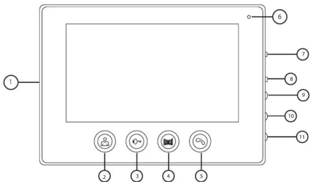
Technical Description of the Monitor
see Fig. 2
Description:
1 – speaker
2 - preview
3 - door lock control
4 - gate control
5 - accept/end call
6 - microphone
7 - ringtone volume
8 - ringtone selection
9 - image brightness
10 - image colour
11 – speech volume
Installation
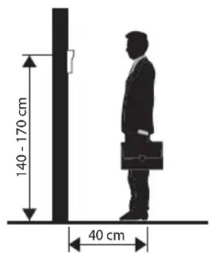
Choosing a Place for Installing the Monitor
Take into account the need for cables when choosing a place to install the device. It is recommended that the device be placed at eye level of the user.
Installation of Mounting Frame
Place the mount on the mounting spot, mark out the locations for mounting holes and drill them into the wall. Sufficient space must remain in the centre of the mount for cables to the monitor (cable from the camera, power supply cable, etc.). Attach the mount using screws; you can also add wall plugs.
Attaching Cables
Connect the door camera unit to the monitor by plugging the cable into the prescribed terminals on both devices.
Suspending the Monitor
Gently press the monitor to the holder so that the protrusions lock into the openings at the rear of the monitor. Pushing the monitor slightly downwards will fix it in place.
Connecting the Device to Power
Connect the power cable to a network which meets the 230 V/50 Hz parameters of the device.
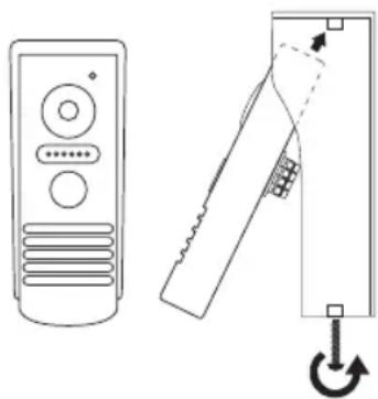
Installation of the Door Camera Unit
see Fig. 3
- Unscrew the screw on the bottom side and slide the door camera unit out from the aluminium hood.
- Choose a suitable place for mounting and attach the hood.
- Attach the connected door camera unit to the covering hood using the enclosed screws.
Mounting the Door Camera Unit onto Plaster
Apply a layer of silicone between the wall and the door camera unit to prevent ingress of humidity. The silicone should be applied on the top and the sides. The bottom side must remain free to allow humid air to flow away.
Parameters of Connection Cables
For distances under 50 m, we recommend a quality FTP CAT.5 cable (optimally CAT.6). At over 50 m, we recommend consulting technical support.
Connect individual conductors in pairs, onto identically numbered terminals on the videophone and the camera unit. The cable shielding must be connected on both sides onto terminal no. 2 (GND).
The connecting cable must not be led along the route of 230/380 V AC cabling.
Operation of the Device
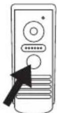



To ring and create an image on the videophone, press the button on the door camera unit shown below.
To accept a call, press this button on the monitor.
To immediately call up the image from the door camera unit, press this button.
To send an impulse to the electrical lock and gate, press one of these buttons.
Operation of Application for Remote Access
1. Downloading the Application
Download the application from Google Play or Apple Store. Name: VDP

VDP
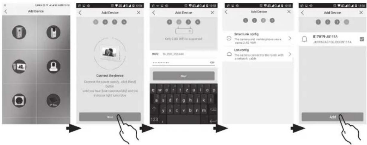
2. Adding a New Device
a) pairing a new device

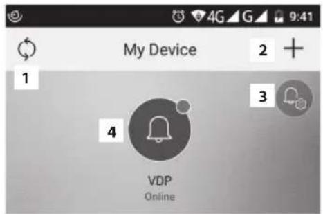
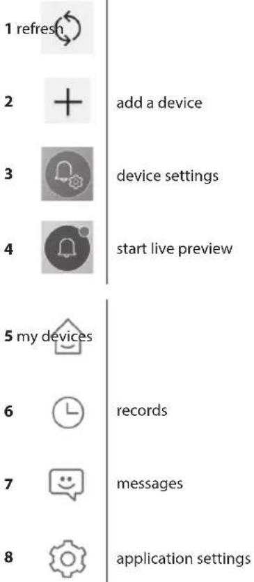
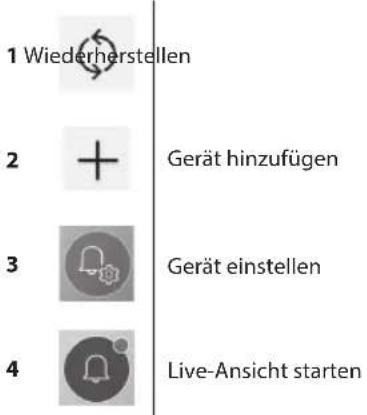
Click this icon on the main screen. Choose the model of the device you wish to connect based on the picture.
b) adding a shared device (device is already added and used by another user)

Click this icon on the main screen. Load the QR code from the display of the user who wants to share access to the device. Access must already be set for the device.
3. Pairing a Device with a Local Network
a) Connect your mobile phone or tablet to the local network. (for Wi-Fi, only 2.4 GHz).
b) After choosing the correct model of connected device according to the image (monitor with camera unit) enter the access information for the network (name of Wi-Fi network and password).
c) Choose the smart config method.
d) After successful pairing, enter name and password (by default: admin/admin).
e) The default password must be changed upon first connection.
4. Unsuccessful Automatic Pairing
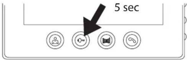
If automatic pairing fails, the device must be reset to factory values by pressing and holding the key button for 5 seconds and disconnecting and reconnecting power supply.
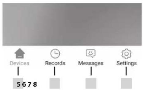
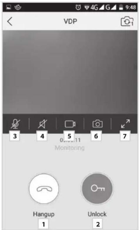
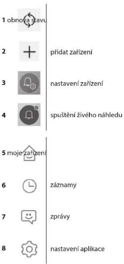
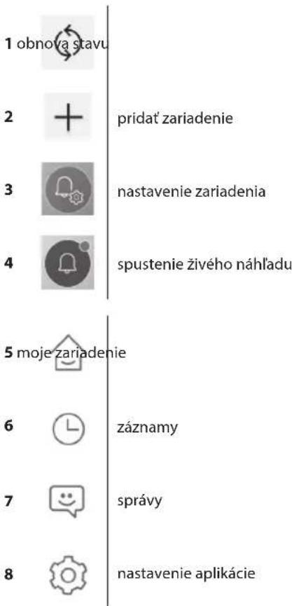
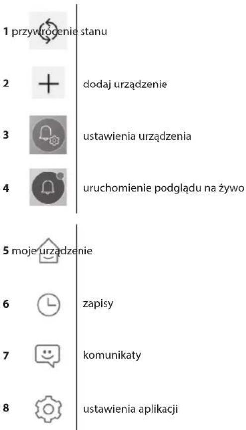
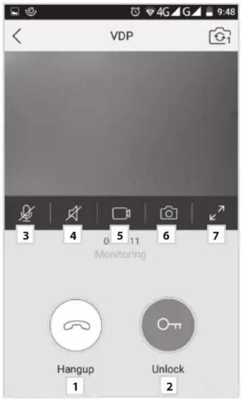
- Meaning of Icons in the Application
1

2

3

4

5

6

7

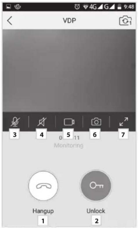
door lock controls
microphone on/off
speaker on/off
start/stop video recording
capture an image
full screen
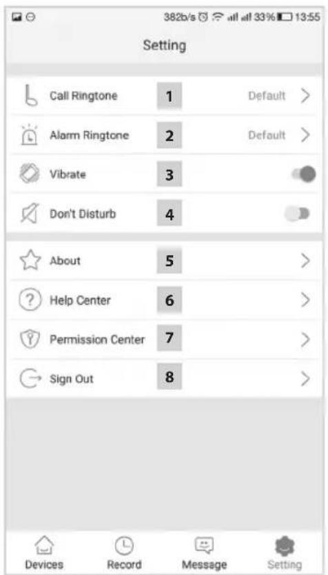
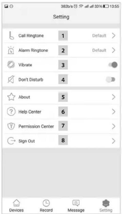
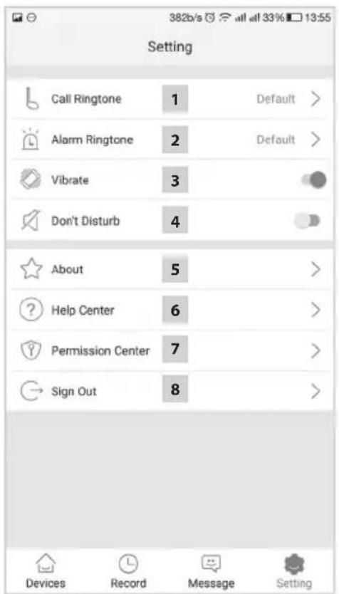
1

2

3

4

5

6

7

8

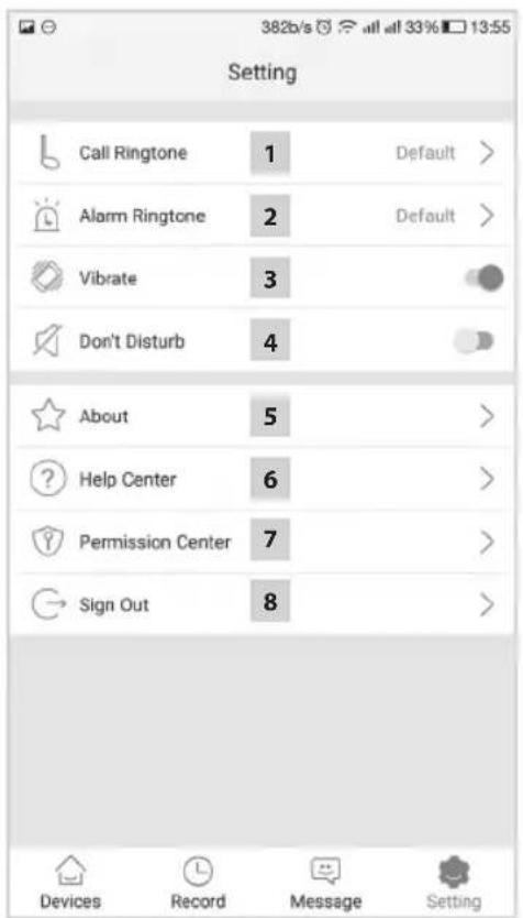
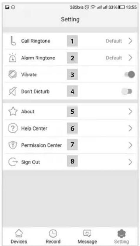
alarm sound selection
vibration
do not disturb (stop notifications)
about the application
help center
setting application functions for running in the background
sign out of the application
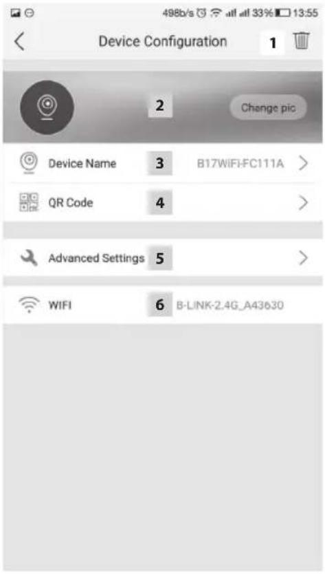
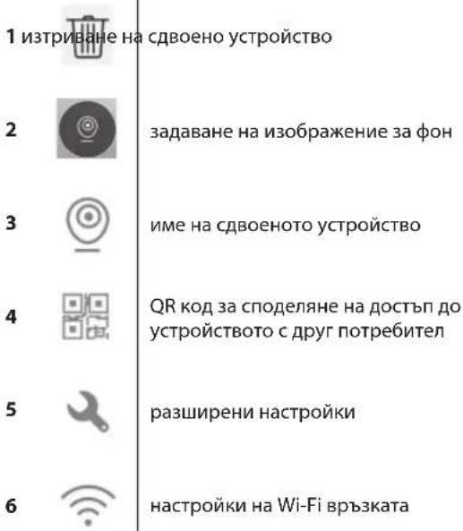
1 delete paired device
2

3

4

5

6

set background image
name of paired device
QR code for sharing access to the device with another user
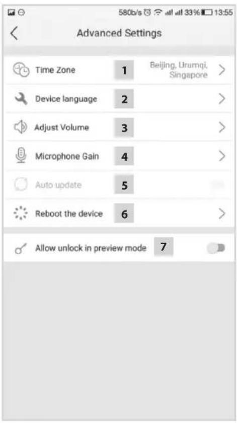
advanced settings
Wi-Fi connection settings
1 time zone settings
2

3

4

5

6

7

application language settings
volume settings for the camera unit speaker
sensitivity settings for the camera unit microphone
automatic system update
device restart
allow lock and gate controls in preview mode
6. Control of the Application
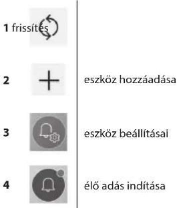
a) Device Settings

access menu change

name device
Here, you can choose a ringtone that will be played upon ringing the bell. Each panel can have a different ringtone to differentiate which input has been activated.

device sharing
After clicking the button, a QR code will be displayed which will allow you to set up the panel on other mobile devices. Simply scan the QR code with another mobile device. This allows simple set-up of the device without the need to go through the entire pairing process again.
b) Preview from Emergency Mode

open preview
Once emergency view is open, you can make video sequence recordings or take photos.

turn recording on/off turn microphone on/off


capture image turn speaker on/off


close preview
c) Incoming Call
During an incoming call the pre-set ringtone will play and information will be displayed on the screen.

receive call take a photo capture image


door lock control end call close call

turn recording on/off
d) Records

enter menu with records delete individual record


enter menu with alarm messages
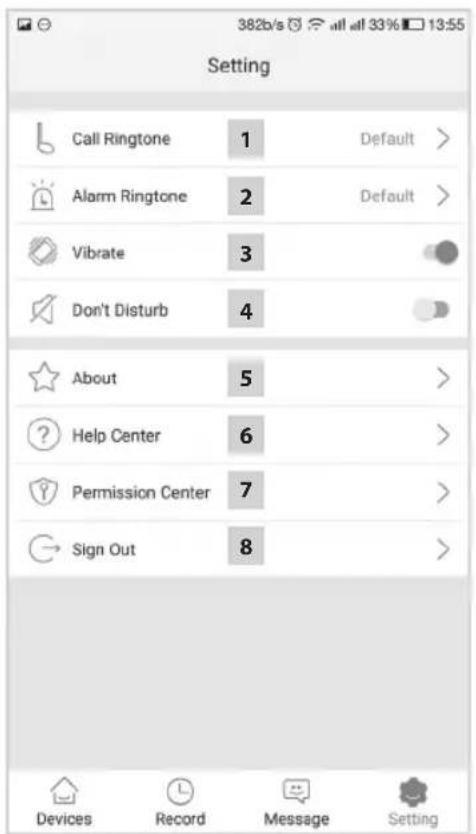
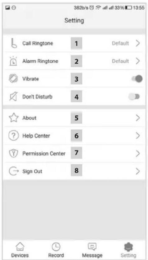
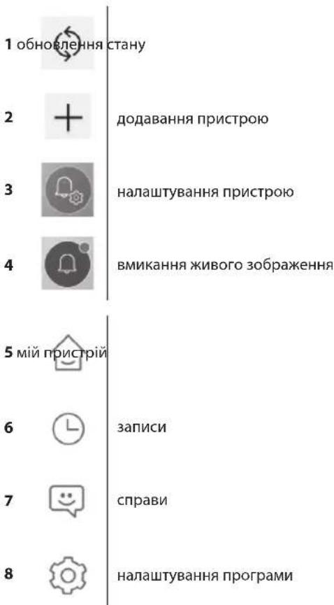
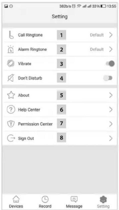
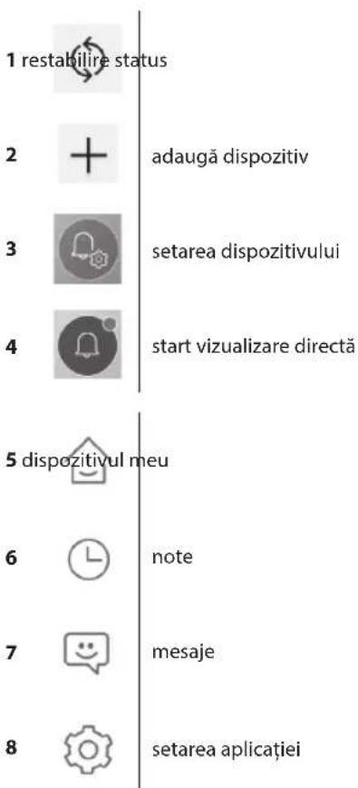
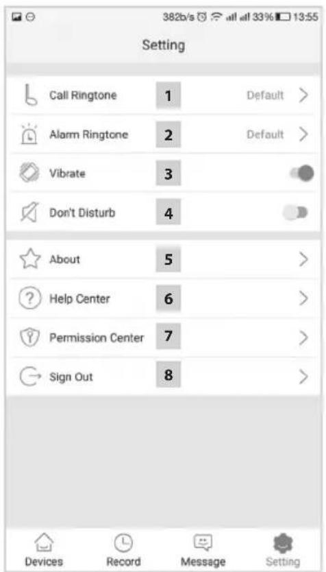
e) Application Settings

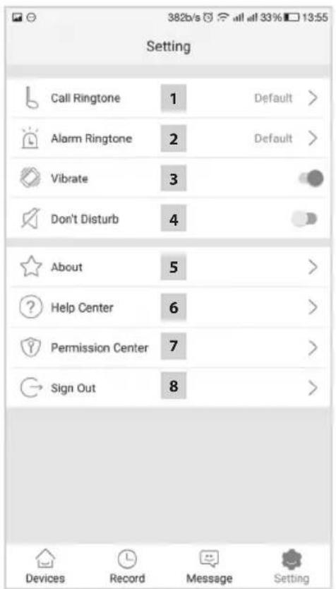
enter the menu about the application


ringtone selection help center

alarm tone selection sign out of the application

vibration
Device Maintenance
The device is low-maintenance. It is recommended, based on the state of the device, to occasionally wipe the device down with a moistened cloth.
Warning!
The device must be disconnected from the power supply before cleaning!
Safety Warnings
- Do not place the monitor in the proximity of TV receivers or into environments with high temperature or humidity.
- Do not touch the TFT LCD display or the monitor by hand and do not disassemble the door camera unit.
- If sunlight shines directly into the lens of the door camera unit, the image on the videomonitor may become illegible.
- Do not subject the device to vibrations or falls.

natural_image
Six black-and-white illustrations showing various tasks: a device, a container, a flask, a person playing a flute, and a hand cleaning a cloth (no text or symbols)FAQ
The device does not work
Check the cables and the connection of the power supply to the network. If you extended the cable from the power adapter, check that the polarity is correct. Measure the adapter with a multimeter. The output voltage on the connector should be 12 V DC (+/- 1V).
The image/sound is not clear, the device does not ring
Remove the monitor or the door panel and connect it using a short cable to eliminate the possibility of a disrupted conductor in the house. Then check the image and sound settings (brightness, contrast, colour, volume).
The lens steams up
This occurs mainly during cold weather, where condensation occurs due to the temperature difference between the wall and the door unit itself. If water condenses on the lens, we recommend thoroughly drying the unit and modifying the installation.
Spontaneous ringing
Spontaneous ringing is caused by moisture entering the camera. Water short-circuits the contacts on the lock switch and the device will start ringing on its own. We recommend dismounting the door unit, drying it thoroughly and spraying it with water repellent for electronics.
High-pitched noise (feedback)
The source of feedback is the scattering of output sound from the door camera unit. The sound feeds back into the microphone where it further amplifies. You can solve this by decreasing the microphone sensitivity and monitor's speaker volume. In door units with adjustable elements, you can do this by turning the potentiometers.
The device does not open the lock
Check that the cabling is intact.
Measure the voltage on the lock terminals using a multimeter. The lock requires a voltage of 12V to trigger. If the value is lower, use stronger conductors for the lock control.
Sudden decrease in microphone sensitivity
Check the cleanliness of the microphone opening, or clean it gently with a thin, blunt object. Be careful not to damage the microphone!
The device does not communicate with the network or cannot be paired
Check the network connectivity, or reset the device (according to point no. 4) and repeat the network pairing process.

Do not dispose with domestic waste. Use special collection points for sorted waste. Contact local authorities for information about collection points. If the electronic devices would be disposed on landfill, dangerous substances may reach groundwater and subsequently food chain, where it could affect human health.
Hereby, EMOS spol. s r. o. declares that the radio equipment type EM-101WIFI (H2014) is in compliance with Directive 2014/53/EU. The full text of the EU declaration of conformity is available at the following internet address: http://www.emos.eu/download.
6. Obsluha aplikace
1 hívás vége
2

3

4

5

6

7

ajtózárvezérlés
mikrofon be/ki
hangszóró be/ki
1
2

3

4

5
6

7

8

dodaj napravo
nastavitev naprave
1 konecklica
2 upravljanje vratne ključavnice
3 vklop/izklop mikrofona
1
2
3
4
5
6
7

8
dodaj uredaj
postavke uređaja
pokretanje slike s kamere
snimke
poruke
postavke aplikacije
1 kraj poziva
2

3

4

5

6

7

kontrole brave vrata
1 brisanje uparenog uređaja
2 postavljanje pozadinske slike
3 | naziv uparenog uređaja
4 QR kod za dijeljenje pristupa uređaju s drugim korisnikom
5 napredne postavke
6 postavke Wi-Fi veze
1 postavke vremenske zone
2 postavke jezika aplikacije
3 postavke glasnoće za zvučnik kamere
4 postavke osjetljivosti mikrofona kamere
5 automatsko ažuriranje sustava
6 ponovno pokretanje uredaja
7 omogućavanje kontrole brave i ulaznih vrata u pregledu slike
6. Upravljanje aplikacijom
a) Postavke uređaja

pristup izborniku
![Add Device Add Device Connect the device Connect the smart subsidy, (New) Custom and you have [short Microsoft City] and the observer light turn into blue Add Add Device Only 2.4G WiFi is supported WiFi: 6.1MHz, 350kHz Add Smart Link config The camera and mobile phone uses a system 2.4G WiFi Lan config The camera connect to the router with a network cable 817WIFI-JU111A JU8RST-MP6LDGLN111A Add](/content/2026/05/849685/images/081ad26aeb4e2e2d7951b960947fb33eaa1772ebec8d9e3a544ade53d6101b3b.jpg)
1 Gespräch beenden
2

3

4

5

6

7

natural_image
Six black-and-white illustrations showing various tasks: a device, a container, a flask, a person playing a flute, and a hand cleaning a cloth (no text or symbols)FAQ
1 baigti skambutj
2

3

4

5

6

7

1
2
3
4
5
6
7

8
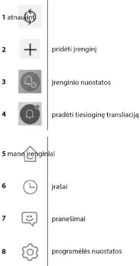
pievienot ierici
ierīces iestatījumi
sākt tiešraidi
ieraksti
ziņojumi
lietotnes iestatijumi
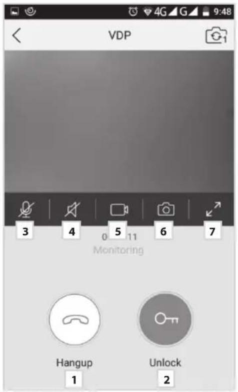
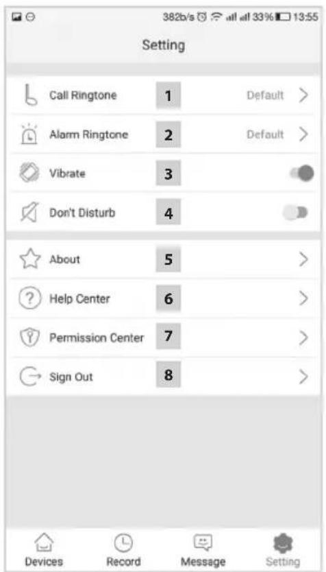
1 beigt zvanu
2

3

4

5

6

7

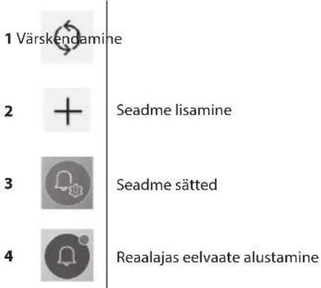
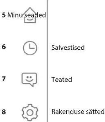
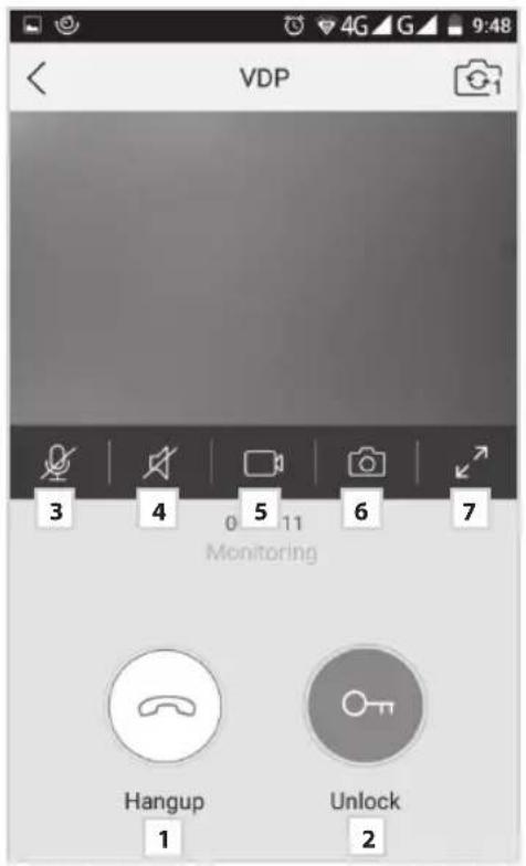
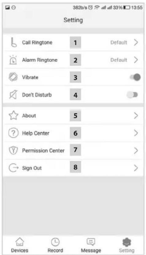
1 Kõne lõpetamine
2

3

4

5

6

7

1
2

3

4

5
6

7

8

1 край на повикване
2

3

4

5

6

7

natural_image
Simple line icons including a musical note, alarm clock, geometric shapes, and a circle (no text or symbols)

- GB | Colour Video Doorphone Set
- Contents of Delivery
- Technical Description of the Monitor
- Description:
- Installation
- Choosing a Place for Installing the Monitor
- Installation of Mounting Frame
- Attaching Cables
- Suspending the Monitor
- Connecting the Device to Power
- Installation of the Door Camera Unit
- Mounting the Door Camera Unit onto Plaster
- Parameters of Connection Cables
- Operation of the Device
- Operation of Application for Remote Access
- Downloading the Application
- Adding a New Device
- Pairing a Device with a Local Network
- Unsuccessful Automatic Pairing
- delete paired device
- 2
- 3
- 4
- 5
- 6
- time zone settings
- 7
- Control of the Application
- a) Device Settings
- b) Preview from Emergency Mode
- c) Incoming Call
- d) Records
- e) Application Settings
- Device Maintenance
- Warning!
- Safety Warnings
- FAQ
- The device does not work
- The image/sound is not clear, the device does not ring
- The lens steams up
- Spontaneous ringing
- High-pitched noise (feedback)
- The device does not open the lock
- Sudden decrease in microphone sensitivity
- The device does not communicate with the network or cannot be paired
- Obsluha aplikace
- hívás vége
- konecklica
- kraj poziva
- brisanje uparenog uređaja
- postavke vremenske zone
- Upravljanje aplikacijom
- a) Postavke uređaja
- Gespräch beenden
- baigti skambutj
- beigt zvanu
- Kõne lõpetamine
- край на повикване
Brand : Emos
Model : H2014
Category : Intercom