
YT-85460 - Generator Yato - Free user manual and instructions
Find the device manual for free YT-85460 Yato in PDF.

| Product type | Electric generator |
| Brand / Model | Yato / YT-85460 |
| Dimensions (L x W x H) | 680 x 510 x 540 mm |
| Weight | 85 kg |
| Rated power (COP) | 4250 W |
| Maximum power (S2 5 min) | 5500 W |
| Output voltage | 230 V AC / 400 V AC (3P+N+PE) / 12 V DC |
| Frequency | 50 Hz |
| Rated AC current | 5.2 A |
| Rated DC current | 8.3 A |
| Engine type | 4-stroke, single-cylinder, air-cooled |
| Displacement | 389 cm³ |
| Engine power | 7.5 kW |
| Rated speed | 3600 rpm |
| Fuel | Unleaded gasoline (octane rating > 93) |
| Fuel tank capacity | 25 L |
| Oil tank capacity | 1.1 L |
| Recommended engine oil | SAE 10W-40 |
| Spark plug | F7RTC |
| Protection class (IP) | IP23M |
| Sound pressure level | 75.0 ± 2.62 dB(A) |
| Sound power level | 93.7 ± 2.62 dB(A) |
| Operating temperature | 0 to +40 °C |
| Maximum operating altitude | 1000 m |
| Grounding | Mandatory for devices requiring an earth connection |
Frequently Asked Questions - YT-85460 Yato
User questions about YT-85460 Yato
0 question about this device. Answer the ones you know or ask your own.
Ask a new question about this device
Download the instructions for your Generator in PDF format for free! Find your manual YT-85460 - Yato and take your electronic device back in hand. On this page are published all the documents necessary for the use of your device. YT-85460 by Yato.
USER MANUAL YT-85460 Yato
natural_image
Exterior view of a YATO 4.25 kW power grid generator with visible circuitry and control panel (no text or symbols on main body)CE
PL DE RU UA LT LV CZ SK HU RO ES FR IT NL GR
natural_image
Interior view of a portable gas generator unit with labeled components (no text or symbols beyond labels)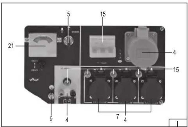
natural_image
Close-up of a hand holding a metallic tool above a circular sink (no text or symbols visible)
natural_image
Close-up of a hand inserting a plastic cylindrical component into a circular opening (no text or symbols visible)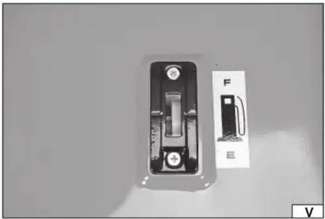
natural_image
Two electrical components: a battery holder and a plug, shown against a plain background (no text or symbols visible)natural_image
Close-up of a hand adjusting a chrome engine component with a wrench (no visible text or symbols)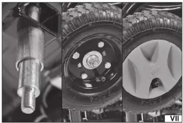
natural_image
Three black-and-white photos showing automotive components: a metallic cylindrical component, a tire wheel with circular hub, and a car wheel (no visible text or symbols)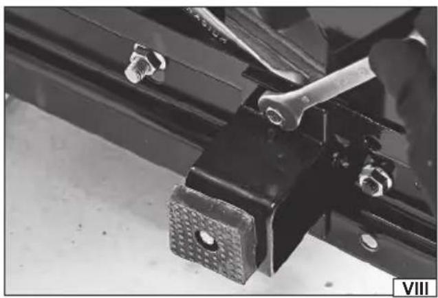
natural_image
Close-up of a mechanical clamp bracket with bolts and a textured base (no visible text or symbols)
natural_image
Close-up of mechanical components with no visible text or symbols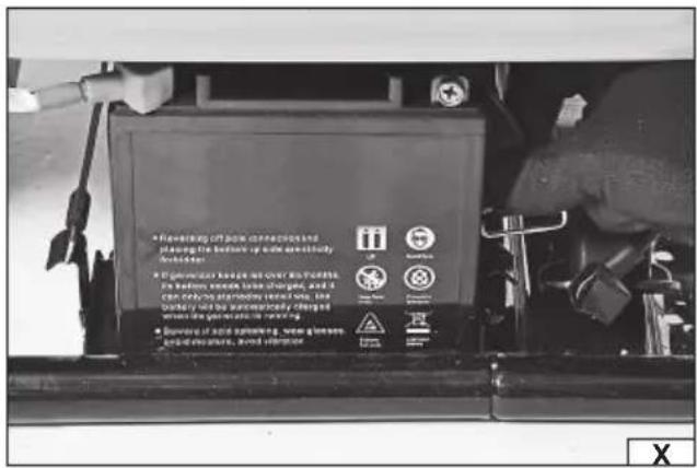
natural_image
Close-up of a mechanical component with a cable inserted, showing a hexagonal bolt and a rectangular block (no visible text or symbols)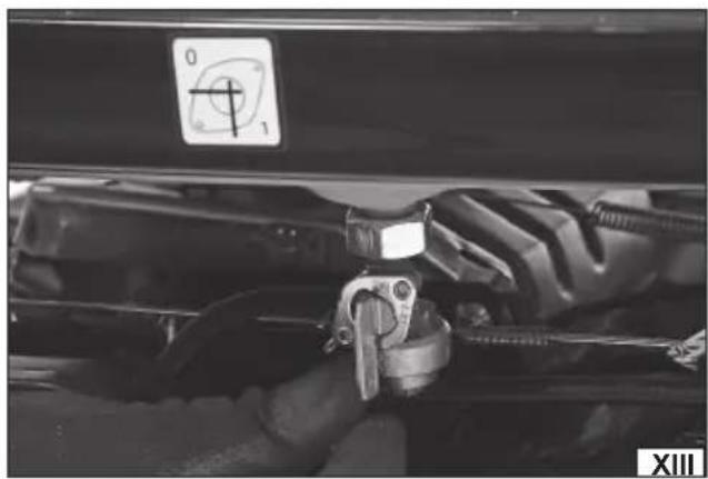
natural_image
Close-up of a mechanical component with a tool and a circular gauge symbol (no readable text or labels)PL DE RU UA LT LV CZ SK HU RO ES FR IT NL GR
natural_image
Interior view of a vehicle showing a black vehicle seat with a white arrow indicating rotation (no text or symbols)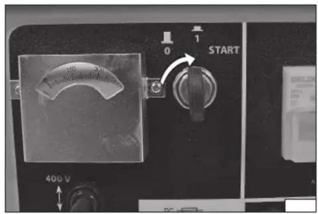
natural_image
Interior view of a portable electric vehicle with visible internal components and hands adjusting parts (no text or symbols)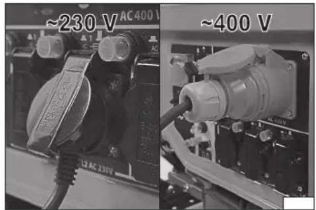
natural_image
Two black-and-white photos showing hands installing or adjusting a device inside a 3D printer (no visible text or symbols)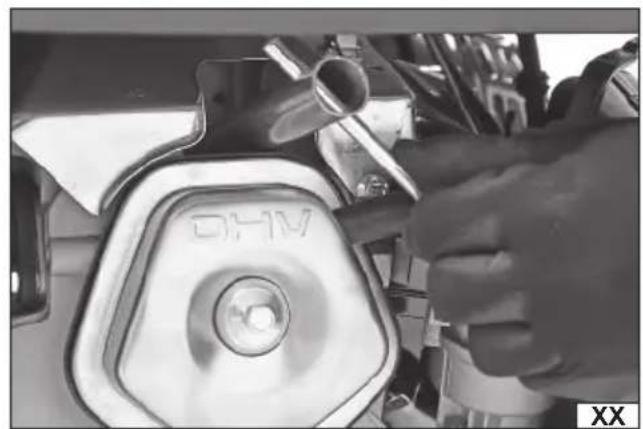
natural_image
Close-up of a hand using a tool to adjust the DHV (DHF) component, no visible text or symbols on the device itself.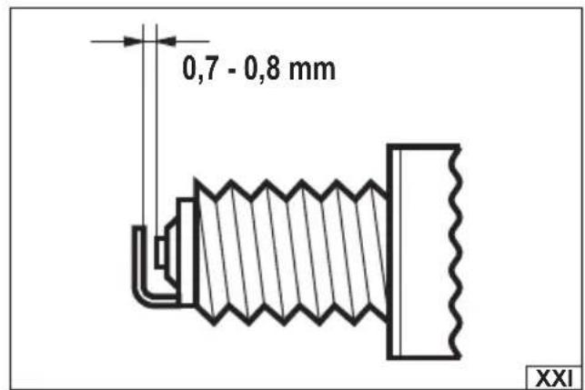
natural_image
Close-up of a mechanical assembly with visible components and wiring (no text or symbols)PL
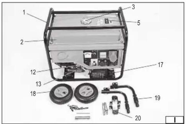
- generator frame
- fuel tank
- fuel fi ller
- power outlet
- engine ON/OFF switch
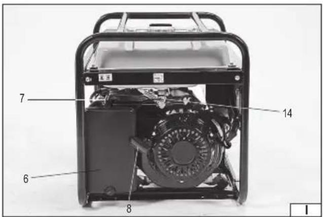
- air filter
- priming accelerator lever
- starter pull cord
- ground terminal
- spark plug
- exhaust pipe
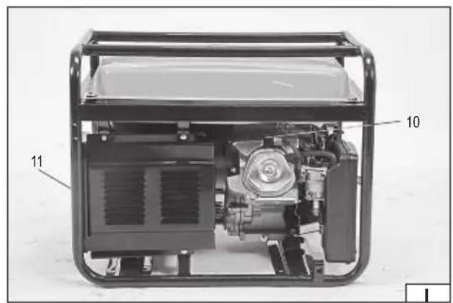
- oil fi ller
- oil drain valve
- fuel supply valve
- overload breaker reset button
- fuel level indicator
- battery
- wheel
- handle
- base
- voltmeter
DE
Read the operating instruction
Mains voltage and frequency
A power generator is an electromechanical device, in which mechanical energy is converted into electrical energy. A generator consists of an internal combustion engine and an electric generator that cooperate. The correct, reliable, and safe operation of the device depends on its proper use, so:
Read and keep the entire manual before the first use of the device.
The supplier shall not be held liable for any damage resulting from failure to observe the safety regulations and recommendations specified in this manual.
ACCESSORIES
The generator is supplied complete and does not require assembly. The generator engine contains oil in the quantity required only for engine maintenance. CAUTION! The oil level must be topped up before first operation. A spark plug wrench is supplied with the generator.
SAFETY INSTRUCTIONS
General safety instructions
Protect children by keeping a safe distance from the generator.
Before starting work, read the generator's markings and the warning labels.
The fuel is explosive and ignites easily. Do not refill fuel while the generator is running. Do not smoke while refilling. Do not refill fuel nearby flames.
Do not spill fuel.
Fuel vapours are hazardous, and fuel preparation and refilling must be carried out in well-ventilated areas.
Some parts of the internal combustion engine can be hot and cause burns. Pay attention to the warnings placed on the generator.
The generator must only be carried using the appropriate handles. Do not touch the generator surface if it becomes hot during operation, this may cause burns.
Fumes and exhaust gases are toxic. Do not use the generator in rooms without ventilation. When used in ventilated rooms, additional measures must be taken to prevent fire and explosion. When using the generator outdoors, ensure that it is not positioned near windows, doors or ventilation inlets. Exhaust fumes can enter the room and cause a hazard.
Read the warning labels and symbols placed on the generator.
Check their meaning with the operating manual.
Electrical Safety
Check the generator and the electrical accessories (including plugs and cables) before use and make sure that they are not damaged.
The generator is not intended to be connected to any other source of electrical energy. It is absolutely forbidden to connect the generator to a 230 V / 50 Hz mains socket.
Protection against electric shock depends on functioning of the fuse specially selected for the generator. If the fuse needs to be replaced, it shall be replaced with a fuse having the same rating and performance characteristics.
Due to high mechanical stresses, flexible cables with hard rubber insulation (according to IEC 60245-4) or equivalent must be used. When using extension cords, make sure that they are suitable for outdoor use. The resistance of the extension cables shall not exceed 1,5 Ω. The total length of the cable must not exceed 60 m for a cable cross-section of 1.5 mm², and 100 m for a cable cross-section of 2.5 mm².
The generator should be grounded if an electrical device which requires grounding will be connected to its socket. Such a device has a power supply cable equipped with a protective conductor. The grounding connection must be carried out by a qualified electrician in accordance with local regulations for the grounding of electrical equipment.
Warning! The location of use of the generator may be subject to local restrictions. Observe the local electrical safety regulations when using the generator.
Warning! The operator must observe the requirements and precautions when retrofitting the generator, depending on the existing protective measures in the plant and the applicable regulations.
Do not overload the generator. Most electrical equipment consumes more power than its rated power during start-up. The power exceeding the rated power of the generator, but not exceeding the maximum power, may not be used for more than 5 minutes in the S2 short-time operation mode. This means that after 5 minutes of operation in this mode, the generator must be stopped and allowed to cool down completely. If the power drawn from the generator does not exceed its rated output, the generator may operate in S1 continuous operation mode.
It is not recommended to use splitters connected to the generator socket. However, if such devices are used, the power demand of all consumers connected to the generator must be summed up. The sum of the power demand of the consumers must not exceed the rated power of the generator.
Operational safety
The generator must stand on a flat, level, hard and stable surface. Provide at least 1 meter of free space around the generator when it is running.
The generator must reach its rated engine revolutions before connecting the electrical consumer. Before switching off the generator, turn off the electrical consumer, if the consumer has moving parts, wait until they have come to a complete standstill and then unplug the consumer's power cord from the generator socket.
The maximum engine's speed of revolution must not be exceeded. If the maximum engine's speed of revolution is exceeded, the generator can be damaged and operators can be injured.
The generator must not be stored or used in a damp or electrically conductive environment (e.g. on metal surfaces).
Do not expose the generator to precipitation. Do not use a generator that is exposed to precipitation.
The generator is not intended for use in potentially flammable or explosive atmospheres.
The gases and exhaust fumes are hot enough to ignite certain materials. Do not use the generator near combustible materials.
The generator must not be used if any damaged or destroyed parts are noticed.
Do not leave the generator in operation unattended or under the care of minors or persons who have not been trained in the operation of the device.
The generator must be switched off immediately if the following symptoms are noticed:
- changes of the engine's speed of revolution,
EN
- overheating of the devices connected to the generator,
- sparking,
- smoke or flames coming out of the device,
- unwanted vibration.
The fuel feed system must be checked periodically. If you notice leaks, have the unit repaired by an authorised servicing centre.
Wait until the engine of the unit has reached its rated engine revolutions before connecting electrical equipment.
All repairs should only be carried out by an authorised servicing centre.
Do not allow fuel to run out while the engine is running!
Do not cover the ventilation inlets and outlets. Even when the generator is not running.
Before transporting the generator, it is necessary to empty the fuel tank.
PREPARING THE MACHINE FOR OPERATION
CAUTION! The checking procedure must be carried out on the generator before each start-up.
WARNING! The generator is supplied with only a small amount of oil in the gearbox. The oil must be topped up before the generator's first operation. Check the oil level regularly and top up if necessary. Starting the generator without oil or with too little oil in the gearbox will cause irreparable damage to the engine.
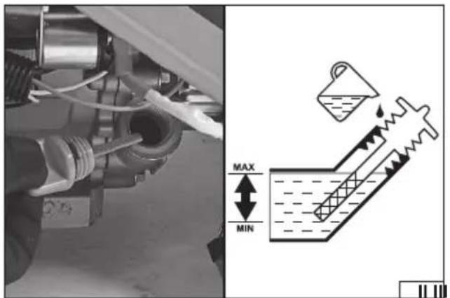
Checking the oil level
Twist off the oil filler cap. The oil filler cap has a dipstick attached. The oil level should be between the lower and upper limit marks on the dipstick. If necessary, add oil to the level indicated in Figure (II).
Use four-stroke premium engine oil with the viscosity class shown in the product specifications table.
Close the oil filler by twisting on the cap.
Caution! Put the power generator on a flat and level surface before adding oil. If the power generator is off level, move it to a flat and level surface and wait at least 30 minutes for the oil level to stabilize.
Caution! Add oil through a filling pistol or a funnel. This will reduce the risk of a spill. If spilled, thoroughly wipe off all oil before starting the power generator.
Caution! The power generator features an oil level sensor which will prevent ignition when the oil level is too low. If the power generator fails to start, check the oil level.
Refuelling
93-octane unleaded petrol or better is recommended.
Use four-stroke engine fuel and oil which are free from solid impurities. Premium quality products are recommended. They will extend the service life of the engine.
Do not refuel above the maximum level marked on the fuel tank. Leave a headroom of air between the fuel level and the top of the fuel tank.
Refuel with a fuel pump and/or a funnel. This will reduce the risk of a spill. If spilled, thoroughly wipe off all fuel before starting the power generator.
Never smoke when refuelling.
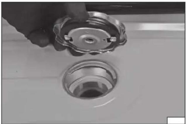
Open the fuel filler cap counter-clockwise to open. Remove the cap from the fuel filler. The cap has two bosses which need to
engage the two locating grooves in the fuel filler's neck (III). Close the fuel filler by twisting on the cap clockwise. This is the only way to open and close the fuel filler cap.
A fuel filter (IV) is inside the fuel filler to retain some of the solid impurities that may be present in the fuel. Always refuel the fuel tank with the filter installed in the fuel filler.
See the product specifications table for the fuel tank capacity. The tank is equipped with a mechanical fuel level indicator (V). If the indicator is close to the "E" marker, the tank is empty. If the indicator is close to the "F" marker, the tank is full.
Generator grounding
Connect the cable between the grounding system and the power generator to the ground terminal marked on the generator. The power generator must be connected to a grounding system by a person with appropriate electrical qualifications.
Installation of wheels and handles
The generator frame has been adapted for mounting wheels and handles. They are not necessary for proper operation of the generator, but they facilitate the transport of the generator over short distances. Start by fixing the wheel axles with the nuts (VI). Place the spacer sleeves on the generator axle and then the wheel and fix it on the axle with the nut (VII). Place a decorative cap on each wheel. Fix the bases on the other side of the frame by screwing them in place using bolts and nuts (VIII). The bases level the generator after the wheels have been mounted.
Attach the handles to the upper part of the frame, on the base side, using bolts and nuts (IX). Make sure that the handles fold inwards after installation. This saves space when the generator is not being transported.
CAUTION! Infl ate the wheel tyres. Do not exceed the rated pressure indicated on the tyre side. The wheels are only suitable for transporting the generator on foot. Do not attach the generator to any vehicles.
With the preparations for operation complete, you may now start the power generator.
GENERATOR OPERATION
Start-up of the combustion engine
Before starting the power generator, unplug all electrical loads from the power outlets of the power generator.
The generator motor can be started in two ways: by an electric starter powered by a battery or by a manual starter operated by a starter pull cord.
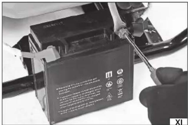
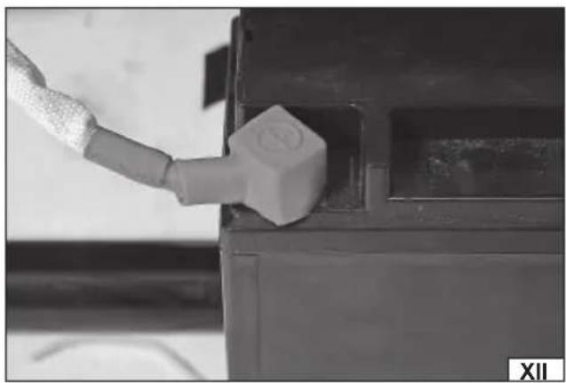
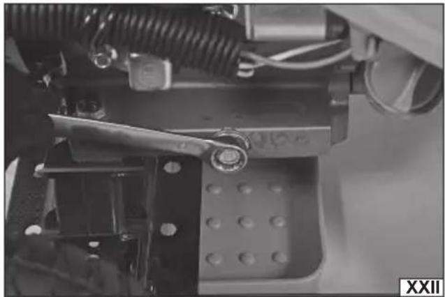
The generator is supplied with a disconnected battery, which prevents accidental starting of the generator, and also slows down the process of battery discharge. The battery should be removed from the base by removing the hooks of the elastic band (X). Slide the cover off the cable clamp, and then fix the clamp to the battery clamp (XI) using a screw and a nut. Push the cover over the cable and battery clamp (XII). Secure the battery to the generator frame using the elastic band.
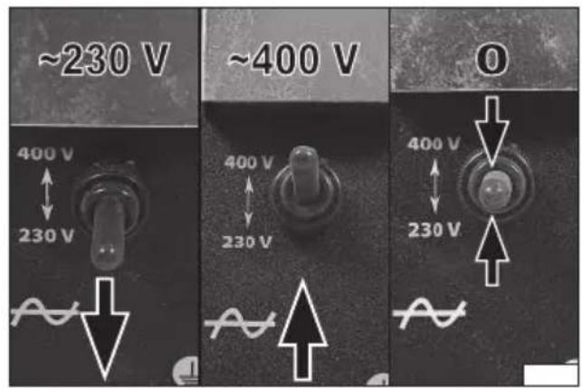
Open the fuel supply valve by rotating it to the "ON" position (XIII). Move the engine switch to the position corresponding to the rated voltage to be used (XIV). The switch has the following
EN
positions: the position marked "230 V" corresponds to the supply of 230 V/50 Hz power sockets, the position marked "400 V" corresponds to the supply of 400 V/50 Hz power sockets. The middle position indicates that the switch is in the off position. Close the throttle by moving the priming accelerator lever to stop at the "OFF" marker (XV).
Turn the electric start key from the "0" position to the "1" position (XVI). If you cannot hear the starter sound, the battery may be discharged. This can happen at the first start-up or start-up after a long period of storage of the generator. If it is not possible to use the electric start, use manual start.
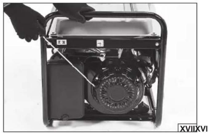
Pull the starter pull cord smoothly several times until you feel the resistance caused by the engine compression, which is when you should pull it vigorously and firmly (XVII).
While holding the handle, let the starter pull cord retract itself in a controlled manner until it is fully inside the power generator housing. Do not release the starter pull cord handle so that it is suddenly retracted into the housing. This can damage the starter. As the engine is heating up, open the throttle gradually by moving the priming accelerator lever gradually towards "ON". Allow the engine to start running smoothly every time you reposition the priming accelerator lever. The rate at which the priming accelerator lever should be reversed depends on the ambient temperature in which you start the engine. The lower the ambient temperature, the slower the lever should be reversed.
The generator is equipped with a voltmeter, which allows to approximately check the voltage taken from the generator.
Connecting electrical loads to the power generator
CAUTION! Do not connect electrical loads with a power rating higher than the rated power output of the power generator. If more than one electrical load is connected, the total rated power of all connected loads must be lower than the rated power output of the power generator.
CAUTION! Verify that the ratings of the electrical loads to be connected match the ratings of the power generator.
CAUTION! The devices cannot be powered by the 230 V sockets and the 400 V socket at the same time. Only the 230 V sockets or the 400 V socket can be used at the same time.
Start the engine according to the procedure in "Start-up of the combustion engine".
Make sure that the electrical loads to be connected are switched off. Lift the socket cover and plug in the receiver power cable to the generator socket.
Switch on the connected electrical load.
Caution! If more than one electrical load is connected, switch on each next load when the previous load starts running steadily (i.e. at the rated speed, temperature, etc.).
Each of the sockets has its own overload breaker. If the power output is overloaded by an excessive power output consumption, the socket of the generator is isolated from power but the engine will keep running. Overload is indicated by the operation of the fuse. In the case of 230 V and 12 V sockets, it happens when the fuse is "blown", and in the case of 400 V sockets, it happens when the fuse switches to the lower position. In such a case, switch off all the receivers, which were indicated as overloaded, connected to the generator using the switch, unplug the receiver from the generator socket, wait until the generator circuits cool down, and press the overload breaker reset button. If the activation of the fuse repeats, switch off all the receivers connected to the generator using switches and then disconnect their cables from the generator sockets. Stop the generator and wait for it to cool down. Make sure that the total rated power of all connected electrical loads does not exceed the rated power output of the power generator. Disconnect the electrical loads as required. Check if the air intake and/or the air vents are obstructed. Check the power generator's vicinity for anything which might obstruct the air intake / air vents.
After checking, press / adjust the fuses and then restart the generator according to the start procedure.
CAUTION! The overload breaker may trip when switching on a connected electrical load; most electrical power loads start with a power consumption exceeding their ratings. If the electrical power load is not defective, it might not be compatible with the power generator's output.
CAUTION! If a DC socket is used with AC sockets at the same time, the power of the receiver connected to this socket should also be taken into account when adding up the power.
Stopping the engine
Switch off the electrical load connected to the power generator. Unplug the electrical load power cables from the power generator. Turn the engine switch to the O - off position.
Wait until the engine stops.
Close the fuel supply valve by rotating it to "OFF".
CAUTION! Should it be necessary to shut down the engine immediately in the event of an emergency, move the engine switch to the O - off position.
Operation at high altitude
The carburettor installed in the generator has been designed for correct operation at an altitude not higher than specified in the technical data table. If you need to work at a higher altitude, contact an authorized servicing centre to modify the carburettor. Even after modification of the carburettor, it is expected that the power of the combustion engine will decrease, and consequently the generator's power will decrease by 3.5 % for every 300 meters of altitude increase above the limit given in the table. The power drop will be greater when using a generator without a modified carburettor. The decrease in power is due to the dilution of air as sea level altitude rises.
MAINTENANCE AND OVERHAUL
During the warranty period, the user cannot disassemble the device or replace other assemblies or components than those listed below, as this will invalidate the warranty. Any irregularities found during the check or the operation signal the need for repair to be done at the servicing centre.
After work has been fi nished, clean the housing, ventilation slots, switches, additional handle grip and guards using e.g. a jet of air (pressure not more than 0.3 MPa), or a brush or dry cloth without the use of chemicals or cleaning liquids. Clean the tools and holders with a clean, dry cloth.
Scheduled Inspections
Periodic inspection and maintenance of the following generator assemblies must be carried out.
EN
CAUTION! All maintenance must be carried out with the machine switched off and not running. It is also necessary to disconnect all electrical equipment from the generator.
CAUTION! If a service operation is not described below. This means that the device must be serviced by a specialist servicing point for this purpose.
CAUTION! Where solvent is used for cleaning, avoid contact of the solvent with skin and eyes. Use personal protective equipment.
| Component | Notes | Before each start-up | After the first month of operation or the first 20 hours of operation | Every 3 months or after 50 hours of operation | Every 12 months or after 100 hours of operation |
| Engine gearbox oil level | Check X | ||||
| Replace X X | |||||
| Air fi Iter | Check X | ||||
| Clean X X(*) | |||||
| Spark plug | Cleaning. Replace, if necessary. | X | |||
| Fuel fi Iler fi Iter | Check. Replace, if necessary. | X | |||
| Fuel system | Check for tightness and damage. | X | |||
| Replace Every two years | |||||
| Removal of carbon deposits | Check more frequently if necessary | X | |||
| Engine | Cleaning and adjustment of valves and cylinders | Every 125 hours | |||
(*) A higher frequency is recommended in case of use in dusty environments.
It is recommended to replace the fuel tank every three years. If any leaks are detected in the fuel system, it is forbidden to use the generator.
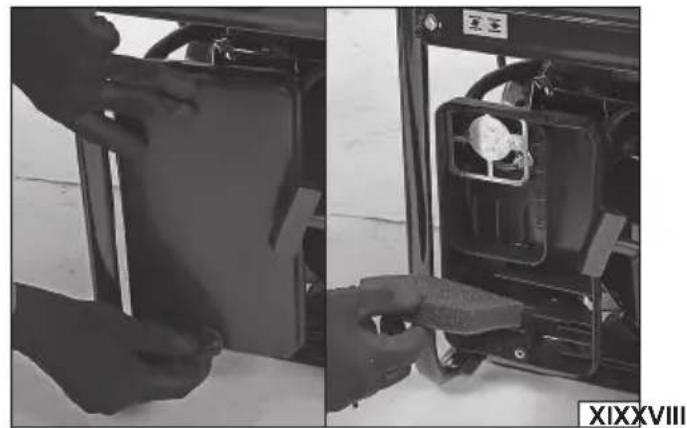
Maintenance of the air fi Iter (III)
CAUTION! Do not operate the power generator without a correctly installed air filter or with a defective air filter. Otherwise the combustion engine may aspirate impurities that would normally settle on the air filter. Impurities can lead to malfunctions or, ultimately, cause a failure of the power generator.
Release the knob and remove the air filter cover. Remove the filter and clean it in a non-flammable solvent, then thoroughly squeeze out the solvent.
Soak the air filter with clean engine oil and squeeze it out so that the filter remains slightly moist only.
Install the air filter in place and close the air filter cover with the knob.
Maintenance of the spark plug
Disconnect the cable from the spark plug.
Remove the spark plug with the spark plug wrench (XX).
Use a wire brush to clean carbon deposits off the electrodes (so-called combustion deposits).
Check the distance between the electrodes from 0.7 mm to 0.8 mm. (XXI)
If burned electrodes or the ceramic casing is broken, replace the spark plug with a new one.
Screw in the spark plug. Connect the cable to the spark plug.
Changing the engine oil
CAUTION! It is best to change the engine oil as soon as the engine has come to a standstill. Then the oil is the thinnest and will flow out of the engine gearbox the fastest.
Care must be taken when changing the oil. As soon as the engine stops, the oil is hot and can cause burns.
Each oil tank has a drain opening. Place a container with a capacity greater than that of the oil tank underneath the drain opening.
Unscrew the drain valve (XXIII) completely using a wrench. Allow the oil to flow into the tank and then screw in the drain valve using a wrench. Wipe any oil residue dry.
Top up the oil according to the procedure described under "Checking the oil level".
CAUTION! Dispose of used motor oil in accordance with the local regulations. It is forbidden to spill engine oil into the sewer system.
Maintenance of the fuel filler filter
Remove the fuel filler cap. Take out the fuel filler filter. Clean the fuel filler filter using extraction petrol. Dry with a soft, clean cloth. Install the filter in the filler opening. Close the fuel filler cap.
CAUTION! The filter walls are made of fine mesh. Care must be taken during maintenance to ensure that they are not damaged. If the filter is damaged, replace it with a new one that is free of damage before resuming operation.
Storage of the power generator
If you need to store the power generator for a short time (less than 10 days), stop the engine, unplug all electrical loads, and close the fuel supply valve.
If the power generator will be stored for more than 10 days, follow the procedure below.
Move the engine switch to the O - off position.
Remove the fuel filler cap and drain fuel from the tank with a suitable pump. Close the fuel filler cap.
Start the engine according to the procedure in "Start-up of the combustion engine".
Do not plug in any electrical loads. Let the engine running until it stalls to stop without fuel. The running time will depend on how much fuel remains in the fuel tank and the fuel supply lines. Move the engine switch to the O - off position.
Close the fuel supply valve by rotating it to "OFF".
Remove the spark plug from the cylinder. Add a table spoon of engine oil through the empty spark plug port on the cylinder. Use the engine oil with the viscosity listed in the product specifications table.
Screw in the spark plug. Pull the starter pull cord so that the engine cranks through a few revolutions and the cylinder piston is lubricated. Stop pulling the starter pull cord when you feel the compression.
Regardless of the storage time, you should always:
Clean the outside of the generator with a soft cloth, brush or
EN
compressed air jet at a pressure of 0.3 MPa or less. Pay particular attention to the permeability of the ventilation slots.
Store the generator in a horizontal position.
Store the generator in a dry, well-ventilated and covered room.
Transporting the generator
WARNING! The generator must always be transported with the combustion engine stopped and the consumers disconnected.
For short distances, e.g. when moving the generator at the point of use, the generator must be transported holding it by the frame. Be careful not to swing or tilt the generator to spill fuel. The generator may be hot, stay cautious to avoid burns.
For longer transport distances, the generator must be prepared for transport according to the procedure described under "Storage of the generator". The generator must be transported in a horizontal position. Secure the machine with belts to prevent it from tipping over during transport.
Spare parts
For a detailed list of spare parts for the appliance go to the "Download" section in the Product tab on the TOYA SA website: toya24.pl.

This symbol indicates that waste electrical and electronic equipment (including batteries and storage cells) cannot be disposed of with other types of waste. Waste equipment should be collected and handed over separately to a collection point for recycling and recovery, in order to reduce the amount of waste and the use of natural resources. Uncontrolled release of hazardous components contained in electrical and electronic equipment may pose a risk to human health and have adverse effects for the environment. The household plays an important role in contributing to reuse and recovery, including recycling of waste equipment. For more information about the appropriate recycling methods, contact your local authority or retailer.
TECHNICAL PARAMETERS
| Generator type YT-85460 | ||
| Parameter Measure Unit Value | ||
| ELECTRIC GENERATOR | ||
| Rated voltage | [V] A.C. 230 | |
| [V] A. C. 400 (3P/N/PE) | ||
| [V] D.C. 12 | ||
| Rated frequency [Hz] 50 | ||
| Generator rated power COP [W] 4250 | ||
| Maximum power (S2 5 min) [W] 5500 | ||
| Power factor 1.0 | ||
| Rated current (A.C.) [A] 5.2 | ||
| Rated current (D.C.) | [A] 8.3 | |
| Electric insulation class | I | |
| Degree of protection of the housing (IP) | IP23M | |
| Performance class | G1 | |
| Quality class | A | |
| MECHANICAL ENGINE | ||
| Type | CP188F | |
| Number of cylinders | 1 | |
| Number of strokes | 4 | |
| Fuel type | Unleaded petrol | |
| Type of oil | [SAE] | 10W-40 |
| Fuel consumption (at 75% load) | [l/h] | 4.27 |
| Engine capacity | [cm3] | 389 |
| Rated power | [kW] | 7.5 |
| Rated speed | [min-1] | 3600 |
| Idling speed revolutions | [min-1] | 1800 ± 100 |
| Cooling | Air cooling | |
| Compression stage | 8.5:1 | |
| Fuel tank capacity | [I] 25 | |
| Oil tank capacity | [I] | 1.1 |
| Spark plug type | F7RTC | |
| DEVICE | ||
| Overall dimensions | [mm] | 680 x 510 x 540 |
| Weight | [kg] | 85 |
| Operating temperature range | [°C] 0 ÷ +40 | |
| Maximum operating altitude | [metres above the sea level] | 1000 |
| Noise level | ||
| Sound pressure Lpa±K | [dB(A)] | 75,0±2,62 |
| Sound power Lw±K | [dB(A)] | 93.7±2.62 |
DE
GERÄTEBESCHREIBUNG
ELEKTROGENERATORA LIETOŠANA
DEKLARACJA ZGODNOŚCI DECLARATION OF CONFORMITY DECLARATIE DE CONFORMITATE
0924/YT-85460/EC/2024
We declare and guarantee with full responsibility that the following products:
meet requirements of the following European Standards / Technical Specifications:
and fulfil requirements of the following European Directives:
Serial number: concern all serials numbers of item(s) mentioned in this declaration
The person authorized to compile the technical file:
DEKLARACJA ZGODNOŚCI DECLARATION OF CONFORMITY DECLARATIE DE CONFORMITATE
0924/YT-85460/EC/2024
We declare and guarantee with full responsibility that the following products:
meet requirements of the following European Directive: 2000/14/EC
Conformity assessment procedure:
Manufacturer quality-control system, examination of the manufacturer's technical file and periodical inspection by notified body
Measured sound power level on an equipment representative for this type:
Guaranteed sound power level for this equipment:
conformity and references of the other Community Directives applied:
