PMK 1100 A1 - Compressor PARKSIDE - Free user manual and instructions
Find the device manual for free PMK 1100 A1 PARKSIDE in PDF.

User questions about PMK 1100 A1 PARKSIDE
0 question about this device. Answer the ones you know or ask your own.
Ask a new question about this device
Download the instructions for your Compressor in PDF format for free! Find your manual PMK 1100 A1 - PARKSIDE and take your electronic device back in hand. On this page are published all the documents necessary for the use of your device. PMK 1100 A1 by PARKSIDE.
USER MANUAL PMK 1100 A1 PARKSIDE
PORTABLE COMPRESSOR PMK 1100 A1
KOMPRESSOR TRAGBAR PMK 1100 A1 COMPRESSEUR PORTABLE PMK 1100 A1
IE MTGB NI CY
PORTABLE COMPRESSOR
Translation of the original instructions
BEFR CH
COMPRESSEUR PORTABLE
Before reading, fold out the page with the images and familiarise yourself with all the features of the device.
DE AT CH
GB/IE/NI/CY/MT Translation of the original instructions Page 5
| DE/AT/CH Originalbetriebsanleitung Seite 21 | |||
| FR/BE/CH Traduction des instructions d'origine Page 39 | |||
| NL/BE | Vertaling van de originele instructies | Pagina 57 | |
| CZ | Překlad původního návodu | Strana | 73 |
| PL | Tłumaczenie oryginalnej instrukcji | Strona | 89 |
| SK | Preklad pôvodného návodu | Strana | 107 |
| ES | Traducción de las instrucciones originales | Página | 123 |
| DK | Oversættelse af den originale vejledning | Side | 139 |
| IT/MT/CH | Traduzione delle istruzioni originali | Pagina | 155 |
| HU | Az eredeti utasítások fordítása | Oldal | 171 |
A
-
Introduction ...6.
1.1 Intended use 6
1.2 Scope of delivery .6
1.3 Equipment 6
1.4 Technical data 7 -
Safety instructions .8
2.1 General safety instructions for power tools...8
2.2 Additional safety instructions 12
2.3 General safety rules for the tyre inflation gauge 13.
- Commissioning 14
3.1 Connecting the compressor 14
3.2 Connecting the compressed air unit .14
- Operating the compressed air blow gun 14
4.1 Before commissioning.... 14
4.2 Operation of the compressed air blow gun 14
- Operating the compressed air tyre pressure gauge 14
5.1 Before commissioning.... 14
5.2 With valve adapter, ball needle, universal adapter 15
-
Problem solution ...... 16
-
Maintenance and cleaning 16
-
Disposal 17
-
ROWI Germany GmbH Warranty 17
-
Service 18
-
Translation of the original declaration of conformity C€ 19
PORTABLE COMPRESSOR PMK 1100 A1
1. Introduction
Congratulations on the purchase of your new appliance. You have chosen a high-quality product. The operating instructions are part of this product. It contains important information on safety, use and disposal. Familiarise yourself with all operating and safety instructions before using the product. Only use the product as described and for the specified areas of application. Hand over all documents when passing the product on to third parties.
1.1 Intended use
The device is suitable for inflating bicycle tyres, air mattresses, sports balls, inflatable boats, etc. using the adapters supplied. The device is not suitable for operating pneumatic tools. Any other use or modification of the device is considered improper use and harbours considerable risks of accidents. We accept no liability for damage resulting from improper use. The appliance is not intended for commercial use.
1.2 Scope of delivery
1 Compressed air pump with piston compressor (incl. compressed air hose and connection cable)
1 Blow-out gun
1 Tyre inflation gauge
1 Ball needle
1 Valve adapter
1 Universal adapter
1 Instruction manual
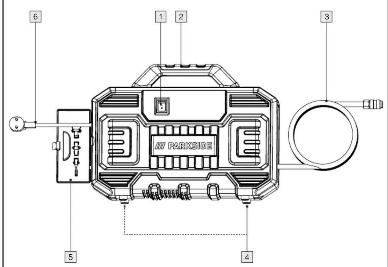
1.3 Equipment
Suitcase compressor
1 ON/OFFswitch (with integrated indicator light)
2 Transport handle
3 Compressed air hose with quick-release coupling
4 Feet
5 Accessories compartment
6 Mains connection cable
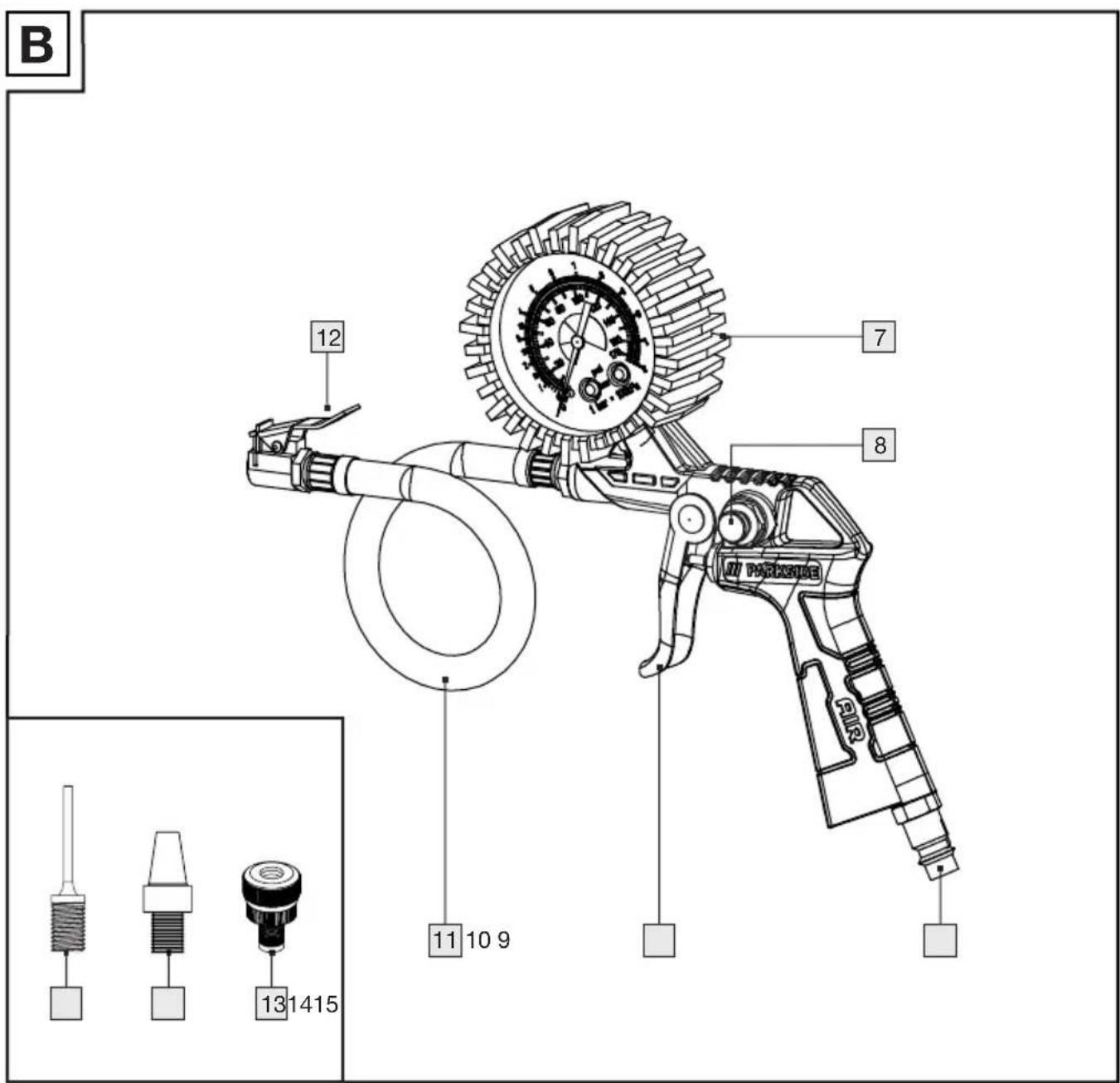
Air Tyre Inflator PDRF 10 A1
7 Pressure gauge
8 Vent valve
9 Compressed air connection
10 Trigger
11 Hose
12 Valve plug
13 Adapter for inflation valves
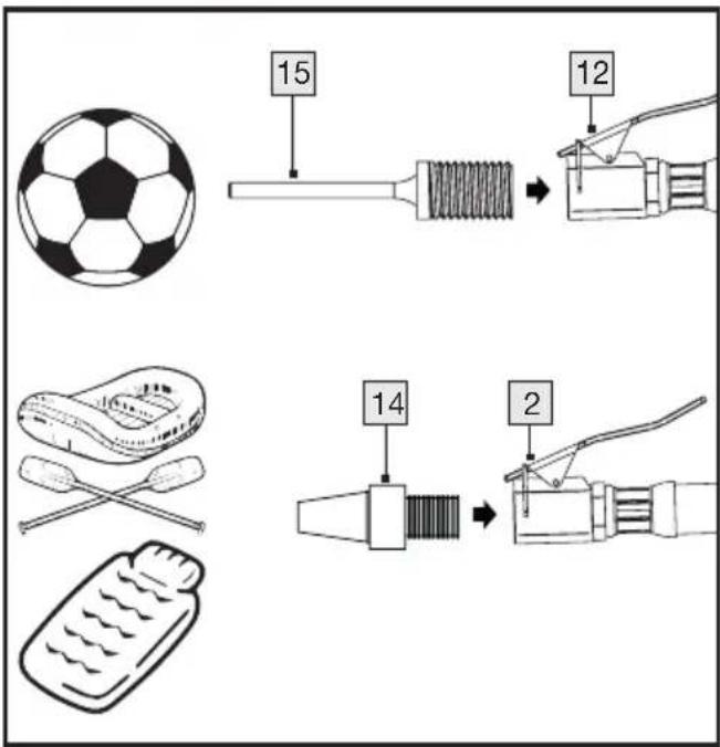
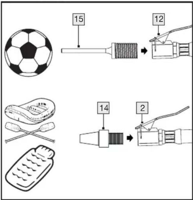
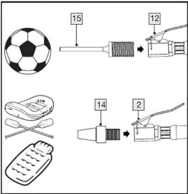
14 Universal adapter
15 Ball hollow needle
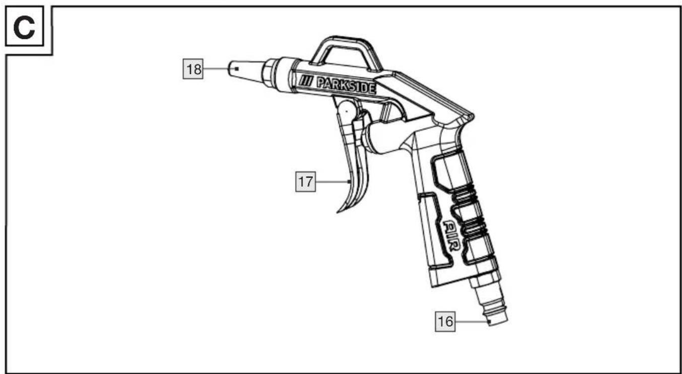
Air Blow Gun PDBP 6 A1
16 Compressed air connection
17 Trigger
18 Nozzle
1.4 Technical data
Nominal voltage: 220-240 V \~, 50 Hz (Alternating current)
Engine power: 1,1 KW
Operating mode: S3 15% 10 min.
Compressor speed: 3550 min -1
Operating pressure: max. 8 bar
Theo. Suction capacity: 180 l/min.
Degree of protection: IPX0
Protectionclass:II/
(Double insulation)
Device weight: ca. 5,8 kg
Operating mode S3-15%-10min S3 = intermittent operation without influence of the start-up process. This means that the maximum operating time during a period of 10 minutes is 15% (1.5 minutes).
Noise emission value
Measured value for noise determined in accordance with EN 62841-1 and EN 1012-1.
The A-weighted noise level at the workplace is typically:
Sound pressure level (at the operator station) L_PA = 80,2 dB (A)
Uncertainty K = 3 dB (A)
According to 2000/14/EC and 2005/88/EC:
Sound power level L_WA = 92,4 dB (A)
Uncertainty K = 1,91 dB (A)
Sound power level L_WA = 94 dB (A)

Wear hearing protection!
Explanations of all symbols found on the product
△WARNING! | WARNINGRead the operating instructions before commissioning. |
 | Operating manual must be read. |
 | Do not open the tap until the air hose is connected. |
 | Do not leave on |
 | Compressor system can start up without warning. |
 | Danger of hot temperatures |
 | Protection class II |
 | Do not expose to rain! |
 | Wear eye protection |
 | Wear breathing protection |
 | Wear hearing protection |
 | Wear protective gloves |
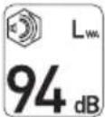 | Guaranteed sound power level |
2. Safety instructions
2.1 General safety instructions for power tools

WARNING Read all safety information, instructions, illustrations and technical data provided with this power tool. Failure to comply with the following instructions may result in electric shock, fire and/or serious injury.
KEEP ALL SAFETY INFORMATION AND INSTRUCTIONS FOR FUTURE REFERENCE.
The term ‘power tool’ used in the safety instructions refers to mains-powered power tools (with mains cable) or battery-powered power tools (without mains cable).
1) Job security
a) Keep your work area clean and well lit. Disorganisation or unlit work areas can lead to accidents.
b) Do not work with the power tool in potentially explosive atmospheres containing flammable liquids, gases or dust. Power tools generate sparks that can ignite the dust or vapours.
c) Keep children and other persons away when using the power tool. You may lose control of the power tool if you are distracted.
2) Electrical safety
a) The plug of the power tool must fit into the socket. The plug must not be modified in any way. Do not use adapter plugs together with earthed power tools. Unmodified plugs and matching sockets reduce the risk of electric shock.
b) Avoid body contact with earthed surfaces such as pipes, heaters, cookers and refrigerators. There is an increased risk of electric shock if your body is earthed.
c) Keep power tools away from rain or wet conditions. The ingress of water into a power tool increases the risk of electric shock.
d) Do not use the connecting cable for any other purpose than to carry or hang up the power tool or to pull the plug out of the socket. Keep the connecting cable away from heat, oil, sharp edges or moving parts. Damaged or entangled connecting cables increase the risk of electric shock.
e) If you are working outdoors with a power tool, only use extension cables that are also suitable for outdoor use. The use of an extension cable suitable for outdoor use reduces the risk of electric shock.
f) If operating the power tool in a damp environment is unavoidable, use a residual current circuit breaker. The use of a residual current circuit breaker reduces the risk of electric shock.
3) Safety of persons
a) Be alert, pay attention to what you are doing and use common sense when working with a power tool. Do not use a power tool if you are tired or under the influence of drugs, alcohol or medication. A moment of carelessness when using the power tool can lead to serious injury.
b) Wear personal protective equipment and always wear safety goggles. Wearing personal protective equipment, such as a dust mask, non-slip safety shoes, hard hat or hearing protection, depending on the type and use of the power tool, reduces the risk of injury.
c) Avoid unintentional start-up. Ensure that the power tool is switched off before connecting it to the power supply and/or battery, picking it up or carrying it. If you have your finger on the switch while carrying the power tool or connect the power tool to the power supply when switched on, this can lead to accidents.
d) Remove adjusting tools or spanners before switching on the power tool. A tool or spanner that is in a rotating part of the power tool can cause injury.
e) Avoid abnormal posture. Ensure that you are standing securely and keep your balance at all times. This allows you to better control the power tool in unexpected situations.
f) Wear suitable clothing. Do not wear loose clothing or jewellery. Keep hair, clothing and gloves away from moving parts. Loose clothing, jewellery or long hair can be caught by moving parts.
g) If dust extraction and collection devices can be fitted, make sure that they are connected and used correctly. Use of a dust extraction system can reduce dust hazards.
h) Do not be lulled into a false sense of security and do not ignore the safety rules for power tools, even if you are familiar with the power tool after using it many times. Careless behaviour can lead to serious injuries within fractions of a second.
4) Use and handling of the power tool
a) Do not overload the power tool. Use the power tool intended for your work. With the right power tool, you can work better and more safely in the specified power range.
b) Do not use a power tool if the switch is defective. A power tool that can no longer be switched on or off is dangerous and must be repaired.
c) Disconnect the plug from the socket and/or remove a removable battery before making device settings, changing insert tool parts or putting the power tool away. This precautionary measure prevents the power tool from starting unintentionally.
d) Keep unused power tools out of the reach of children. Do not allow persons who are not familiar with the power tool or have not read these instructions to use it. Power tools are dangerous when used by inexperienced persons.
e) Maintain power tools and tools with care. Check whether moving parts are working properly and are not jammed, whether parts are broken or damaged in such a way that the function of the power tool is impaired. Have damaged parts repaired before using the power tool. Many accidents are caused by poorly maintained power tools.
f) Keep cutting tools sharp and clean. Carefully maintained cutting tools with sharp cutting edges jam less and are easier to guide.
g) Use power tools, accessories, tools etc. in accordance with these instructions. Take into account the working conditions and the work to be carried out. The use of power tools for applications other than those for which they are intended can lead to dangerous situations.
h) Keep handles and grip surfaces dry, clean and free from oil and grease. Slippery handles and gripping surfaces do not allow safe operation and control of the power tool in unforeseen situations.
5) Service
a. Only have your power tool repaired by qualified specialists and only with original spare parts. This ensures that the safety of the power tool is maintained.
2.2 Additional safety instructions
RECOMMENDATION
Use a residual current device (RCD) with a tripping current of 30 mA or less.
If the mains connection cable of this appliance is damaged, it must be replaced with a special connection cable available from the manufacturer or its customer service centre.
- Observe the accident prevention regulations. In addition to the instructions in these operating instructions, the general safety and accident prevention regulations of the local authorities must be observed.
- The operating instructions must always be kept in the immediate vicinity of the compressor and be available to the operating personnel.
WARNING!
The compressor must not be used in potentially explosive atmospheres. Fireplaces, open lights or sparking machines must not be present or operated.
- Do not eat, drink or smoke in areas where work is being carried out.
- Use only in well ventilated areas or provide local exhaust ventilation.
There is no protection against water, i.e. the appliance must not be used in damp or wet rooms or in the rain or in rooms where there is paint and/or dust mist. Ensure that the appliance does not come into contact with water or moisture during operation or storage. Short-term outdoor use of the compressor in dry ambient conditions is permitted. DO NOT use this compressor to draw in flammable gases ex and/or paint and dust mist. - Avoid contact with hot parts. Do not touch any hot parts on the appliance. Please note that various components
can store heat and can cause burns even after the appliance has been used.
- Only move the appliance using the transport handle provided.
2.3 General safety rules for the tyre inflation gauge
- The safety instructions must be read and understood before setting up, operating, repairing and maintaining the tyre inflator and before working in the vicinity of the device. Failure to do so may result in serious physical injury.
- The tyre pressure gauge may only be set up, adjusted or used by appropriately qualified and trained operators.
This tyre pressure gauge must not be modified. Modifications can reduce the effectiveness of the safety measures and increase the risks for the operator. - The safety instructions must not be lost. Give them to the operator.
■ Never use damaged devices. - Check labels and inscriptions for completeness and legibility. The appliance must be inspected regularly to check that the machine is labelled with the clearly legible ratings and markings required in these operating instructions. The user must contact the manufacturer to obtain replacement labels if necessary.
- The operator and maintenance personnel must be physically capable of handling the size, mass and power of the machine.
■ Make sure that your body is balanced and that you have a secure hold.
In the event of an interruption in the power supply, release the trigger. - Do not blow on people or clean clothing on the body with the tyre inflator. Risk of injury!
3. Commissioning
3.1 Connecting the compressor
- Plug the mains connection cable 6 of the appliance into a socket. The appliance is now supplied with power.
- You can now switch the appliance on using the ON/OFF switch 1. The indicator light on the ON/OFF switch lights up.
3.2 Connecting the compressed air unit
■ Ensure that you only use compressed air for operation that is cleaned and free of condensation and oil.
■ Connect the compressed air hose with quick-release coupling to the compressed air connection 9/16 on the appliance.
4. Operating the compressed air blow gun
4.1 Before commissioning
The product may only be operated with cleaned, condensate-free and oil-free compressed air. The maximum working pressure of 8 bar on the product must not be exceeded. Connect the product to a suitable compressed air source by connecting the quick coupling of the supply hose to the compressed air connection 16 on the product. The locking mechanism is automatic.
4.2 Operation of the compressed air blow gun
- Point the nozzle 18 at the surface you want to spray with compressed air.
- Switch on: Press the trigger 17 to switch on the appliance.
- Switch off: Release the trigger 17 to switch off the appliance.
■ Disconnect the product from the compressed air source once work is complete.
5. Operating the compressed air tyre pressure gauge
5.1 Before commissioning
The product may only be operated with cleaned, condensate-free and oil-free compressed air. The maximum working pressure of 8 bar on the product must not be exceeded. Connect the product to a suitable compressed air source by connecting the quick coupling of the supply hose to the compressed air connection 9 on the product. The locking mechanism is automatic.
- Press the quick-release lever 2 down to attach it.
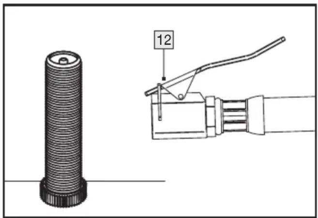
Place the quick-release lever 12 on the valve and then release it again.
■ Actuate the trigger 10. - Read the built-up air pressure on the pressure gauge 7.
■ Release the trigger 10 again. - Press the quick-release lever 12 down and pull it off the valve.
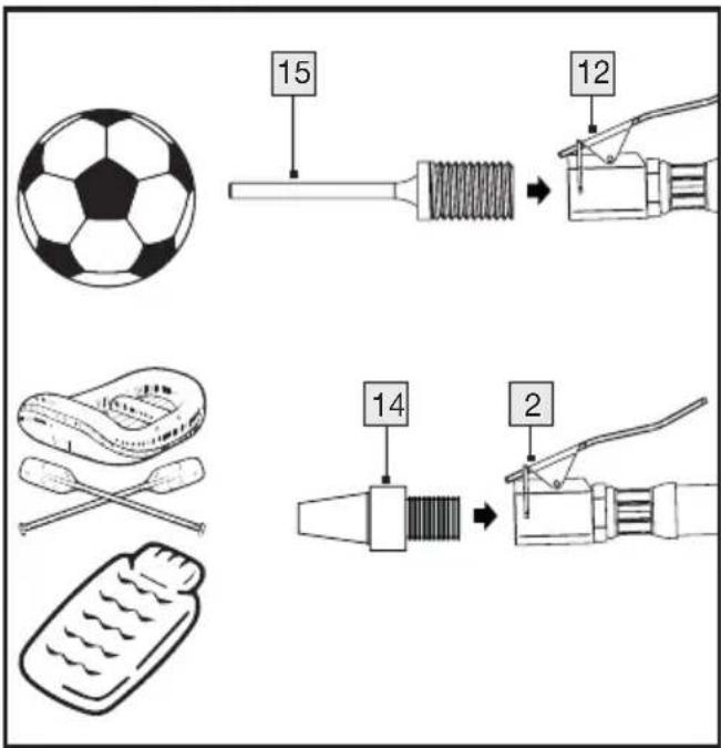
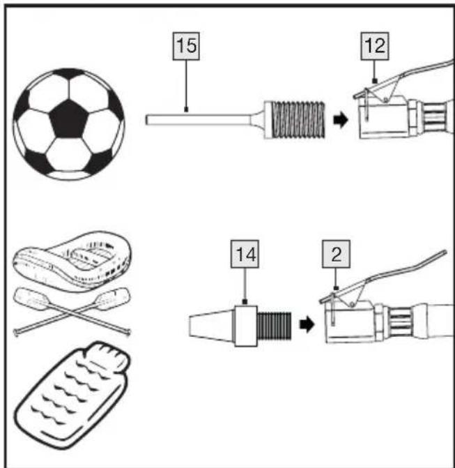
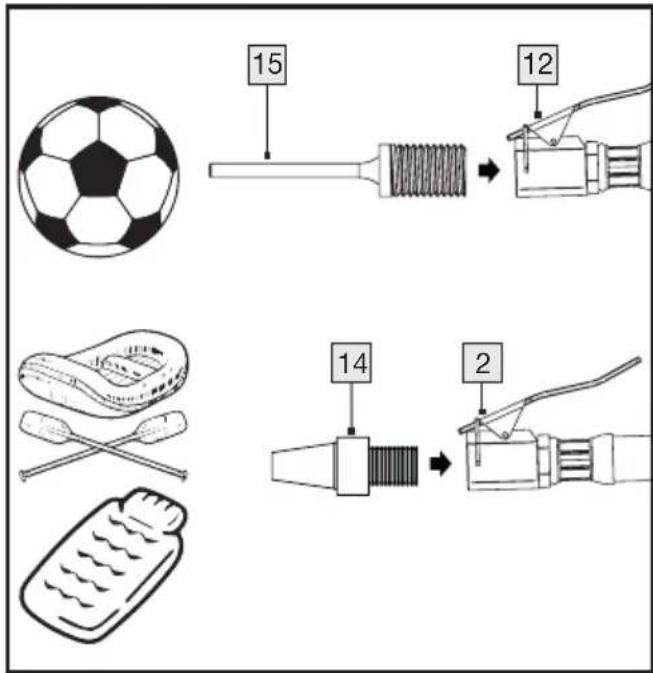
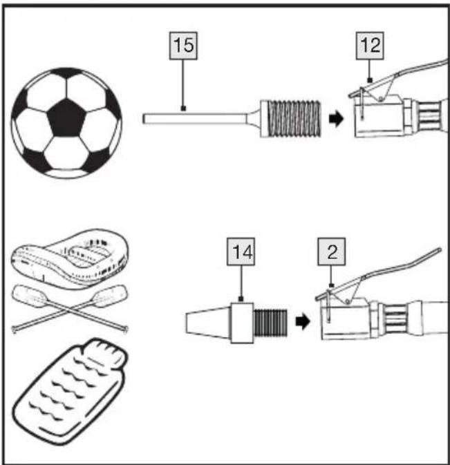
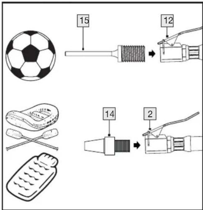
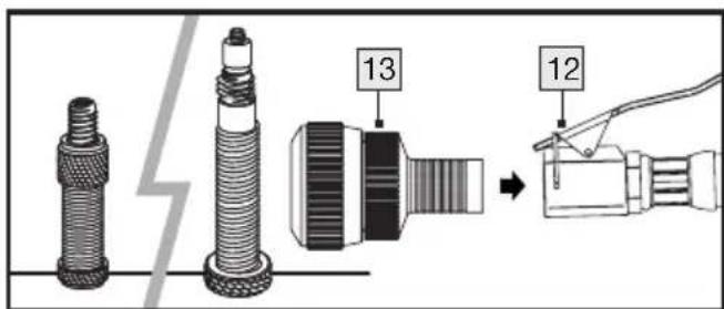
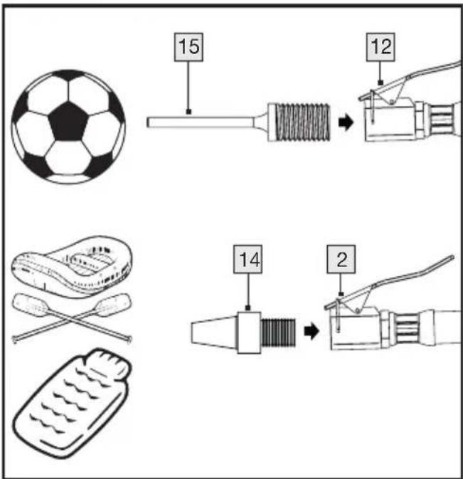
5.2 With valve adapter, ball needle, universal adapter
■ Press the quick-release lever 12 down to attach it.
- Insert the valve adapter ^14 into the quick-release lever ^12 and then release it again.
■ Now press the valve adapter 14 onto the valve.
■ Actuate the trigger 10.
Read the built-up air pressure on the pressure gauge 7.
■ Release the trigger 10 again.
- Press the quick-release lever 12 downwards and pull it off the valve.

6. Problem solution
| Malfunction Possible cause(s) Remedy | ||
| The engine does not start. No | or too low voltage. Ensure that | at the power cord6 is plugged into the pow-er outlet. Check the fuse and replace it if necessary. Check the mains voltage. |
| No or too low voltage. | Press the on/off switch1 to position ‘l’ to switch on the compressor. | |
| The extension cable is too long or too thin. | Replace the extension cable (min. 1.5 mm2, max. 5 m long). Motor starts again. | |
| The compressor runs without interruption | Connected compressed air tools and appliances consume too much air. | As this is an appliance without a boiler, constant ‘running’ is not a fault. To switch off, press the main switch. Always observe the switch-on duration of the appliance: S3/15% |
| Strong vibrations or unusual noises. | Connecting parts are loose. | Check all connecting parts and tighten them carefully if necessary. |
7. Maintenance and cleaning

WARNING! RISK OF INJURY
Before working on the device, switch it off and disconnect the mains cable.
- Clean the appliance regularly, preferably always immediately after finishing work.
- Clean the housing with a dry cloth - never use petrol, solvents or cleaning agents that attack plastic.
■ Ventilation openings must always be un-obstructed.
Do not use any sharp objects to clean the appliance. Do not allow any liquids to get inside the appliance. Otherwise the appliance may be damaged.
■ The device is maintenance-free.
■ Make sure that the appliance has cooled down completely, otherwise there is a risk of burns.
The device must be depressurised before all cleaning and maintenance work. To do this, use the vent valve 8 until no more air escapes.
NOTE: No maintenance is required for this appliance. Do not open the appliance under any circumstances. The appliance may only be repaired by an authorised service centre or customer service. If one of the faults described below occurs, please note the following:
■ Disconnect the device from any power supply.
- Allow the appliance to cool down and wait a short time to neutralise the residual energy.
■ Ensure that the appliance is in a safe condition.
Observe the labelling of the packaging materials when separating waste; these are marked with abbreviations (a) and numbers (b) with the following meaning: 1–7: Plastics/20–22: Paper and cardboard/80-98: Composites.
8. Disposal

The packaging is made from environmentally friendly materials that can be disposed of at local recycling centres.
You can find out how to dispose of your old appliance from your local authority.


These logos are only valid for Spain.


The Triman logo is valid in France only.
This product is subject to the European Directive 2012/19/EU.
Do not dispose of the product in household waste, but via municipal collection points for material recycling! Further information on how to dispose of the discarded device can be obtained from your local authority or city council.

9. ROWI Germany GmbH Warranty
Dear Customer,
This appliance has a 3-year warranty valid from the date of purchase. If this product has any faults, you, the buyer, have certain statutory rights. Your statutory rights are not restricted in any way by the warranty described below.
Warranty conditions
The validity period of the warranty starts from the date of purchase. Please keep your original receipt in a safe place. This document will be required as proof of purchase.
If any material or production fault occurs within three years of the date of purchase of the product, we will either repair or replace the product for you or refund the purchase price at our discretion. This warranty service is dependent on you presenting the defective appliance and the proof of purchase (receipt) and a short written description of the fault and its time of occurrence.
If the defect is covered by the warranty, your product will either be repaired or replaced by us. The repair or replacement of a product does not signify the beginning of a new warranty period.
Warranty period and statutory claims for defects
The warranty period is not prolonged by repairs effected under the warranty. This also applies to replaced and repaired components. Any damage and defects present
at the time of purchase must be reported immediately after unpacking. Repairs carried out after expiry of the warranty period shall be subject to a fee.
Scope of the warranty
This appliance has been manufactured in accordance with strict quality guidelines and inspected meticulously prior to delivery. The warranty covers material faults or production faults. The warranty does not extend to product parts subject to normal wear and tear or fragile parts such as switches, batteries or those made of glass.
The warranty does not apply if the product has been damaged, improperly used or improperly maintained. The directions in the operating instructions for the product regarding proper use of the product are to be strictly followed. Uses and actions that are discouraged in the operating instructions or which are warned against must be avoided.
This product is intended solely for private use and not for commercial purposes. The warranty shall be deemed void in cases of misuse or improper handling, use of force and modifications/repairs which have been carried out by one of our authorised Service centres.
Warranty claim procedure
To ensure quick processing of your case, please observe the following instructions:
- Please have the till receipt and the item number (IAN 504091_2501) available as proof of purchase.
Please refer to the type plate on the product, an engraving on the product, the title page of your manual (bottom left) or the sticker on the back or bottom of the product for the item number.
If functional errors or other defects occur, please first contact the service department listed below by telephone or email.
- You can then send a product that has been identified as defective to the service address provided, enclosing the proof of purchase (receipt) and details of the defect and when it occurred, free of postage.

You can view and download these and many other manuals at parkside-diy.com. This QR code will take you directly to parkside-diy.com. Select your country and search for the manuals using the search mask. Entering the article number (IAN) 504091_2501 will take you to the operating instructions for your article.
10. Service
notIf any problems occur during use of your ROWI Germany product, please proceed as follows:
Contact us
You can contact the service team of ROWI Germany at:
ROWI Germany GmbH
(free call from a German landline)
IAN 504091_2501
Most problems can be resolved with the skilled technical support of our Service Team.
11. Translation of the original declaration of conformity C€
We, ROWI Germany GmbH, Werner-von-Siemens-Str. 27, 76694 Forst, Germany, hereby declare that this product complies with the following standards, standardising documents and directives:
Machinery Directive: 2006/42/EG
Electromagnetic compatibility:
2014/30/EU
Outdoor guideline:
2000/14/EG + 2005/88/EG
RoHS Directive: 2011/65/EU* incl. the delegated directive (EU) 2015/863
Applied harmonised standards:
EN 62841-1:2015/A11:2022
EN 1012-1:2010
EN IEC 55014-1:2021
EN IEC 55014-2:2021
EN IEC 61000-3-2:2019/A2:2024
EN 61000-3-3:2013/A2:2021
Device designation / model number:
Portable Compressor / PMK 1100 A1
Machinery Directive: 2006/42/EG
Applied harmonised standards:
EN 1953:2013
(Air Tyre Inflator / PDRF 10 A1)
AfPS GS 2019:01 PAK
Device designation / model number:
Air Blow Gun / PDBP 6 A1
Air Tyre Inflator / PDRF 10 A1
Year of manufacture: 06/2025
Lot number: IAN 504091_2501
Documentation manager:
Marc Stockenberger
Location: Forst
Date/manufacturer's signature:
16.06.2025

Marc Stockenberger
Managing Director
We reserve the right to make technical changes in the interests of further development.
The manufacturer bears sole responsibility for issuing this declaration of conformity.
* The object of the declaration described above complies with the provisions of Directive 2011/65/EU of the European Parliament and of the Council of 8 June 2011 on the restriction of the use of certain hazardous substances in electrical and electronic equipment.
6. Problemlösung
Incertitude K = 3 dB (A)
Marc Stockenberger
Directeur général
5.2 Met ventieladapter, ballenaald, universele adapter
6. Řešení problémů

Podl'a 2000/14/ES a 2005/88/ES: