
PKO 400 A1 - Compressor PARKSIDE - Free user manual and instructions
Find the device manual for free PKO 400 A1 PARKSIDE in PDF.


| Product type | Air compressor |
| Brand | Parkside |
| Model | PKO 400 A1 |
| Power supply | 230 V ~ 50 Hz |
| Motor power | 2.2 kW |
| Max operating pressure | 8 bar |
| Tank volume | 50 L |
| Theoretical suction power | 400 L/min |
| Air flow at 7 bar | 160 L/min |
| Acoustic level (L_WA) | 94 – 97 dB |
| Protection class | IP20 |
| Weight | 44 kg |
| Recommended motor oil | SAE 15W-40 |
| Oil capacity | 0.3 L |
| Dimensions (approx.) | 70 × 40 × 60 cm |
| Tank maintenance | Drain condensation water after each use |
| Air filter maintenance | Clean every 300 hours of service |
| Oil change | First oil change at 100 h, then every 500 h |
| Safety | Safety valve, overload protection, pressure switch |
| Warranty | 3 years |
| Spare parts | Available via after-sales service (www.isc-gmbh.info) |
Frequently Asked Questions - PKO 400 A1 PARKSIDE
User questions about PKO 400 A1 PARKSIDE
0 question about this device. Answer the ones you know or ask your own.
Ask a new question about this device
Download the instructions for your Compressor in PDF format for free! Find your manual PKO 400 A1 - PARKSIDE and take your electronic device back in hand. On this page are published all the documents necessary for the use of your device. PKO 400 A1 by PARKSIDE.
USER MANUAL PKO 400 A1 PARKSIDE
Operation and Safety Notes Original operating instructions
IAN 73783
BE
Before reading, unfold the page containing the illustrations and familiarise yourself with all functions of the device.


GB Operation and Safety Notes Page 48
-2-


-3-


natural_image
Close-up of a mechanical component with labeled parts B, showing internal structure and mounting hardware (no readable text or symbols)
natural_image
Close-up of a hand operating a mechanical device with a knob and labeled part (no readable text or symbols)-4-





natural_image
Three circular mechanical components with labeled CDF indicators, shown from different angles (no text or symbols on the components themselves)
-5-

FR/BE
Sommaire
9.9 Transport (fi gure 1)
Noise measured: L_w0 = 91 dB (A); guaranteed L_w0 = 97 dB (A)
P = 2.2 KW; L/∅ = cm
Notifi ed Body: TÜV SÜD Industrie Service GmbH, 0036
2006/28/EC
Emission No.:
Standard references: EN 1012-1; EN 61000-6-1; EN 61000-6-3; EN 61000-3-2; EN 61000-3-11
Yu Feng Quing/Product-Management/Weichselgartner/General-Manager
First CE: 10
Art.-No.: 40.104.11 I.-No.: 11022
Subject to change without notice
Archive-File/Record: NAPR005122
Documents registrar: Siegfried Rolder
Wiesenweg 22, D-94405 Landau/Isar

FR/BE
13. Bon de garantie
Chère Cliente, Cher Client,
Noise measured: L_max = 91 dB (A); guaranteed L_min = 97 dB (A)
P = 2.2 KW; L/∅ = cm
Notifi ed Body: TÜV SÜD Industrie Service GmbH, 0036
2006/28/EC
Emission No.:
Standard references: EN 1012-1; EN 61000-6-1; EN 61000-6-3; EN 61000-3-2; EN 61000-3-11
Yu Feng Quing/Product-Management/Weichselgartner/General-Manager
First CE: 10
Art.-No.: 40.104.11 I.-No.: 11022
Subject to change without notice
Archive-File/Record: NAPR005122
Documents registrar: Siegfried Rolder
Wiesenweg 22, D-94405 Landau/Isar

NL/BE
13. Garantiebewijs
Geachte klant,
Noise measured: L_max = 91 dB (A); guaranteed L_min = 97 dB (A)
P = 2,2 KW; L/∅ = cm
Notifi ed Body: TÜV SÜD Industrie Service GmbH, 0036
2006/28/EC
Emission No.:
Standard references: EN 1012-1; EN 61000-6-1; EN 61000-6-3; EN 61000-3-2; EN 61000-3-11
Yu Feng Quing/Product-Management/Weichselgartner/General-Manager
First CE: 10
Art.-No.: 40.104.11 I.-No.: 11022
Subject to change without notice
Archive-File/Record: NAPR005122
Documents registrar: Siegfried Rolder
Wiesenweg 22, D-94405 Landau/Isar

DE/AT/CH
13. Garantieurkunde
- Introduction....50
- Safety regulations....50
- Layout and items supplied....52
- Proper use....53
- Technical data....53
- Before starting the equipment....53
- Assembly and starting 54
- Replacing the power cable....54
- Cleaning, maintenance, storage, ordering spare parts and transport....55
- Disposal and recycling....56
- Possible causes of failure....58
- Declaration of conformity....59
- Warranty certificate....60


The reprinting or reproduction by any other means, in whole or in part, of documentation and papers accompanying products is permitted only with the express consent of the iSC GmbH.
Subject to technical changes
-48-

GB

Caution - Read the operating instructions to reduce the risk of inquiry

Wearear-muffs. The impact of noise can cause damage to hearing.

Beware of electrical voltage!

Beware of hot parts!


Warning! The equipment is remote-controlled and may start-up without warning.

Caution! Before using for the first time, check the oil level and replace the oil sealing plug!

Important! Do not open the stopcock/pressure regulator until the air hose is connected.

OFF
ON
If the equipment is overloaded, the overload switch will shut down in order to prevent damage. Once the equipment has cooled down, activate the button to start up again.
-49-

GB
1. Introduction
Congratulations on your new purchase. You have decided in favor of a high-quality product. The operating instructions are a part of this product. They contain information of importance for your safety, for the use of the product and for its disposal. Before you use the product, acquaint yourself with all the information concerning its operation and safety. Use the product only as described and only for the listed areas of application. If you hand on the product to other people, give them all the documentation as well.
2. Safety regulations
Caution!
Read all safety regulations and instructions.
Any errors made in following the safety regulations and instructions may result in an electric shock, fire and/or serious injury.
Keep all safety regulations and instructions in a safe place for future use.
2.1 Safety information
⚠️ Important! The following basic safety actions must be taken when using this compressor in order to protect the user from electric shocks and the risk of injury and fire. Read and follow these instructions before using the equipment.
- Keep your work area tidy Untidy work areas can result in accidents.
- Check the ambient conditions Do not expose the compressor to rain. Never use the compressor in damp or wet locations. There is a risk of electric shock! Provide good lighting. Do not use the compressor near flammable liquids or gases. There is a risk of explosion!
- Protect yourself against electric shocks
Avoid bodily contact with earthed parts, e.g. pipes, radiators, cookers and refrigerators.
- Keep children away!
Do not allow other persons to touch the compressor or cable, keep them away from your work area. - Keep your compressor in a safe place When unused, the compressor must be stored in a dry, locked room out of children's reach.
- Do not overload your compressor
It will run better and safer within its quoted capacity range.
• Wear suitable work clothes
Never wear loose fitting clothes or jewellery. They may get caught in moving parts. Rubber gloves and non-slip shoes are recommended when working outdoors. Wear a hair net if you have long hair. Risk of injury! - Do not use the cable for purposes other than that for which it is designed
Do not carry the compressor by its cable and do not use the cable to pull the plug out of the socket. Protect the cable from heat, oil and sharp edges. The cable/plug could become damaged.
Take care of your compressor Keep your compressor clean in order to work well and safely. Follow the maintenance instructions. Check the power plug and cable on a regular basis and have them replaced by an authorized specialist if they are damaged. Check the extension cable regularly and replace it if damaged. - Pull out the power plug When not in use and before carrying out any maintenance work.
- Avoid unintentional starting Make sure that the switch is turned off when connecting to the power supply.
- When using an extension cable outdoors
Check that it is approved for outdoor duty and is marked accordingly. - Be alert at all times Watch what you are doing. Use common sense when working. Never use the compressor when you are distracted.
- Check your compressor for damage Before using the compressor again, carefully check the safety devices and any slightly da-
GB
maged parts to ensure that they are in good working order. Check that the moving parts are working correctly, that they do not jam, and that no parts are damaged. Make sure that all parts are fitted correctly to ensure that the equipment remains safe to use. Unless otherwise stated in the operating instructions, damaged guards and parts have to be repaired or replaced by a customer service workshop. Damaged switches have to be replaced by a customer service workshop. Never use an electric power tool with a switch that cannot be turned on and off.
- Important!
For your own safety you must only use the accessories and additional units listed in the operating instructions or recommended or specified by the manufacturer. The use of mounted tools or accessories other than those recommended in the operating instructions or catalog may place your personal safety at risk.
- Leave all repairs to a qualified electrician
Repairs must be left strictly to qualified electricians or the user might suffer an accident.
Noise
Wear ear muffs when you use the compressor.
• Replacing the power cable
To prevent hazards, leave the replacement of damaged power cables strictly to the manufacturer or a qualified electrician. There is a risk of electric shock!
• Inflatingtires
Directly after inflating tires, check the pressure with a suitable pressure gauge, for example at your filling station.
• Roadworthy compressors for building site operations
Make sure that all lines and fittings are suitable for the maximum permissible operating pressure of the compressor.
• Place of installation
Set up the compressor on an even surface.
• Make sure that all compressed air lines and fittings are suitable for the maximum permissible operating pressure of the compressor.
• For pressures above 7 bar it is recommended
to use an air line with a safety cable.
2.2 Safety instructions for working with compressed air and blasting guns
- The compressor pump and lines can become very hot during operation. Touching these parts will burn you.
- The air which is sucked in by the compressor must be kept free of impurities that could cause fires or explosions in the compressor pump.
- When releasing the hose coupling, hold the hose coupling piece with your hand. This way, you can protect yourself against injury from the rebounding hose.
- Wear safety goggles when working with the blow-out pistol. Foreign bodies or blown off parts can easily cause injuries.
- Do not blow at people with the blow-out pistol and do not clean clothes while being worn. Risk of injury!
2.3. Safety information for paint spraying
- Do not process any paints or solvents with a flash point below 75^ . There is a risk of explosion!
- Do not heat up paints or solvents. There is a risk of explosion!
- If hazardous liquids are processed, wear protective filter units (face guards). Also, adhere to the safety information provided by the manufacturers of such liquids.
- The details and designations of the Ordinance on Hazardous Substances, which are displayed on the outer packaging of the processed material, must be observed. Additional protective measures are to be undertaken if necessary, particularly the wearing of suitable clothing and masks.
- Do not smoke during the spraying process and/or in the work area. There is a risk of explosion! Paint vapors are easily combustible.
- Never set up or operate the equipment in the vicinity of a fire place, open lights or sparking machines.
- Do not store or eat food and drink in the work area. Paint vapors are harmful to your health.
GB
- The work area must exceed 30 m ^2 and sufficient ventilation must be ensured during spraying and drying. Do not spray against the wind. Always adhere to the regulations of the local police authority when spraying combustible or hazardous materials.
- Do not process media such as white spirit, butyl alcohol and methylene chloride with the PVC pressure hose. These media will destroy the pressure hose.
2.4 Operating pressure vessels
- You must keep your pressure vessel in good working order, operate the vessel correctly, monitor the vessel, carry out necessary maintenance and repair work immediately and meet the relevant safety precautions.
- The supervisory authority may enforce essential control measures in individual cases.
- A pressure vessel is not allowed to be used if it has faults or deficiencies that can endanger workers or third parties.
- Check the pressure vessel for signs of rust and damage each time before using. Do not use the compressor with a damaged or rusty pressure vessel. If you discover any damage, then please contact the customer service workshop.
Do not lose these safety instructions
3. Layout and items supplied
3.1 Layout
- Transporthandle
- Pressure switch
- Pressure regulator
- Quick-lock coupling (regulated compressed air)
- Pressure gauge (for reading the preset pressure)
- Non-return valve with discharge line
- Pressure vessel
- Supporting foot
- Drain plug for condensed water
- Axle screw
-
Wheel
-
Handle
- Compressor pump
-
Pressure gauge (for reading the vessel pressure)
-
Air fi Iter
- Oil sealing plug
- ON/OFF switch
- Oil drainage screw with oil level window
- Safety valve
- Quick-lock coupling (unregulated compressed air)
- Oil filler opening
- Washer
- Spring washer
- Nut
- Screw
- Washer
- Washer
- Nut
3.2 Items supplied
- Open the packaging and take out the equipment with care.
- Remove the packaging material and any packaging and/or transportation braces (if available).
• Check to see if all items are supplied. - Inspect the equipment and accessories for transport damage.
• If possible, please keep the packaging until the end of the guarantee period.
Important!
The equipment and packaging material are not toys. Do not let children play with plastic bags, foils or small parts. There is a danger of swallowing or suffocating!
-52-

GB
4. Proper use
The compressor is designed to generate compressed air for compressed-air driven tools which can be driven with an air volume of up to approx. 400 l/min (e.g. a tire inflator, blow-out pistol and paint spray gun). Compressed air tools with very high air consumption have only limited suitability for use with this compressor. For tools with high air consumption (e.g. orbital sanders/grinders, rod grinders, hammer screwdrivers), check whether the compressor's air output is sufficient to operate the tool in question. The volume of air supplied by the compressor must be greater than the volume of air consumed by the compressed air tool at its operating pressure.
The equipment is to be used only for its prescribed purpose. Any other use is deemed to be a case of misuse. The user / operator and not the manufacturer will be liable for any damage or injuries of any kind caused as a result of this.
Please note that our equipment has not been designed for use in commercial, trade or industrial applications. Our warranty will be voided if the machine is used in commercial, trade or industrial businesses or for equivalent purposes.
5.Technical data
Mains connection: 230 V \~ 50 Hz
Motor rating kW: 2.2 kW
Operating mode: S1
Compressor speed min ^-1 : 2850
Operating pressure bar: ....max. 8
Pressure vessel capacity (in liters): 50
Theoretical intake capacity (l/min): .approx. 400
Effective delivery rate at 7 bar: approx. 160l/min
Sound power level L_WA in dB: .....97
K_WA uncertainty: 4 dB
Protection type: IP20
Weight of the unit in kg: 44
Oil (15W 40): 0.3 l
- The product meets the requirements of EN 61000-3-11 and is subject to special connection conditions. This means that use of the product at any freely selectable connection point is not allowed.
- Given unfavorable conditions in the power supply the product can cause the voltage to fluctuate temporarily.
- The product is exclusively intended for use at connection points that have a continuous current-carrying capacity of at least 100 A per phase.
- As the user, you are required to ensure, in consultation with your electric power company if necessary, that the connection point at which you wish to operate the product meets the specified requirements.
6. Before starting the equipment
Before you connect the equipment to the mains supply make sure that the data on the rating plate are identical to the mains data.
- Check the equipment for damage which may have occurred in transit. Report any damage immediately to the transport company which was used to deliver the compressor.
• Install the compressor near the point of consumption. - Avoid long air lines and supply lines (extension cables).
• Make sure that the intake air is dry and dust-free. - Do not install the compressor in a damp or wet room.
- The compressor may only be used in suitable rooms (with good ventilation and an ambient temperature from +5 °C to 40 °C). There must be no dust, acids, vapors, explosive gases or inflammable gases in the room.
- The compressor is designed to be used in dry rooms. It is prohibited to use the compressor in areas where work is conducted with sprayed water.
• The oil level in the compressor pump has to
-53-
GB
be checked before putting the equipment into operation (see 9.4).
7. Assembly and starting
⚠️ Important!
You must fully assemble the appliance before using it for the first time!
You will require the following tools for assembly and installation:
- 1 x open-ended wrench size 14 mm (not included)
- 2 x open-ended wrench size 17 mm (not included)
- 1 x open-ended wrench size 23 mm (not included)
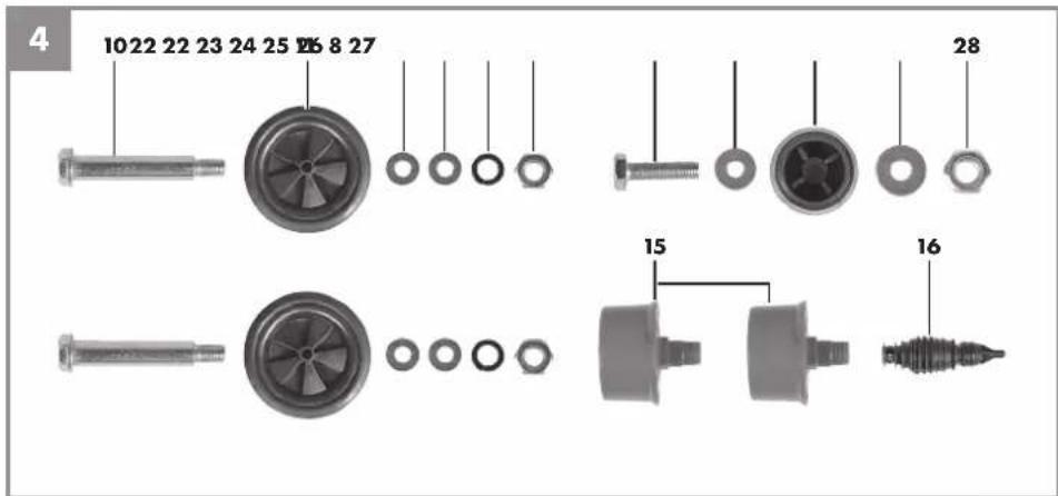
7.1 Fitting the wheels (11)
Fit the supplied wheels as shown in Figure 5.
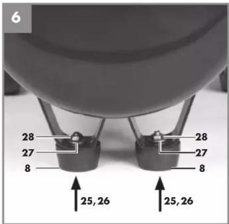
7.2 Fitting the supporting feet (8)
Fit the supplied supporting feet as shown in Figure 6.
7.3 Fitting the air filters (15)
Remove the transportation stopper (B) and screw the air fil ters (15) securely to the equipment (Fig. 7, 8). Make sure that the intake opening on the air fil iter faces down.
7.4 Changing the transportation cover (A)
Remove the transportation cover from the oil filler opening (21) and insert the supplied oil sealing plug (16) into the oil filler opening. (Fig. 9, 10.)
7.5 Mains connection
- The compressor is equipped with a mains cable with shock-proof plug. This can be connected to any 230V \~ 50 Hz shock-proof socket which is protected by a 16 A fuse.
- Before you use the machine, make sure that the mains voltage is the same as the operating voltage (see the rating plate).
- Long supply cables, extensions, cable reels etc. cause a drop in voltage and can impede motor start-up.
- At low temperatures below +5°C, sluggishness may make starting difficult or impossible.
7.6 ON/OFF switch (Fig. 2)
Pull the ON/OFF switch (17) upwards to switch on the compressor. To switch off the compressor, press the ON/OFF switch down.
7.7 Setting the pressure (Fig. 1-3)
• Use the pressure regulator (3) to set the pressure on the pressure gauge (5).
• Pull the knob of the pressure regulator (3) in order to release the pressure regulator.
- Turn the pressure regulator knob to adjust the pressure. When the required pressure setting is reached, press the pressure regulator knob.
- The set pressure can be drawn from the quick-lock coupling (4).
- The vessel pressure can be read off the pressure gauge (14).
- The vessel pressure is drawn from the quick-lock coupling (20).
7.8 Setting the pressure switch (Fig. 1)
The pressure switch (2) is set at the factory. Cut-in pressure approx. 6 bar Cut-out pressure approx. 8 bar
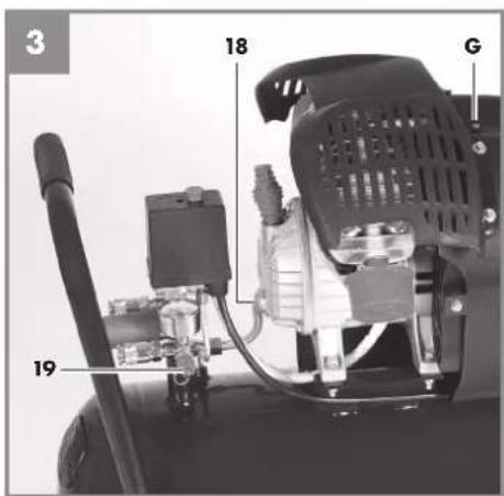
7.9 Overload cut-out (Fig. 3)
The motor of this equipment is protected against overload by an overload switch (G). If the rated current is exceeded, the overload switch (G) will shut down the equipment. After a short cooling down period, the equipment can be switched on again by pressing the overload switch (G).
8. Replacing the power cable
If the power cable for this equipment is damaged, it must be replaced by the manufacturer or its after-sales service or similarly trained personnel to avoid danger.
GB
9. Cleaning, maintenance, storage, ordering spare parts and transport
⚠️ Important!
Pull out the power plug before doing any cleaning and maintenance work on the equipment. Risk of injury from electric shock!
⚠️ Important!
Wait until the equipment has cooled down completely! Risk of burns!
⚠️ Important!
Always depressurize the equipment before carrying out any cleaning and maintenance work (see 9.7.1)! Risk of injury!
9.1 Cleaning
- Keep the equipment free of dirt and dust as far as possible. Wipe the equipment with a clean cloth or blow it down with compressed air at low pressure.
• We recommend that you clean the equipment immediately after you use it. - Clean the equipment regularly with a damp cloth and some soft soap. Do not use cleaning agents or solvents; these may be aggressive to the plastic parts in the equipment. Ensure that no water can get into the interior of the equipment.
- You must disconnect the hose and any spraying tools from the compressor before cleaning. Do not clean the compressor with water, solvents or the like.
9.2 Maintenance work on the pressure vessel (Figure 1)
Important! To ensure a long service life of the pressure vessel (7), drain off the condensed water by opening the drain valve (9) each time after using. Release the vessel pressure first (see 9.7.1). Open the drain screw by turning counter-clockwise (looking at the screw from the bottom of the compressor) so that all the condensed water can run out of the pressure vessel. Then close the drain
screw again (turn it clockwise). Check the pressure vessel for signs of rust and damage each time before using. Do not use the compressor with a damaged or rusty pressure vessel. If you discover any damage, then please contact the customer service workshop.
⚠️ Important!
The condensed water from the pressure vessel will contain residual oil. Dispose of the condensed water in an environmentally compatible manner at a suitable collection point.
9.3 Safety valve (Figure 3)
The safety valve (19) has been set for the highest permitted pressure of the pressure vessel. It is prohibited to adjust the safety valve or remove its seal. Actuate the safety valve from time to time to ensure that it works when required. Pull the ring with sufficient force until you can hear the compressed air being released. Then release the ring again.
9.4 Checking the oil level at regular intervals (Figure 11)
Place the compressor on a level and straight surface. The oil level must be between the MAX and MIN marks on the oil level window (Fig. 18). Oil change: we recommend SAE 15W 40 or equivalent. The original oil fi lling must be changed after 100 hours in operation; thereafter the oil must be drained and replaced with new oil after every 500 hours in operation.
9.5 Changing the oil (Figure 1, 10, 11)
Switch off the motor and pull the mains plug out of the socket. After releasing any air pressure (see 9.7.1) you can unscrew the oil drain screw (18) from the compressor pump (13). To prevent the oil from running out in an uncontrolled manner, hold a small metal chute under the opening and collect the oil in a container. If the oil does not drain out completely, we recommend tilting the compressor slightly. When the oil has drained out, refi t the oil drain screw (18).
GB
Dispose of the old oil at a drop-off point for old oil.
To fill in the correct quantity of oil, make sure that the compressor stands on an even surface. Fill new oil through the oil filler opening (21) until it comes up to the maximum level. This is marked with a red dot on the oil level window (18) (Figure 11). Do not exceed the maximum filling quantity. Overfilling the equipment may result in damage. Reinsert the oil sealing plug (16) into the oil filler opening (21).
9.6 Cleaning the intake filter (Fig. 2, 3, 12)
The intake fi liters (15) prevent the drawing in of dust and dirt. It is essential to clean these fi liters after at least every 300 hours in operation. A clogged intake fi liter will decrease the compressor's performance dramatically. Remove the intake fi liters from the equipment by unscrewing them. The fi liter housing (D) is plugged on the fi liter cover (C) and can be removed by applying slight pressure to the fi liter cover. Carefully tap out the air fi liters (F), the fi liter cover and the fi liter housing. Then blow out these parts with compressed air (approx. 3 bar) and reinstall in reverse order. The fi liter cover and the fi liter housing have different latching positions. When you assemble the intake fi liter, make sure that the intake opening faces down.
9.7 Storage
⚠️ Important!
Pull out the mains plug and ventilate the equipment and all connected pneumatic tools (see 9.7.1). Switch off the compressor and make sure that it is secured in such a way that it cannot be started up again by any unauthorized person.
⚠️ Important!
Store the compressor only in a dry location which is not accessible to unauthorized persons. Always store upright, never tilted! Oil may leak out!
9.7.1 Releasing excess pressure
Release the excess pressure by switching off the compressor and using the compressed air which is still left in the pressure vessel, e.g. with a compressed air tool running in idle mode or with a blow-out pistol.
9.8 Ordering replacement parts:
Please quote the following data when ordering replacement parts:
• Type of machine
• Article number of the machine
• Identification number of the machine
For our latest prices and information please go to www.isc-gmbh.info
9.9 Transport (Figure 1)
- Switch off the equipment and pull out the power plug before lifting and moving the compressor.
• Use the transport handle (1) to move the compressor. - Use the transport handle (1) and the grip (12) on the pressure vessel (7) to lift the compressor. Note the equipment's weight!
- Transport the compressor only in an upright position and secure it against tilting so that no oil runs out.
- Secure the compressor in accordance with the regulations in force for transporting equipment in motor vehicles.
10. Disposal and recycling
The unit is supplied in packaging to prevent its being damaged in transit. This packaging is raw material and can therefore be reused or can be returned to the raw material system.
The unit and its accessories are made of various types of material, such as metal and plastic. Defective components must be disposed of as special waste. Ask your dealer or your local council.
GB

For EU countries only
Never place any electric power tools in your household refuse.
To comply with European Directive 2002/96/EC concerning old electric and electronic equipment and its implementation in national laws, old electric power tools have to be separated from other waste and disposed of in an environment-friendly fashion, e.g. by taking to a recycling depot.
Recycling alternative to the return request:
As an alternative to returning the equipment to the manufacturer, the owner of the electrical equipment must make sure that the equipment is properly disposed of if he no longer wants to keep the equipment. The old equipment can be returned to a suitable collection point that will dispose of the equipment in accordance with the national recycling and waste disposal regulations. This does not apply to any accessories or aids without electrical components supplied with the old equipment.


-57-

11. Possible causes of failure
| ProblemCauseSolution | ||
| Thecompressor does not start. | 1. No supply voltage.2. Insuffi cient supply voltage.3. Outside temperature is too low.4. Motor is overheated. | 1. Check the supply voltage, the power plug and the socket-outlet.2. Make sure that the extension cable is not too long. Use an extension cable with large enough wires.3. Never operate with an outside temperature of below +5°C.4. Allow the motor to cool down. If necessary, remedy the cause of the overheating. |
| Thecompressor starts but there is no pressure. | 1. The non-return valve leaks.2. The seals are damaged.3. The drain plug for condensation water (9) leaks. | 1. Have a service center replace the non-return valve.2. Check the seals and have any damaged seals replaced by a service center.3. Tighten the screw by hand. Check the seal on the screw and replace if necessary. |
| Thecompressor starts, pressure is shown on the pressure gauge, but the tools do not start. | 1. The hose connections have a leak.2. A quick-lock coupling (4, 20) has a leak.3. Insuffi cient pressure set on the pressure regulator (3). | 1. Check the compressed air hose and tools and replace if necessary.2. Check the quick-lock coupling and replace if necessary.3. Increase the set pressure with the pressure regulator. |

-58-

12. Declaration of conformity
Noise measured: L_w0 = 91 dB (A); guaranteed L_w0 = 97 dB (A)
P = 2.2 KW; L/∅ = cm
Notifi ed Body: TÜV SÜD Industrie Service GmbH, 0036
2006/28/EC
Emission No.:
Standard references: EN 1012-1; EN 61000-6-1; EN 61000-6-3; EN 61000-3-2; EN 61000-3-11
Yu Feng Quing/Product-Management/Weichselgartner/General-Manager
First CE: 10
Art.-No.: 40.104.11 I.-No.: 11022
Subject to change without notice
Archive-File/Record: NAPR005122
Documents registrar: Siegfried Rolder
Wiesenweg 22, D-94405 Landau/Isar

GB
13.Warranty certifi cate
Dear Customer,
All of our products undergo strict quality checks to ensure that they reach you in perfect condition. In the unlikely event that your device develops a fault, please contact our service department at the address shown on this guarantee card. Of course, if you would prefer to call us then we are also happy to offer our assistance under the service number printed below. Please note the following terms under which guarantee claims can be made:
- These guarantee terms cover additional guarantee rights and do not affect your statutory warranty rights. We do not charge you for this guarantee.
- Our guarantee only covers problems caused by material or manufacturing defects, and it is restricted to the rectification of these defects or replacement of the device. Please note that our devices have not been designed for use in commercial, trade or industrial applications. Consequently, the guarantee is invalidated if the equipment is used in commercial, trade or industrial applications or for other equivalent activities. The following are also excluded from our guarantee: compensation for transport damage, damage caused by failure to comply with the installation/assembly instructions or damage caused by unprofessional installation, failure to comply with the operating instructions (e.g. connection to the wrong mains voltage or current type), misuse or inappropriate use (such as overloading of the device or use of non-approved tools or accessories), failure to comply with the maintenance and safety regulations, ingress of foreign bodies into the device (e.g. sand, stones or dust), effects of force or external influences (e.g. damage caused by the device being dropped) and normal wear resulting from proper operation of the device. This applies in particular to rechargeable batteries for which we nevertheless issue a guarantee period of 12 months. The guarantee is rendered null and void if any attempt is made to tamper with the device.
- The guarantee is valid for a period of 3 years starting from the purchase date of the device. Guarantee claims should be submitted before the end of the guarantee period within two weeks of the defect being noticed. No guarantee claims will be accepted after the end of the guarantee period. The original guarantee period remains applicable to the device even if repairs are carried out or parts are replaced. In such cases, the work performed or parts fitted will not result in an extension of the guarantee period, and no new guarantee will become active for the work performed or parts fitted. This also applies when an on-site service is used.
- In order to assert your guarantee claim, please send your defective device postage-free to the address shown below. Please enclose either the original or a copy of your sales receipt or another dated proof of purchase. Please keep your sales receipt in a safe place, as it is your proof of purchase. It would help us if you could describe the nature of the problem in as much detail as possible. If the defect is covered by our guarantee then your device will either be repaired immediately and returned to you, or we will send you a new device.
Of course, we are also happy offer a chargeable repair service for any defects which are not covered by the scope of this guarantee or for units which are no longer covered. To take advantage of this service, please send the device to our service address.
IAN 73783
-60-

natural_image
Two horizontal bar designs with grayscale shades and a central crosshair symbol (no text or labels)


-61-
natural_image
Color palette bar with grayscale shades and a small crosshair symbol (no text or labels)

CE
IAN: 73783 PKO 400 A1
Einhell Germany AG
Wiesenweg 22
D-94405 Landau/Isar
Version des Informations · Stand van de Informatie


- FR/BE
- Sommaire
- Transport (fi gure 1)
- Bon de garantie
- NL/BE
- Garantiebewijs
- 2006/28/EC
- DE/AT/CH
- Garantieurkunde
- GB
- Introduction
- Safety regulations
- Caution!
- Read all safety regulations and instructions.
- Keep all safety regulations and instructions in a safe place for future use.
- Safety information
- ⚠️ Important! The following basic safety actions must be taken when using this compressor in order to protect the user from electric shocks and the risk of injury and fire. Read and follow these instructions before using the equipment.
- - Important!
- - Leave all repairs to a qualified electrician
- Noise
- • Replacing the power cable
- • Inflatingtires
- • Roadworthy compressors for building site operations
- • Place of installation
- Safety instructions for working with compressed air and blasting guns
- Safety information for paint spraying
- Operating pressure vessels
- Do not lose these safety instructions
- Layout and items supplied
- Layout
- Items supplied
- Important!
- Proper use
- 5.Technical data
- Before starting the equipment
- Assembly and starting
- ⚠️ Important!
- You must fully assemble the appliance before using it for the first time!
- Fitting the wheels (11)
- Fitting the supporting feet (8)
- Fitting the air filters (15)
- Changing the transportation cover (A)
- Mains connection
- ON/OFF switch (Fig. 2)
- Setting the pressure (Fig. 1-3)
- Setting the pressure switch (Fig. 1)
- Overload cut-out (Fig. 3)
- Replacing the power cable
- Cleaning, maintenance, storage, ordering spare parts and transport
- Cleaning
- Maintenance work on the pressure vessel (Figure 1)
- Safety valve (Figure 3)
- Checking the oil level at regular intervals (Figure 11)
- Changing the oil (Figure 1, 10, 11)
- Dispose of the old oil at a drop-off point for old oil.
- Cleaning the intake filter (Fig. 2, 3, 12)
- Storage
- Releasing excess pressure
- Ordering replacement parts:
- Transport (Figure 1)
- Disposal and recycling
- Possible causes of failure
- Declaration of conformity
- 13.Warranty certifi cate
- CE
Brand : PARKSIDE
Model : PKO 400 A1
Category : Compressor