
POWAIR0805 - Pneumatic tool PowerPlus - Free user manual and instructions
Find the device manual for free POWAIR0805 PowerPlus in PDF.

User questions about POWAIR0805 PowerPlus
0 question about this device. Answer the ones you know or ask your own.
Ask a new question about this device
Download the instructions for your Pneumatic tool in PDF format for free! Find your manual POWAIR0805 - PowerPlus and take your electronic device back in hand. On this page are published all the documents necessary for the use of your device. POWAIR0805 by PowerPlus.
USER MANUAL POWAIR0805 PowerPlus
natural_image
Product photo of a power amplifier tool with cutouts of multiple saw blades and pads (no text or symbols visible)POWAIR0805
Fig. A
flowchart
graph LR
    1["1"] --> 2["2"]
    2 --> 3["3"]
    3 --> 4["4"]
    4 --> 5["5"]
    5 --> 6["6"]
    6 --> 7["7"]
    7 --> 8["8"]
    8 --> 9["9"]
    9 --> 10["10"]
    10 --> 11["11"]
Fig. 1

natural_image
Close-up of a hand holding a white square electronic device with a circular dot pattern on its surface (no text or symbols visible)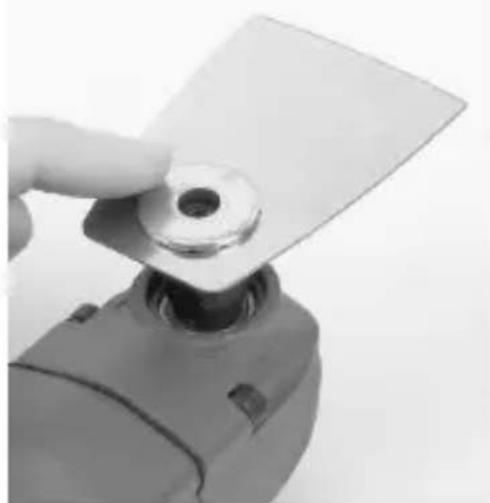
natural_image
Close-up of a hand holding a white plastic sheet with a circular hole, next to a mechanical component (no text or symbols visible)2
natural_image
Close-up of a mechanical component with a metallic plate and central hub (no visible text or symbols)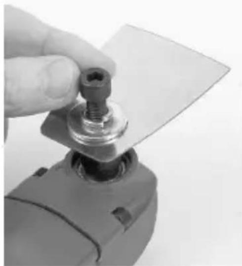
natural_image
Close-up of a hand holding a small mechanical component with a metallic base (no visible text or symbols)4

natural_image
Close-up of a hand using a power tool to lift a flat plate (no text or symbols visible)Fig 2
POWAIR0805 NL
1 TOEPASSING....2
2 BESCHRIJVING (FIG. A) 2
3 INHOUD VAN DE VERPAKKING....2
4 VEILIGHEIDSREGELS....3
13 PROBLEEMOPLOSSING....9
14 MILIEU....11
15 CONFORMITEITSVERKLARING....11
PNEUMATISCH MULTIGEREEDSCHAP POWAIR0805
1 TOEPASSING
2 BESCHRIJVING (FIG. A)
13 PROBLEEMOPLOSSING
2 DESCRIPTION (FIG. A)....2
3 LISTE DES PIECES CONTENUES DANS L'EMBALLAGE ....2
4 CONSIGNES DE SÉCURITÉ....3
| Tool runs at normal speed but loses under |
POSSIBLE CAUSES
| Motor parts worn. |
REMEDIES
| Lubricating clutch housing. |
| Check for excess clutch oil. Clutch cases need only be half full. Overfilling |
| PROBLEMS | POSSIBLE CAUSES | REMEDIES |
| load | Cam clutch worn or sticking due to lack of lubricant. | can cause drag on high speed clutch parts, i.e. a typical oiled/lubricated wrench requires 1/2 ounce of oil. GREASELUBRICATED:NOTE: Heat usually indicates insufficient grease in chamber. Severe operating conditions may require more frequent lubrication. GREASELUBRICATED:NOTE: Heat usually indicates insufficient grease in chamber. Severe operating conditions may require more frequent lubrication. |
| Tool runs slowly. Air flows slightly from exhaust | Motor parts jammed with dirt particles | Check air inlet filter for blockage.Pour air tool lubricating oil into air inlet as per instructions.Operate tool in short bursts quickly reversing rotation back and forth where applicable.Repeat above as needed. |
| Power regulator in closed position | ||
| Air flow blocked by dirt. | ||
| Tools will not run. Air flows freely from exhaust | One or more motor vanes stuck due to material build up. | Pour air tool lubricating tool into air inlet. Operate tool in short bursts of forward and/or reverse rotation where applicable.Tap motor housing gently with plastic mallet.Disconnect supply. Free motor by rotating drive shank manually where applicable |
| Tool will not shut off | ‘O’ rings throttle valve dislodged from seat inlet valve. | Replace ‘O’ ring. |

Note: Repairs should be carried out by a qualified person.
14 ENVIRONNEMENT
2 DESCRIPTION (FIG. A)....2
3 PACKAGE CONTENT LIST 2
4 SAFETY WARNINGS....3
4.1 Risks due to projected parts....4
4.2 Hazards from entanglement....4
4.3 Operating hazards....4
4.4 Hazards due to repetitive motions....4
4.5 Risks associated with accessories ....4
4.6 Please follow the following instructions:....4
4.7 Hazards in the work environment....5
5 ADDITIONAL SAFETY INSTRUCTIONS FOR PNEUMATIC MACHINERY...5
6 AIR SUPPLY....5
7 LUBRICATION 5
8 IMPORTANT!!! 6
9 LOADING AND OPERATION....6
9.1 Installing accessories (Fig. 2)....6
9.2 Switching on/off 6
9.3 Selecting the Application Tool/Accessory....7
10 MAINTENANCE....8
11 TECHNICAL DATA 8
12 NOISE....8
13 TROUBLESHOOTING....8
14 ENVIRONMENT....10
15 DECLARATION OF CONFORMITY....10
PNEUMATIC MULTI-USE TOOL
POWAIR0805
1 APPLICATION
Depending on which accessory mounted this pneumatic multi-use tool is intended for dry sanding small areas and for sawing, scraping polishing, rasping, cutting and separating.

Warning! For your own safety, read this manual and general safety instructions carefully before using the appliance. Your power tool should only be passed on together with these instructions.
2 DESCRIPTION (FIG. A)
- Trigger
- Segment saw blade with recess
- Coupler
- Segment saw blade flat
- Clamping bolt + washers
- Shovel blade
- Scraping blade
- Sanding base plate
- Plunge cut saw blade
- Sanding sheets
3 PACKAGE CONTENT LIST
- Remove all packaging materials.
- Remove remaining packing and package inserts (if included).
- Check that the package contents are complete.
- Check the appliance, the power cord, the power plug and all accessories for transportation damage.
- Keep the packing materials as long as possible till the end of the warranty period. Dispose it into your local waste disposal system afterwards.

WARNING: Packaging materials are not toys! Children must not play with plastic bags! Danger of suffocation!
1 x pneumatic multi-use tool
1x hex key
1 x Allen key
1 x Sanding plate
6 x Sanding sheets
2 x grain 60
2 x grain 80
2 x grain 240
1 x Plunge saw blade
2 x Shovel blade
2 x Segmented saw blade
1 x male Euro coupler
1 x male Orion coupler
1 x oil bottle (empty)
1 x PTFE sealing tape
1 x BMC
1 x manual

If any parts are missing or damaged, please contact your dealer.
4 SAFETY WARNINGS
Basic safety measures must be followed when using air tools to eliminate the risk of fire, electric shock and personal injury. Be sure to read and follow the notices within these operating instructions prior to using the equipment and store them in a safe location. The manufacturer assumes no liability for damages or personal injury resulting from failure to follow these operating instructions.
The hazards listed are foreseeable for general use of handheld air sanders and saws. However, the user (or their employer) must also assess specific risks which may arise from its different types of applications.
- DANGER! Keep hands and other extremities away from the sawing, cutting or sanding area of the multi-tool. Cuts may otherwise occur.
- Only use the equipment in areas of application for which it was designed!
- Never use hydrogen, oxygen, carbon dioxide or other bottled gasses to power this tool as doing so may result in an explosion and thus may cause severe injuries.
- EXPLOSION HAZARD! Never use petrol or other flammable liquids to clean the air tool! Sparks could ignite residual vapours inside the compressed air equipment resulting in the compressed air equipment exploding. Do not use the tool in explosive environments with flammable liquids, gasses or dust. Never work on materials which are or could potentially be highly flammable or explosive.
- Always wear personal protective equipment and safety glasses. Wearing personal protective equipment such as dust mask, non-slip safety shoes, hard hat or ear protectors, depending on the type of air tool and its application, reduces the risk of injuries.
■ BE CAREFUL WHEN PUTTING DOWN THE EQUIPMENT! Always put down the device so it does not rest on the trigger. This could potentially result in inadvertent activation of the tool, which in turn could result in hazards.
- DANGER! Avoid contact with live lines. This equipment is not insulated against electric shock.
- Torn or deformed sheets must not be used.
- Check whether the sanding sheets are fixed correctly.
- Ensure that no braking of the disk occurs due to lateral counter-pressure.
- Ensure that, if any sparks are produced, they are dispersed in such a way that they pose no danger.
- Check whether the maximum operational speed of the machine tool is the same or greater than the given speed of the appliance.
- Only use lubricants recommended by the manufacturer.
- Do not use the appliance if spare parts, which affect the safety of the user, are defective.
- Do not modify this equipment in any way without the manufacturer's approval.
- Disconnect the tool from the air supply after each use and when not in use.
- Discontinue use if the tool leaks or is in need of repair.
- Keep children and other persons away from the equipment during use. Distractions can cause you to lose control of the equipment.
- Put down the trigger and equipment in the event of unexpected compressor failure.
- Secure work pieces. Use clamps or a vice to secure the work piece. Holding the work piece in your hand or pressing it against your body will not allow for safe use of the equipment.
4.1 Risks due to projected parts
- If the work piece, one of the accessories or the tool itself breaks, parts may be projected at great speed.
- Always wear impact-resistant eye protection when using the machine to grind and cut. The level of required protection required should be assessed individually for each application.
- When working overhead, a safety helmet must be worn.
- In this case, the risk to other people must also be assessed.
- It must be ensured that the work piece is properly secured.
4.2 Hazards from entanglement
- Hazards from entanglement - there is the danger of suffocation, scalping or suffering cuts, when loosely fitting clothing, jewellery, hair or gloves are not kept away from the machine and its accessories.
4.3 Operating hazards
- When using the machine, the operator's hands may be at risk, for example from cutting, abrasion and heat. Wear suitable gloves to protect hands.
- The operator and maintenance personnel must be physically capable of managing the size, weight and power of the machine.
■ Torn or deformed blades must not be used! - Check that the saw blades are fixed or mounted correctly!
4.4 Hazards due to repetitive motions
- When using the grinding and cutting machine for work related tasks, the operator may experience uncomfortable sensations in hands, arms and the area of the neck and shoulder or in other parts of the body. The operator must maintain a comfortable position whilst using this tool to grind and saw, thereby ensuring a secure grip and avoiding awkward positions or positions making it difficult to maintain balance. The operator should change his posture when working for longer, to help avoid discomfort and fatigue.
- If the operator experiences symptoms such as persistently feeling unwell, discomfort, palpitations, pain, tingling, numbness, a burning sensation or stiffness, these warning signs should not be ignored. The user should (if applicable report these to the employer and) consult a qualified healthcare professional.
4.5 Risks associated with accessories
- Only use the sizes and types of accessories and consumables recommended by the manufacturer of the grinding and cutting machine.
- Please avoid direct contact with the machine tool during and after use, as it could have heated up or have sharp edges.
4.6 Please follow the following instructions:
- Cutting discs or other tools for cutting (other than the saw blades provided in the scope of delivery) may not be used with this machine.
POWAIR0805 EN
- It must be checked that the maximum operating speed of the machine tool is higher than the nominal speed of the machine.
- It must be checked that the hook&loop abrasive sheets can be affixed concentrically to the mounting plate.
4.7 Hazards in the work environment
■ Slipping, tripping and falling are the main causes of injuries at the workplace. Keep in mind that surfaces may have become slippery during machine use, and remember tripping hazards caused by the air or hydraulic hose.
■ Proceed with caution in unfamiliar surroundings. There may be hidden dangers due to electrical cables or other supply lines.
- This machine for grinding and sawing is not suitable for use in explosive environments and is not insulated against contact with electrical power sources. Therefore, it may not come into contact with electrical power sources!
- Verify that there are no electrical lines, gas lines, etc. that may result in a hazard in the event of them becoming damaged during machine use.
5 ADDITIONAL SAFETY INSTRUCTIONS FOR PNEUMATIC MACHINERY
- Compressed air can result in serious injuries.
- Always close the air supply, release pressure from the hose, and disconnect the machine from the compressed air supply, when the machine is not in use, before switching accessories or when performing repairs.
■ Never aim the air flow at yourself or others. - Hoses flapping about can result in serious injuries. Therefore always inspect hoses and their fasteners for damage and a secure fit.
- If using universal swivel couplings (coupling discs) always use locking pins and use whip-check hose safety cables for protection in the event the connection between the hose and the machine or in between hoses fails.
- Ensure not to exceed the maximum pressure specified on the machine.
- Never carry pneumatic tools by the hose.
6 AIR SUPPLY
■ Ensure air valve (or trigger) is in the "off" position before connecting to the air supply
■ Item will require air pressure of 90psi, and air flow according to specification.
- Drain the air tank daily.
■ Clean air inlet filter weekly.
- Line pressure should be increased to compensate for unusually long air hoses (over 8 meters). The hose diameter should be 3/8'' I.D.
- Keep hose away from heat, oil and sharp edges. Check hose for wear, and make certain that all connections are secure.
7 LUBRICATION
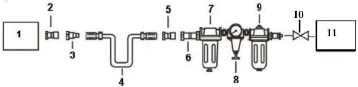
An automatic in-line filter-regulator-lubricator is recommended (Fig 1) as it increases tool life and keeps the tool in sustained operation. The in-line lubricator should be regularly checked and filled with air tool oil.
Proper adjustment of the in-line lubricator is performed by placing a sheet of paper next to the exhaust ports and holding the throttle open approximately 30 seconds. The lubricator is properly set when a light stain of oil collects on the paper. Excessive amounts of oil should be avoided.
POWAIR0805 EN
In the event that it becomes necessary to store the tool for an extended period of time (overnight, weekend, etc.), it should receive a generous amount of lubrication at that time. The tool should be run for approximately 30 seconds to ensure oil has been evenly distributed throughout the tool. The tool should be stored in a clean and dry environment.
- It is most important that the tool be properly lubricated by keeping the air line lubricator filled and correctly adjusted. Without proper lubrication the tool will not work properly and parts will wear prematurely.
- Use the proper lubricant in the air line lubricator. The lubricator should be of low air flow or changing air flow type, and should be kept filled to the correct level. Use only recommended lubricants, specially made for pneumatic applications. Substitutes may harm the rubber compounds in the tools, O-rings and other rubber parts.
8 IMPORTANT!!!
If no filter/ pressure regulator/ lubricator is installed in the compressed air system, then pneumatic tools must be lubricated with 2 to 6 drops of oil at least once a day or after every two hours of use. This must be done directly along the male coupler or the screw (OIL) provided for the purpose on the side of the tool's housing.
Automatic lubrication is also possible using the supplied mini oiler that you have to install between the threaded connector of the tool and the male coupler. Make sure that the oiler is always filled with suitable oil.
Fig. 1
-
Tool
-
Quick connector
-
Quick coupler
-
Air hose
-
Quick connector
-
Quick coupler
-
Lubricator
-
Regulator (0-8.5 bar)
-
Filter
-
Cut-off valve
-
Air compressor
9 LOADING AND OPERATION
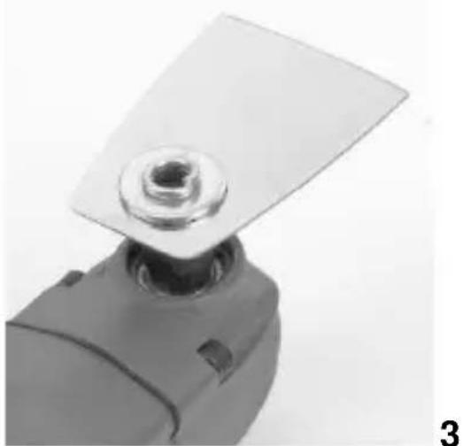
9.1 Installing accessories (Fig. 2)

ATTENTION! Always remove the hose leading to the compressor first before changing accessories.
Select the accessory suitable for the job.
- Insert the selected tool into the provided connection of the compressed air multitool. You may adjust the accessory to the desired alignment in 30° increments using the setting pins.
- First place the washer onto the accessory and then place the spring ring over it.
- Now take the Allen screw and tighten using the included Allen key. Use the counter wrench to fix the appliance while tightening the Allen screw.
9.2 Switching on/off

Verify the equipment is correctly connected and the hose properly seated.
- Pull the trigger to start the machine
■ Release the trigger to stop the machine
9.3 Selecting the Application Tool/Accessory
| Accessory | Material | |
Plunge cut saw blade wood | Wooden materials, plastic, gypsum and other soft materials. | |
Segment saw blade with recess | Wooden materials and plastic. | |
| Segment saw blade flat |  | Wooden materials, plastic, non-ferrous metals. |
Shovel blade |  | Wood, paint, carpet adhesive, silicone and other elastic materials. |
| Base plate for sanding |  | Depends on sanding sheet |
10 MAINTENANCE

WARNING: Disconnect wrench from air supply before changing accessories, servicing or performing maintenance. Replace or repair damaged parts. Use genuine parts only. Non-authorised parts may be dangerous.
- Lubricate the air wrench daily with a few drops of air tool oil dripped into the air inlet
- DO NOT use worn or damaged sockets.
- Loss of power or erratic action may be due to the following:
- Excessive drain on the air line. Moisture or restriction in the air pipe. Incorrect size or type of hose connectors. To remedy check the air supply and follow instructions.
- Grit or gum deposits in the wrench may also reduce performance. If your model has an air strainer (located in the area of the air inlet), remove the strainer and clean it.
- When not in use, disconnect from air supply, clean wrench and store in a safe, dry, childproof location.
11 TECHNICAL DATA
| Model | POWAIR0805 |
| No load speed | 18000 min ^-1 |
| Air pressure | 6.2 bar / 90 psi |
| Air inlet size | 14" |
| Avg. air consumption | 180 l/min |
12 NOISE
Noise emission values measured according to relevant standard. (K=3)
| Acoustic pressure level LpA | 88 dB(A) |
| Acoustic power level LwA | 99 dB(A) |

ATTENTION! Wear hearing protection when sound pressure is over 85 dB(A).
aw (Vibration) :
4,5 m/s²
13 TROUBLESHOOTING
The following form lists the common operating system with problem and solutions. Please read the form carefully and follow it.

WARNING: If any of the following symptoms appears during your operating, stop using the tool immediately, or serious personal injury could result. Only a qualified persons or an authorized service center can perform repairs or replacement of tool.
| PROBLEMS | POSSIBLE CAUSES | REMEDIES |
| Tool runs at normal speed but loses under load | Motor parts worn. | Lubricating clutch housing.Check for excess clutch oil. Clutch cases need only be half full. Overfilling can cause drag on high speed clutch parts, i.e. a typical oiled/lubricated wrench requires 1/2 ounce of oil. GREASE LUBRICATED:NOTE: Heat usually indicates insufficient grease in chamber. Severe operating conditions may require more frequent lubrication. GREASE LUBRICATED:NOTE: Heat usually indicates insufficient grease in chamber. Severe operating conditions may require more frequent lubrication. |
| Cam clutch worn or sticking due to lack of lubricant. | ||
| Tool runs slowly. Air flows slightly from exhaust | Motor parts jammed with dirt particles | Check air inlet filter for blockage.Pour air tool lubricating oil into air inlet as per instructions.Operate tool in short bursts quickly reversing rotation back and forth where applicable.Repeat above as needed. |
| Power regulator in closed position | ||
| Air flow blocked by dirt. | ||
| Tools will not run. Air flows freely from exhaust | One or more motor vanes stuck due to material build up. | Pour air tool lubricating tool into air inlet. Operate tool in short bursts of forward and/or reverse rotation where applicable.Tap motor housing gently with plastic mallet.Disconnect supply. Free motor by rotating drive shank manually where applicable |
| Tool will not shut off | ‘O’ rings throttle valve dislodged from seat inlet valve. | Replace ‘O’ ring. |

Note: Repairs should be carried out by a qualified person.
14 ENVIRONMENT
Should your appliance need replacement after extended use, do not discard it with the household rubbish but dispose of it in an environmentally safe way.
15 DECLARATION OF CONFORMITY


VARO N.V. - Joseph Van Instraat 9 - BE2500 Lier - BELGIUM, declares that,
product: PNEUMATIC MULTI-USE TOOL
trade mark: POWERplus
model: POWAIR0805
is in conformity with the essential requirements and other relevant provisions of the applicable European Directives, based on the application of European harmonized standards. Any unauthorized modification of the apparatus voids this declaration.
European Directives (including, if applicable, their amendments up to the date of signature);
2006/42/EC
European harmonized standards (including, if applicable, their amendments up to the date of signature);
The undersigned acts on behalf of the company CEO,
Hugo Cuypers
Certification Manager
Date: 27/02/2014
POWAIR0805 DE
DRUCKLUFT MULTITOOL POWAIR0805
1 EINSATZBEREICH
Modell-No: POWAIR0805
natural_image
Close-up of a black plastic mechanical component with a flat blade and flange (no text or symbols visible)natural_image
Close-up of a mechanical component with a curved black base and a metallic handle (no visible text or symbols)3 PAKKENS INNHOLD....2
4 SIKKERHETSREGLER ....3
4.1 Fare for utslyngede deler .... 4
4.2 Fare for innvikling....4
2 BESKRIVELSE (FIG. A)....2
3 MEDF∅LGENDE INDHOLD....2
4 SIKKERHEDSFORSKRIFTER 3
TRYKLUFTDREVET MULTIVÆRKT∅J POWAIR0805
1 ANVENDELSE
3 FÖRPACKNINGSINNEHÅLL 2
4 SÄKERHETSFÖRESKRIFTER 3
3 FÖRPACKNINGSINNEHÅLL
natural_image
Close-up of a mechanical component with a black bolt and gray base (no visible text or symbols)11 TEKNISET TIEDOT 8
12 MELU....8
13 VIANETSINTÄ 8
14 LAITTEEN KÄYTÖSTÄ POISTAMINEN....10
15 YHDENMUKAISUUSILMOITUS....10
PAINEILMAKÄYTTÖINEN MONITOIMITYÖKALU POWAIR0805
1 KÄYTTÖ
9 OPTEREĆENJE I RAD....6
9.1 Postavljanje nastavaka (slika 2)....6
4 SIGURNOSNA PRAVILA
natural_image
Close-up of a mechanical component with a black circular base and metallic handle (no visible text or symbols)Ovisno o brusnom listu
10 ODRŽAVANJE

9 OPTEREĆENJE I RAD....6
9.1 Montiranje pribora (Sl. 2)....6
natural_image
Close-up of a mechanical component with a triangular base and central knob (no visible text or symbols)9 VOLBA PŘÍSLUŠENSTVÍ A PROVOZ....6
natural_image
Close-up of a mechanical component with a black bolt and gray base (no visible text or symbols)natural_image
Close-up of a mechanical component with a black base and metallic handle (no visible text or symbols)v závislosti od brúsneho listu
Brúsna doska na brúsne listy
10 ÚDRŽBA

natural_image
Close-up of a mechanical component with a black base and metallic handle (no visible text or symbols)10 KARBANTARTÁS

natural_image
Exterior view of a metallic industrial power tool with attached bracket (no visible text or symbols)
WWW.VARO.COM
DESIGNED AND MARKETED BY VARO
©copyright by varo
VARO - VIC. VAN ROMPUY nv
JOSEPH VAN INSTRAAT 9 - 2500 LIER - BELGIUM
OFFICES: