Bolero Squad GI 3500 Hybrid FullFlex - Cooker CECOTEC - Free user manual and instructions
Find the device manual for free Bolero Squad GI 3500 Hybrid FullFlex CECOTEC in PDF.

| Product type | Built-in mixed hob (gas and induction) |
| Brand | Cecotec |
| Model | Bolero Squad GI 3500 Hybrid FullFlex |
| Product reference | EU01_100498 |
| Built-in dimensions (W x D) | 560 x 480 mm |
| Power supply | AC 220-240 V, 50/60 Hz, 3.5 kW |
| Compatible gas type | Natural gas G20 (20 mbar); adaptable LPG G30 (30 mbar) |
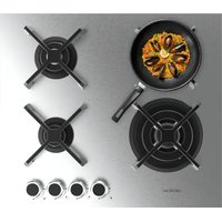
| Gas burners | 4 burners: auxiliary, semi-rapid, rapid, triple ring wok (3.4 kW) |
| Induction zones | Top zone ∅180 mm (2000-2300 W), bottom zone ∅180 mm (1500-1800 W) |
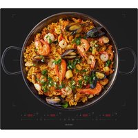
| FullFlex zone | 2500-2800 W, usable as a single zone or two independent zones |
| Induction functions | Booster, Keep warm, Timer (99 min), Pause, Child lock, Automatic shut-off, Overflow protection |
| Gas safety | Thermocouple safety system (automatic shut-off in case of extinction) |
| Residual heat indicator | Yes, for each induction zone |
| Surface material | Ceramic glass |
| Cleaning | Removable washable grates and burners; ceramic glass surface cleaned with specific product and soft cloth |
| Box contents | Mixed hob, instruction manual, mounting accessories (depending on model) |
| Manufacturer | Cecotec Innovaciones, S.L., Av. Reyes Católicos, 60, 46910, Alfafar, Valencia (Spain) |
| Compliance | EU directives: low voltage, electromagnetic compatibility, gas appliances |
Frequently Asked Questions - Bolero Squad GI 3500 Hybrid FullFlex CECOTEC
User questions about Bolero Squad GI 3500 Hybrid FullFlex CECOTEC
0 question about this device. Answer the ones you know or ask your own.
Ask a new question about this device
Download the instructions for your Cooker in PDF format for free! Find your manual Bolero Squad GI 3500 Hybrid FullFlex - CECOTEC and take your electronic device back in hand. On this page are published all the documents necessary for the use of your device. Bolero Squad GI 3500 Hybrid FullFlex by CECOTEC.
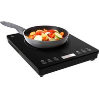
USER MANUAL Bolero Squad GI 3500 Hybrid FullFlex CECOTEC
natural_image
3D rendering of a gas stove with cooling fan and mounted platform (no visible text or symbols)- Parts and components 26
- Before use 26
- Installation 26
- Operation 34
- Cleaning and maintenance 39
- Problem solving 40
- Technical specifications 43
SOMMAIRE
EN • The coding in this manual is generic and applies to all code variants of the appliance.
- 3.4 kW triple-crown wok burner
- Upper cooking zone ∅ 180 mm (2000-2300 W)
- Lower cooking zone ∅ 180 mm (1500-1800 W)
- Induction hob control panel
-
Spark plug (some models only)
-
Thermocouple safety system (only on some models): activates if the burner flame is accidentally extinguished (by spillage, draught, etc.), automatically cutting off the gas supply.
-
Burner control knob
-
FullFlex Zone (2500-2800 W)
NOTE:
The graphics in this manual are schematic representations and may not exactly match the product.
2. BEFORE USE
- This appliance has packaging designed to protect it during transport. Remove the appliance from its box and remove all packaging material. You can store the original box and other packaging in a safe place to prevent damage to the appliance if you need to transport it in the future. If you wish to dispose of the original packaging, be sure to recycle all items properly.
- Make sure that all parts and components are included and in good condition. If any of them are missing or not in good condition, please contact the official Cecotec Technical Service immediately.
Contents of the box
- Appliance
- Instruction manual
- Mounting accessories (depending on model)
3. INSTALLATION
Warning: The following instructions are for use by a qualified technician. Disconnect the power supply before performing any cleaning or maintenance work.
Placement of the gas hob
This appliance should only be installed and used in well ventilated areas.
- Ensure that the room is fitted with a mechanical ventilation device (extractor hood) that allows smoke and combustion gases to escape to the outside.
Legend Figure 2:
- Through a chimney or flue.
-
Directly to the outside.
-
Ensure that the installation site allows fresh air circulation and fresh air intake. A minimum air flow rate of 2 m^3/h per kW of installed gas power is required. The air will enter through an external duct with a diameter of at least 100 cm^2 . Make sure it is not obstructed. For models without a thermocouple safety system, the room must be fitted with a ventilation duct with twice the diameter. (Fig. 3) Alternatively, the room can be ventilated indirectly via adjoining rooms (with ventilation ducts leading to the outside). If the above requirements are not met, there is a risk of fire (Fig. 4).
Legend Figure 3:
- Adjoining room.
- Ventilation ducts to evacuate combustion gases.
Legend Figure 4:
- Room to be ventilated.
-
Extending the ventilation distance between the window and the ground
-
In case of intensive and prolonged use of the appliance, additional ventilation (e.g. opening a window) or more effective ventilation (e.g. increasing the power of mechanical ventilation, if available) will be necessary.
- Liquefied petroleum gases (LPG) are heavier than air, so they tend to concentrate in lower places where there is no good ventilation. Rooms where LPG tanks are installed must be ventilated to the outside to prevent gas leakage.
Therefore, these tanks should not be installed or stored in rooms or spaces below ground level (basements, etc.). It is recommended to keep only the currently operating tank in the room and to ensure that it is not near any heat source (furnaces, fireplaces, cookers, etc.).
Gas hob fitting
The gas hob is designed with an overheating protection device, so the appliance can be installed next to worktops. However, make sure that the height of the worktops does not exceed the height of the hob.
For proper installation, the following precautions should be taken:
- The hob can be installed in a kitchen, dining room or living room, but not in a bathroom.
- Furniture near the appliance that is higher than the height of the worktop must be placed
at least 110 mm away from the edge of the hob.
- Cabinets near the cooker hood must have a minimum height of 420 mm above the worktop (Fig. 5).
Legend Figure 5:
- Extractor Hood
-
min 650 with extractor hood; min 700 without hood.
-
If the hob is installed under a cabinet, the cabinet must be at least 700 mm away from the worktop (Fig. 6).
Legend Figure 6:
- Distance required for the installation of the hob without extractor hood.
- Distance required for the installation of the plate under a cooker hood.
- Hook position for a 20 mm thick worktop.
- Hook position for a 30 mm thick worktop.
- Hook position for a 40 mm thick worktop.
| Installation dimensions A | (mm) B (mm) | |
| 560 480 |
- If the gas hob is not installed on a built-in oven, a wooden panel must be inserted to insulate it. This panel must be placed at a minimum distance of 20 mm from the bottom of the hob. On the other hand, if the hob is installed on a built-in oven, the oven must be placed on two wooden strips. If it is placed on a board, remember to leave a space of at least 45 x 560 mm between the board and the back of the oven (Fig. 7).
When installing the hob on an unventilated built-in oven, make sure that it has air inlets and outlets to adequately ventilate the inside of the unit.
- The distance between the bottom of the plate and the board must comply with the dimensions shown in the figure (min. 50 mm).
- To ensure correct operation of the appliance and to allow air to escape, leave a minimum gap of 20 mm between the hob and the worktop (Fig. 8).
Gas connection
The hob must be connected to the gas supply by a qualified technician. During installation, it is essential to install an approved gas cock to isolate the supply to the hob and facilitate its subsequent removal or maintenance. The connection of the hob to the natural gas or LPG network must be carried out in accordance with current regulations and only after checking that it can be adapted to the type of gas to be used. If this is not the case, follow the instructions indicated in the section "Adaptation to different types of gas". In the case of LPG tank connection, use pressure regulators that comply with the regulations in force.
Important: For correct regulation of gas use and longer hob life, ensure that the gas pressure is set to the values indicated in the table "Burner and nozzle specifications".
Connection with rigid pipe (copper or steel)
- The connection to the gas supply must be made in such a way that no stress points are created on any part of the gas hob.
- The plate is equipped with a gas supply elbow and gasket.
- Remove the elbow and replace the gasket.
- Use a 1/2" threaded elbow to connect the gas plate to the cylinder.
Connection with a metal hose
- Use a 1/2" threaded elbow to connect the gas plate to the pipe. Only use pipes and sealing gaskets that comply with current regulations. The maximum length of the flexible hoses must not exceed 2000 mm. Once the connection has been made, make sure that the metal hose does not touch any moving parts and is not crushed.
Tightness check
- Once the hob has been installed, check the gas connections for leaks using soapy water (never fire).
Electrical connection
The gas hob is equipped with a three-pole power cable designed for use with alternating current, in accordance with the indications on the rating label located underneath the hob. The earth wire is yellow and green in colour.
In the case of installation on a built-in oven, the electrical connections of the hob and the oven must be separate, not only for safety, but also for convenience when removing them in the future.
Electrical connection of the gas hob
Connect the power supply cable to a standard socket compatible with the wattage indicated on the rating plate or connect it directly to the mains. In the latter case, a single-pole switch must be fitted between the gas hob and the mains, with a minimum contact separation of 3 mm. Do this in accordance with current safety regulations (the switch must not interrupt the earth line). The power cable must be positioned in such a way that it never reaches a temperature of more than 50°C with respect to the ambient temperature.
Before making the connection, make sure that:
- The fuse and power supply can withstand the power required by the gas hob.
- The electrical supply system is provided with an earthing system that complies with current regulations.
- The plug or switch is easily accessible.
The wires of the main cable are colour coded as follows:
Green/Yellow = Earth
Blue = Neutral
Brown = Phase
In case the colours of the wires do not match the colours of the terminals of your plug:
- Connect the green/yellow wire to the "E" terminal, or green or green and yellow.
- Connect the brown wire to the "L" or red terminal.
- Connect the blue wire to the "N" or black terminal.
*Colours may vary depending on the model.
Table 1: Burner and injector specifications Adaptation of the gas hob according to the gas type
| Natural gas G20 Butane | G30 | |||
| Burner | Thermal load (kW) | Injector 1/100 (mm) | Thermal load (kW) | Injector 1/100 (mm) |
| Auxiliary 1 71 1 52 | ||||
| Semi-fast 1,80 97 1,80 67 | ||||
| Quick 2,40 110 2,40 | 77 | |||
| Triple crown wok | 3,40 | 125 | 3,40 | 93 |
| Supply pressure | 20 mbar | 30 mbar | ||
At 15 °C and 1013 mbar - dry gas
| P.C.I.G20 | 37.78 MJ/m3 | P.C.I.G25.1 | 32.51 MJ/m3 |
| P.C.I.G25 | 32.49 MJ/m3 | P.C.I.G27 | 30.98 MJ/m3 |
| P.C.I.G2.350 | 27.20 MJ/ m3 | P.C.I.G30 | 49.47 MJ/kg |
Replacing the burner injector: Loosen the injector with a suitable tool (Figure 9).
Fit the new injector on the burner according to the type of gas used (see table 1).
Note: After adapting the hob connection to another type of gas, be sure to place a label on the appliance containing this information.
Table 2: Change of gas type Gas flow regulation via the valve
| Burner Call | Switching from LPG to natural gas | Switching from natural gas to LPG | |
| Burners | Long flame | Replace the injector of the burner according to the instructions in Table 1. | Replace the injector of the burner according to the instructions in Table 1. |
| Short call | Turn the adjusting screw (Fig. 7) to regulate the flame. | Turn the adjusting screw (Fig. 7) to regulate the flame. |
Valve and gas flow adjustment
To adjust the gas valve and regulate the flame, first turn the control knob to the minimum position.
Remove the knob and adjust the flame with a small screwdriver (Fig. 10).
To check whether the flame has reached the desired intensity, light the burner at the maximum position for 10 minutes. Then turn the knob to the minimum position. The flame should not go out or move towards the injector. If this happens, readjust the gas valve.
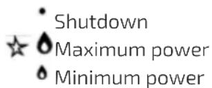
Flame selection
If combustion is taking place efficiently, the colour of the flame should be deep blue on the outside and slightly lighter on the inside. The size of the flame depends on the position of the corresponding knob (Fig. 11).
Legend Figure 11:
- Long flame (maximum power)
- Short flame (minimum power)
- Shutdown
See figure 11 for the different operating positions (flame size selection). When cooking starts, turn the knob to the maximum position to activate the long flame. This will heat the pan more quickly. Then turn the knob to the minimum position to activate the short flame and maintain cooking. It is recommended to adjust the flame size progressively.
Please observe the following energy saving tips:
- Use the plate correctly.
- Choose the right burner for the size of the vessel.
-
Use appropriate cooking utensils.
-
Up to 60% of energy is saved when using suitable cooking utensils.
- Up to 60% of energy is saved when the hob is used correctly and the right flame size is chosen.
- In order for the hob to operate efficiently and consume less energy, it is essential to keep the burners clean (especially the flame openings and nozzles).
Table 3: Adaptation to different types of gas
Equipment class: I_2E I_2E I_2E+I(2L) I_(2H5) I_2ELS I_2ELW I_3+ I_3B/P I_3B/P I_3B/P I_(3B/P) I_3P I_2H3+ II_2E3B/P II_(2HS3B/P) II_2ELWLS3B/P II_2ELL_3B/
| Burner | Type of gas | Supply pressure | Injector diameter | Rated thermal load | Reduced thermal load | ||||
| mbar 1/100 | mm g/h l/h | kW kcal/h | kW kcal/h | ||||||
| Auxiliary | Natural gas G20 | 20 71 - 95 | 1860 0,40 344 | ||||||
| Butane G30 | 30 52 72,6 | -1 860 0,40 | 344 | ||||||
| 37 | 47 72,6 - 1 | 860 0,40 | 344 | ||||||
| 50 45 72,6 | -1 860 0,40 | 344 | |||||||
| Semi-fas | Natural gas G20 | 20 | 97 | - | 171 | 1,8 | 1548 | 0,60 | 516 |
| Butane G30 | 30 | 67 | 130,8 | - | 1,8 | 1548 | 0,60 | 516 | |
| 37 | 64 | 130,8 | - | 1,8 | 1548 | 0,60 | 516 | ||
| 50 | 59 | 130,8 | - | 1,8 | 1548 | 0,60 | 516 | ||
| Quick | Natural gas G20 | 20 | 110 | - | 228 | 2,4 | 2064 | 0,90 | 774 |
| Butane G30 | 30 | 77 | 174 | - | 2,4 | 2064 | 0,90 | 774 | |
| 37 | 73 | 174 | - | 2,4 | 2064 | 0,90 | 774 | ||
| 50 | 67 | 174 | - | 2,4 | 2064 | 0,90 | 774 | ||
| Triple crown wok | Natural gas G20 | 20 125 - 32 | 3,4 2924 1 | 50 1290 | |||||
| Butane G30 | 30 93 247 | - 3,4 2924 1,50 1290 | |||||||
| 37 88 247 | - 3,4 2924 1,50 1290 | ||||||||
| 50 82 247 | - 3,4 2924 1,50 1290 | ||||||||
Table 4: Gas supply and ranking by country
| Gas category Supply | pressure Country | |
| I2H G20 20 mbar | AT, BG, CZ, DK, EE, FI, GR, HR, HU, IS, IS, IE, IT, LV, LT, NO, PT, RO, SK, SI, ES, SE, CH, TR, GB | |
| I2E G20 20 mbar | DE, LU | |
| I2E+ | G20/G25 20/25 mbar | BE, FR |
| I2L | G25 25 mbar | NL |
| I2HS | G20/G25.1 25 mbar | HU |
| I2ELS | G20 20 mbar, G2.350 13 mbar | PL |
| I2ELW | G20/G27 20 mbar | PL |
| I3+ | G30-G31 (28-30)-37 mbar | BE, CY, CZ, EE, FR, GR, IE, IT, LT, LU, LV, PT, RO, SK, ES, CH, GB |
| I3B/P | G30 30 mbar | BE, CY, CZ, DK, EE, FI, FI, GR, HR, LV, LT, LU, MT, NL, NO, SK, SI, SE, TR |
| I3B/P | G30 37 mbar | PL |
| I3B/P | G30 50 mbar | AT, DE, HU, CH |
| I3P G31 37 mbar | CH, FR, GR, IE, ES, GB | |
| I2H3+ | G20 20 mbar, G30-G31 (28-30)-37 mbar | GR, IE, IT, PT, ES, GB, CH, CZ, SI, SK |
| II2E3B/P | G20 20 mbar, G30 30 mbar | RO |
| II2HS3B/P | G20/G25.1 25 mbar, G30 30 mbar | HU |
| II2ELWLS3B/P | G20/G27 20 mbar, G2.350 13 mbar, G30 37 mbar | PL |
| II2ELL3B/P | G20 20 mbar, G25 25 mbar, G30 50 mbar | DE |
This gas hob complies with the following European Economic Community directives:
- 73/23/EEC of 19/02/73 (electrical equipment designed for use within certain voltage limits) and subsequent amendments.
- 89/336/EEC of 03/05/89 (electromagnetic compatibility) and subsequent amendments.
- 90/396/EEC of 29/06/90 (appliances burning gaseous fuels) and subsequent amendments.
- 93/68/EEC of 22/07/93 and subsequent amendments.
- Regulation (EU) 2016/426.
- Low Voltage Directive 2014/35/EU.
- EC Council Directive 2014/30/EU.
4. OPERATION
1. Gas hob
The output of the gas burner can be adjusted with the corresponding control knob using one of the following settings:
On models with thermocouple safety system
Press and turn the knob to light the burner. Hold it firmly for about 6 seconds after the flame has ignited.
On models with spark plug
First press the electronic ignition button, identified by the symbol, then press the corresponding knob and turn it counterclockwise to the maximum power position.
Lighting the burner
Press the corresponding knob and turn it anticlockwise to the maximum power position. Keep it pressed until sparks are produced and the burner flame ignites.
Warning: If the flame is accidentally extinguished during operation, turn off the gas supply with the control knob and wait at least one minute before relighting the burner.
Switching off the burner
Turn the corresponding knob clockwise to the “-” position.
Containers suitable for gas burners
To save energy and avoid damage, please follow the instructions below:
- Use utensils of a suitable size for each burner (see table). Make sure that the flame does not touch the sides of the pan.
- Use flat-bottomed utensils and be sure to always cook with the lid on.
- The recommended cooking settings (maximum, medium or minimum power) depend on the use and type of food, as well as the material of the containers used.
| Burner 0 Diameter of utensil (cm) | |
| Auxiliary burner 10-14 | |
| Semi-fast burner 16-20 | |
| Fast burner 22-24 | |
| Triple crown wok burner 24-26 |
2. Induction hob
Warning: Induction cooking zones will not light up if the pot size is not suitable. Only use pots with the induction symbol. Place the pan on the desired cooking zone before switching on the hob.
Induction-safe vessels
To check whether a cookware is suitable for induction, simply use a magnet. If the magnet sticks to the base, it means it is suitable.
- Cookware made of the following materials is not suitable for induction: pure stainless steel, aluminium or copper without magnetic base, glass, wood, porcelain, ceramic and earthenware.
-
Use containers with a flat base, otherwise the surface of the glass may become scratched.
-
To avoid permanent damage to the induction hob, make sure that the pan is not deformed.
- Do not place the container on the control panel when it is still hot. This could damage it.
- The diameter of the base of the utensils must be at least 10 cm.
Control panel (Fig. 12)
- Upper cooking zone indicator 180 mm (d) 2000/2300 W (Booster)
- Lower zone indicator 180 mm (d) 1500/1800 W (Booster)
- FullFlex 2500/2800 W zone indicator (Booter)
- Pause function 8
- Timer
- Keep Warm function
- Power level/timer adjustment slide control
- Booster function
- Child lock function
- ON/OFF touch icon
Switching the induction hob on and off
To switch on the induction hob, press and hold the On/Off touch icon for a few seconds until the cooking zone indicators light up (Fig. 13).
Adjusting the power level
Once the induction hob has been switched on, place the pan on the desired cooking zone.
Then press the corresponding touch icon and the indicator for the selected cooking zone will flash. To adjust the power level, simply slide your finger over the slider.
Child Lock
- This function allows you to lock the control panel to prevent children from accidentally switching on the induction hob.
- To activate this function and lock the controls, press the corresponding touch icon and the timer display will show "Lo".
- To deactivate the child lock, switch on the induction hob and press and hold the corresponding touch icon for a few seconds.
The timer display will stop showing "Lo" and you will be able to use the control panel normally.
Timer
- The timer allows you to set the cooking time up to a maximum of 99 minutes on all cooking zones.
- Select the cooking zone in which you want to activate the timer. Then press the corresponding touch icon. The timer display will show "10" and the "0" will start flashing.
Use the slider to adjust the cooking time.
- Press the timer touch icon again, the "1" will start flashing and you can adjust the cooking time using the slider.
- The countdown will start after a few seconds.
- Once the programmed time has elapsed, the induction hob will emit an acoustic signal and the timed cooking zone will switch off automatically.
- To deactivate the timer, select the timed cooking zone and press the corresponding touch icon. Then set the cooking time to "00" using the slider.
Booster function
- To activate this function, select the desired cooking zone and then press the corresponding touch icon. Once the function is activated, the indicator of the selected cooking zone will show "b" and the Booster function will apply the maximum power.
- Keep warm function
- This function automatically sets a suitable power level to keep cooked food warm. To activate it, select the desired cooking zone and then press the corresponding touch icon. Once the function is activated, the indicator of the selected cooking zone will show "c".
Pause function
- To stop the cooking process and keep the selected settings, press the pause touch icon. The indicators of all cooking zones will show "P" and stop heating.
- When the function is activated, you can only use the touch icons for pause, on/off and child lock.
- Press the pause touch icon again to resume the cooking process with the previous settings.
FullFlex Zone
- It can be used as a single cooking zone or as two different zones, depending on your needs.
- It consists of two independent inductors which can be controlled separately. If the FullFlex zone is used as a single cooking zone, the cookware can be moved from one zone to another while maintaining the same power level as the zone where the cookware was originally placed (this zone will automatically switch off).
- If you use this zone as an individual cooking zone, be sure to place the utensil in the centre.
Examples of how to place and not to place utensils (Fig. 14).
Overflow protection
If any liquid is spilled on the control panel while the induction hob is in operation, the induction hob will automatically switch off after 10 seconds.
Automatic safety shutdown
The induction hob will switch off automatically if the cooking time is not set, if you have forgotten to switch it off or when it is not in use. The default operating times for different power levels are shown in the table below:
| Power level c 1 3 4 5 6 7 8 9 | |||||||||
| Default operating time (hours) 8 8 8 4 4 | 4 2 | 2 2 |
Control panel indicators
Residual heat indicator
- The induction hob has a residual heat indicator on each cooking zone.
- This indicator lets you know when the cooking zone is still hot.
- When the display shows , this means that the cooking zone is still hot.
- If the residual heat indicator for a particular cooking zone is lit, that zone can be used, for example, to keep food warm or to continue cooking with the residual heat.
- When the cooking zone cools down, the indicator will go out.
Vessel not detected indicator
- The symbol will appear on the display when you use a non-induction cookware, the cookware is not positioned correctly or its base is not of the correct diameter. If it takes more than 120 seconds to place the pan, the induction hob will switch off automatically.
Practical advice
Appropriate utensils
For best performance, follow these guidelines:
- Use the appropriate cookware for each cooking zone (see table).
- Always use flat-bottomed cookware and keep it covered.
- When the contents come to the boil, turn the knob to the minimum power position.
| Burner 0 Diameter of utensil (cm) | |
| Auxiliary burner 10-14 | |
| Semi-fast burner 16-20 | |
| Fast burner 22-24 | |
| Triple crown wok burner 24-26 | |
| Induction cooking zone ∅ 180 mm 10-20 | |
| FullFlex cooking zone 10~20 x 25~40 |
5. CLEANING AND MAINTENANCE
Cleaning the induction hob
- Do not use steamers to clean the induction hob.
- Before cleaning, make sure that the cooking zones are switched off and that the residual heat indicator ("H") is not displayed.
Warning: Do not use abrasive sponges or scouring pads. Their use may scratch the surface of the glass.
- After each use, allow the plate to cool and clean it to remove food residues and stains.
- Remove any salt or sugar residues immediately, as they could scratch the surface of the glass.
- Clean the induction hob with a soft cloth, kitchen paper or specific cleaning product (follow the manufacturer's instructions).
Cleaning the gas hob
Before carrying out any cleaning or maintenance work, disconnect the gas hob from the mains. To prolong the service life of the gas hob, it is essential to clean it regularly. When doing so, please note the following:
- The enamelled parts and the glass surface should be cleaned with lukewarm water.
Avoid using abrasive cleaning agents or corrosive substances that may damage the enamel or scratch the glass. - The removable burner components should be washed with warm soapy water after each use. Be sure to remove any encrusted food residue.
- The automatic spark plug must be cleaned periodically with a non-metallic brush. After cleaning, make sure that ignition occurs normally.
- The surface of stainless steel and other iron parts can be damaged by contact with water with a high concentration of lime scale or corrosive cleaning products (containing phosphorus). To prolong their service life, it is recommended to rinse them with water and dry them thoroughly to eliminate the presence of drips or other liquids.
- After each use, wipe the surface of the hob with a damp cloth to remove dust or food debris. The glass surface should be cleaned regularly with warm water and non-corrosive cleaning agents.
- Allow the grills to cool slightly. Carefully remove the grills from the gas hob. Place them in the sink and remove any food or grease residue with a non-metallic brush and soapy water. Rinse the grills with water and dry them thoroughly before putting them back in place.
First remove any food or grease residues with a ceramic hob scraper (not included).
While the surface is still warm, use a suitable cleaning agent and kitchen paper to clean it.
Then wipe it with a damp cloth and dry it thoroughly. Remove any remaining aluminium foil or plastic and immediately remove any melted sugar or food with a high sugar content that has been smeared on the surface.
Do not use steel wool pads or aggressive or abrasive cleaning agents such as spray cleaners.
You can use a suitable scraper NOT included (Fig. 15).
Cleaning of gas valves
Over time, it is common for the gas valves to become clogged by a build-up of dirt (burnt grease, food residues, liquids, etc.), which can prevent the gas from escaping. To prevent this from happening, clean the burner orifices and the inside of the gas valves with a degreasing product.
Note: This procedure may only be performed by a qualified technician.
6. PROBLEM SOLVING
In some cases, the faults detected can be easily solved. Before contacting the Technical Assistance Service, check that the gas and electricity supplies have not been cut off.
- Check that there has not been a power failure.
- After cleaning the plate, be sure to dry it thoroughly.
- If, when the board is switched on, an error code appears on the display, refer to the table below.
- If the board cannot be switched off using the on/off touch icon, disconnect it from the mains.
Induction hob
The cooking zones are dirty.
Check that there are no burnt food residues. Be sure to clean the induction hob after each use.
The residual heat indicator does not light up.
If the cooking zone is hot enough and the residual heat indicator does not light up, please contact the official Cecotec Service Centre.
Error codes
| Error code Cause Solution | ||
| U | Vessel not detected Place the pan in the desired cooking zone. | |
| E0 Power supply error | Check the connection or disconnect the power supply.Replace the power supply board. | |
| EA Power supply error | Check the connection or disconnect the power supply.Replace the power supply board. | |
| E1 High blood pressure | Check that there has not been a power failure.Reconnect the appliance to the mains. | |
| E2 Low voltage | Check that there has not been a power failure.Reconnect the appliance to the mains. | |
| E3/E4 Overheating | Allow the induction hob to cool down and switch it on again. | |
| F3/F5F9/FA | Temperature sensor error (short or open circuit) | Please contact the official Cecotec Technical Assistance Service. |
Noises emitted by the induction cooktop
- During cooking, it is normal for the induction hob to make noises such as hissing or crackling noises. Many of these noises occur when using utensils with non-flat bases or utensils made of different materials on top of each other.
- These noises vary depending on the containers used and the amount of food cooked, and do not indicate a fault.
- In addition, the induction hob is equipped with an internal fan which is activated during cooking. This fan will continue to operate after the induction hob is switched off to control the temperature.
- This noise is completely normal and is part of the induction technology.
Gas hob
Burner does not light or flame is not uniform.
Check that:
- Burner orifices are not obstructed.
- All burner parts are correctly positioned.
- No draughts around the burner.
The flame goes out when the control is released.
Check that:
- Press the control knob firmly.
- Hold down the control knob long enough. This will activate the thermocouple gas flow system.
- The orifice of the thermocouple safety system is not obstructed.
The flame is extinguished when the knob is turned to minimum power.
Check that:
- The gas orifices of the burner are not obstructed.
- No draughts around the burner.
- You have correctly turned the knob to the minimum position.
The utensil is unstable on the plate.
Check that:
- The utensil is not deformed and the base of the utensil is completely flat.
- The utensil is well positioned over the centre of the cooking zone.
Gas hob
Burner does not light or flame is not uniform.
Check that:
- The gas orifices of the burner are not obstructed.
- All moving parts of the burners are properly secured.
- No draughts around the burner.
The flame goes out when the control is released.
Check that:
- Press the knob all the way down.
- Hold down the knob long enough to activate the thermocouple.
- The orifice of the thermocouple safety system is not obstructed.
The flame is extinguished when the knob is turned to minimum power.
Check that:
- The gas orifices of the burner are not obstructed.
- No draughts around the burner.
- You have correctly turned the knob to the minimum position.
The utensil is not stable on the plate.
Check that:
- The bottom of the utensil is completely flat.
- The utensil is correctly centred on the burner.
- The grille is not inverted.
7. TECHNICAL SPECIFICATIONS
Product reference: EU01_100498
Product: Bolero Squad GI 3500 Hybrid FullFlex
ERP tables
| Product type Inset gas hob with induction cooktop |  PIN CODE: 2575DN33174 PIN CODE: 2575DN33174 | |
| Class Class 3 | ||
| Manufacturer | CECOTEC INNOVACIONES, S.L. Av. Reyes Católicos, 60, 46910, Alfatar (Valencia) - SPAIN | |
| Voltage/Frequency (Nominal) | AC 220-240 V, 50/60 Hz, 3,5 kW Electrical protection Class I | |
| Reference EU01_100498 | ||||
| Type of gas G20 @ 20mbar | ||||
| Burner type | Wok | Quick | Semi-fast | Auxiliary |
| EE burner 54,5% N/A N/A N/A | ||||
| EE gas hob | 54,5% | |||
The gas hob is configured to operate on natural gas and the Energy Efficiency calculations have been made for natural gas. If the modification is made for LPG (butane/propane), the Energy Evidence values may be modified.
| Symbol Value | Unit | ||
| Model identification | EU01_100498 Bolero Squad GI 3500 Hybrid FullFlex | ||
| Type of cooktop | Inset gas hob with induction cooktop | ||
| Number of selectors of the lamps and/or cooking zones | 2 | ||
| Zone 1 Upper right zone | |||
| Heating technology (induction hotplates and cooking zones, induction hotplates, induction cooking zones and induction cooking zones) radiation, solid plates) | Induction cooking zones and cooking zones | ||
| Symbol Value Unit | |||
| For circular cooking spots or cooking zones: diameter of the usable surface of each spotlight from electric firing, rounded off to the nearest 5 mm | ∅ 180 mm | ||
| For non-circular cooking spots or cooking zones: width and length of the usable surface of each cooking area spot or electric cooking zone, rounded off to the nearest 5 mm | L | - | mm |
| W - | |||
| Energy consumption per lamp or cooking zone, calculated per kg | ECelectric cooking | 192,7 Wh/Kg | |
| Zone 1 Lower right zone | |||
| Heating technology(induction hotplates and cooking zones, induction hotplates, induction cooking zones and induction cooking zones) radiation, solid plates) | Induction cooking zonesand cooking zones | ||
| Symbol Value Unit | |||
| For circular cooking spots or cooking zones:diameter of the usable surface of each spotlight fromelectric firing, rounded off to the nearest 5 mm | ∅ 180 mm | ||
| For non-circular cooking spots or cooking zones:width and length of the usable surface of each cooking area spot or electric cooking zone, rounded off to the nearest 5 mm | L | - | mm |
| W - | |||
| Energy consumption per lamp or cooking zone, calculated per kg | EC_electric cooking | 192,4 Wh/Kg | |
| Energy consumption of the plate, calculated per kg | EC_electric plate | 192,6 Wh/kg | |
If no cooking zone (induction) is in operation, the hob will automatically switch off after 1 minute*. Power consumption in off mode is less than 0.48W .
*Without performing any operation on the control panel.
Technical specifications may change without prior notification to improve product quality. Made in China | Designed in Spain