Bolero Squad G 2400F - Cooker CECOTEC - Free user manual and instructions
Find the device manual for free Bolero Squad G 2400F CECOTEC in PDF.

| Product type | Built-in gas hob |
| Brand | Cecotec |
| Model | Bolero Squad G 2400F |
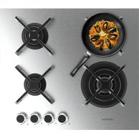
| Number of burners | 4 (auxiliary, semi-fast, fast, triple ring wok) |
| Burner power | Auxiliary 1 kW, Semi-fast 1.8 kW, Fast 2.4 kW, Wok 3.4 kW |
| Power supply | Gas (G20, G30, G31) and electric 220-240 V ~ 50/60 Hz |
| Cutout dimensions | 270 x 480 mm (approx.) |
| Ignition type | Integrated electronic |
| Safety system | Thermocouple (automatic gas shut-off in case of accidental flame extinction) |
| Functions | Electronic ignition, continuous flame adjustment |
| Surface material | Stainless steel |
| Cleaning | Clean burners with warm water and neutral dish soap; avoid abrasive products |
| Maintenance | Regularly clean burner ports and ignition needle |
| Installation | Built-in, requires suitable worktop and adequate ventilation |
| Weight (approx.) | ~10 kg |
| Repairability | Repairs by qualified technician only |
| Spare parts available | Injectors, burners, grates, etc. |
| Warranty | According to applicable regulations; contact Cecotec after-sales service |
Frequently Asked Questions - Bolero Squad G 2400F CECOTEC
User questions about Bolero Squad G 2400F CECOTEC
0 question about this device. Answer the ones you know or ask your own.
Ask a new question about this device
Download the instructions for your Cooker in PDF format for free! Find your manual Bolero Squad G 2400F - CECOTEC and take your electronic device back in hand. On this page are published all the documents necessary for the use of your device. Bolero Squad G 2400F by CECOTEC.
USER MANUAL Bolero Squad G 2400F CECOTEC
natural_image
Top-down view of a black circular vent with cross-shaped blades, mounted on a metallic surface with a small knob (no text or symbols visible)
natural_image
Close-up of a gas stove burner with two flanges and two cross-shaped blades, mounted on a metal frame (no text or symbols visible)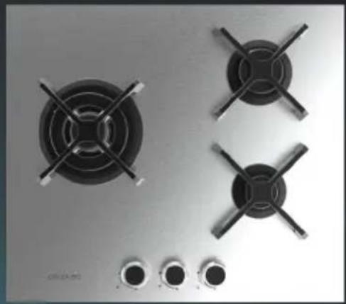
natural_image
Top-down view of a kitchen gas stove with four flanges and three washers (no text or symbols visible)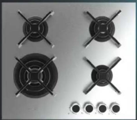
natural_image
Four black gas stove covers arranged on a metallic surface with circular control knobs below (no text or symbols visible)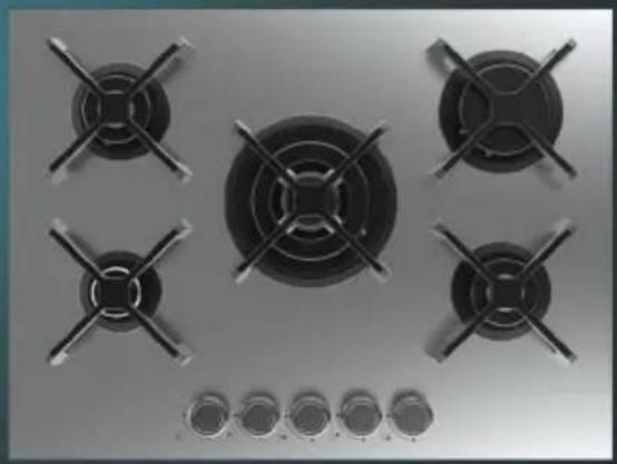
natural_image
Top-down view of a gas stove with six flanges and a central fan (no text or symbols visible)- Parts and components 101
- Before use 101
- Installation 102
- Operation 106
- Cleaning and maintenance 113
- Troubleshooting 114
- Technical specifications 115
- Disposal of old electrical and electronic appliances 117
- Technical support and warranty 117
- Copyright 117
- Declaration of conformity 118
SOMMAIRE
EN • The coding in this manual is generic and applies to all code variants of the appliance.
Before using the appliance, read the following instructions carefully. Keep this instruction manual for future reference or new users.
- The installation and connection of the appliance must be carried out by authorised specialists. The manufacturer is not liable for damage caused by installation or connection errors.
- The appliance must be properly fitted and installed in a suitable and approved kitchen unit and worktop.
- This appliance is designed for domestic use only and is not intended for bars, restaurants, farmhouses, hotels, motels, and offices.
- WARNING: The appliance and its accessible parts may heat up during use. Be careful with the heating elements. Children under 8 years of age should be kept away from the appliance unless continuously supervised.
- CAUTION: Accessible parts may be hot during operation or after use. Keep children away from the appliance when in use.
- Do not allow children to play with the appliance.
- Before installation, make sure that the local distribution conditions (gas type and pressure) are compatible with those of the appliance.
- The setting conditions for this appliance are indicated on the rating plate.
- This gas hob is not connected to any flue-gas evacuation system. It must be installed and connected in compliance with current installation regulations. Pay particular attention to the relevant ventilation requirements.
- WARNING: During use, a gas hob emits heat, moisture, and flue gases into the room where it's located. Make sure that
the room is well ventilated, especially when the hob is in operation. Keep natural ventilation channels open or install a mechanical-ventilation device (for example, an extractor hood).
- Intensive and prolonged use of the appliance may require additional ventilation, e.g. opening a window, or increasing the extractor hood power.
- This appliance can be used by children aged 8 years and people with reduced physical, sensory, or mental capabilities or lack of experience and knowledge if they have been given supervision or instruction concerning use of the appliance in a safe way and understand the hazards involved. Children must not play with the appliance. Cleaning and user maintenance should not be carried out by unsupervised children.
- The appliance is not intended to operate by means of an external timer or a separate remote-control system.
- WARNING: Unattended cooking on a greasy or oily gas hob can be dangerous and may result in a fire. NEVER attempt to extinguish fire with water. Switch off the appliance and cover the flames, e.g., with a fireproof lid or blanket.
- CAUTION: Always supervise the cooking process. Continuously monitor cooking during operation.
- WARNING: Fire hazard. Do not place objects on the cooking surfaces. The appliance could accidentally ignite or still be hot, which means that objects could melt, heat up or catch fire.
- WARNING: Only use the pan supports supplied with the appliance or indicated as suitable by Cecotec. The use of unsuitable pan supports can cause accidents.
-
The appliance must not be installed behind a decorative door to avoid overheating.
-
Do not modify the appliance in any way.
- The gas hob cannot be used as a support or work surface.
- The appliance must be earthed in accordance with local regulations.
- Do not place the appliance on top of a dishwasher or tumble dryer to avoid steam damage.
- Turn off the burners after use.
- Monitor the cooking of very fatty or oily foods to avoid fire.
- Be careful not to burn yourself while or after using the appliance.
- Make sure that no cable of any fixed or mobile appliance touches the burner or hot cookware.
- Never cover the appliance with a cloth or protective film to prevent overheating and fire.
- Make sure the appliance is sufficiently ventilated according to these instructions.
- Do not allow objects of any size to fall onto the appliance.
- Do not leave empty cookware on the burners.
- Never store flammable objects (e.g., aerosols) in the space under the gas hob. Drawers/cabinets and their contents must be heat resistant.
- Precautions in the event of a fault: if you notice a fault, switch off and unplug the appliance.
- Repair of the appliance must be carried out by qualified professionals. Do not try to fix the appliance yourself.
- Always make sure that the cookware is well centred on the burner. The bottom of the cookware should cover the burner as much as possible.
- Always place the cookware on the pan support, never on the burner cap or directly on the burner itself.
-
Intensive and prolonged use of the appliance may require additional ventilation, e.g. opening a window, or increasing the extractor hood power.
-
This appliance is designed for cooking only. It must not be used for other purposes, e.g. for heating rooms.
- Never immerse burner caps or pan supports in cold water. Fast cooling can damage the enamel.
- Always use suitable cookware.
- Regular cleaning of the burner parts is recommended to ensure optimum and safe operation.
- Keep any textiles such as gloves or tea towels away from the burner flame.
- Do not use baking griddles or trays.
- The appliance can only work efficiently if the burner components have been installed correctly, ensuring that cooking utensils (frying pans, pots, pans, among others) can be placed in a stable position.
- Aluminium trays or aluminium foil are not suitable as cooking utensils. Both burner caps and pan supports may be damaged.
- Never flambé under an extractor hood. High flames can cause a fire, even if the extractor hood is switched off.
- When the hob is used for the first time, you will notice some odour, do not worry, this is normal and will disappear with use.
- The appliance must not be placed or used outdoors.
- Do not use the appliance at room temperatures below 5 °C.
- The distance between the frying pan and a non-heat resistant wall should always be more than one centimetre. For shorter distances, the high temperature may cause the wall surface to discolour or warp.
- The burner components are hot during and immediately after use. Do not touch them and avoid contact with non-heat resistant materials.
-
Never open the housing of the appliance.
-
Do not use a pressure washer or steam cleaner to clean the hob.
- Never heat closed cans. Pressure build-up could cause an explosion.
- If you use a worktop protector, make sure it is suitable.
- WARNING! Cecotec accepts no liability for incidents or damage caused by improper use outside the rules set out in this instruction manual, or by non-compliance of these safety instructions and warnings.
- Possible damage produced by incorrect installation, setting or use is not covered by the warranty.
- Cecotec is not responsible for any damage, accident, or incident resulting from the misuse of this device. It is the responsibility of the user to operate and maintain the appliance according to the instructions and recommendations detailed in this manual. Failure to follow instructions may result in personal injury, property damage, or loss of product warranty.
INSTRUCTIONS DE SÉCURITÉ
- 1 kW auxiliary burner
- 1.8 kW semi-rapid burner
- 2.4 kW rapid burner
- 3.4 kW triple-crown wok burner
- Ignition spark plug (only on certain models).
-
Burner control knobs.
-
Thermocouple safety system (only on certain models): activates if the burner flame is accidentally extinguished (due to spillages, draughts, etc.), automatically cutting off the gas supply.
NOTE:
Figure 1 is a general graphical representation of all gas hob models included in this instruction manual.
Each hob may vary in the number and arrangement of burner(s) and control knob(s).
NOTE:
The graphics in this manual are schematic representations and may not exactly match the product.
2. BEFORE USE
- This appliance is packaged in a way as to protect it during transport. Take the appliance out of its box and remove all packaging materials. You can keep the original box and other packaging elements in a safe place. This will help you prevent damage to the machine when transporting it in the future. In case the original packaging is disposed of, make sure all packaging materials are recycled accordingly.
- Make sure all parts and components are included and in good conditions. If there is any piece missing or in bad conditions, contact the official Cecotec Technical Support Service immediately.
Do not remove the serial number of the appliance in order to keep a correct traceability of it in case of assistance.
NOTE:
A. Before installation, make sure that the local distribution conditions (nature of gas pressure) and the appliance setting are compatible.
B. The setting conditions for this appliance are indicated on the rating label.
ENGLISH
C. This gas hob is not connected to a flue-gas evacuation system. It must be installed and connected in compliance with current installation regulations. Particular attention should be given to the relevant ventilation requirements.
D. CAUTION: The use of a gas hob results in the production of heat, moisture and combustion products in the room where it is installed. Make sure the kitchen is well ventilated, especially when the hob is in use: keep natural ventilation openings accessible or install a mechanical ventilation device.
Box content
- Gas hob
- Accessories (burners, caps, pan supports, etc., depending on the model)
- Assembly kit (depending on the model)
- Instruction manual
3. INSTALLATION
Warning: The following instructions are intended for qualified technicians.
Note: Disconnect the power supply before carrying out any cleaning or maintenance tasks.
- Installation must be carried out by a qualified technician.
- The technician must show you the location of the gas valve and how to close it in case of emergency.
- Ensure all packaging materials are removed from the hob before putting it into operation to avoid possible fire hazards.
- Observe the minimum clearances to combustible surfaces indicated in this manual. These must match the information on the rating plate and comply with local regulations and standards.
- If the hob is installed near a window, appropriate precautions must be taken to prevent curtains from blowing over the burners, as this would pose a serious fire hazard.
- When choosing the location of the hob, consider the position of the gas and electricity supply pipes.
- Both the gas supply and electrical power must be closed during installation.
- Do not install another hob next to this appliance.
- Check the underside of the worktop to ensure there are no protrusions. Make sure the worktop is solid, can support the weight of the hob and is level.
- Make sure that the location where you place the hob is well ventilated. Make sure ventilation is not obstructed by bulky objects, etc.
- Remember to glue the sealing gasket to the hob panel before installing it on the worktop.
- RISK OF CUTS. Please note that the edges of stainless steel hobs can cause cuts; extreme caution must be taken when handling.
Placing the gas hob
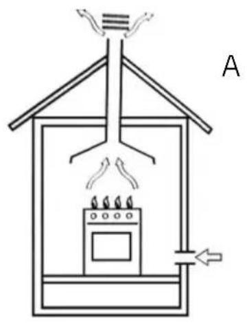
This appliance must only be installed and used in well-ventilated areas.
- Make sure that the room is equipped with a mechanical ventilation device (extractor hood) that allows smoke and combustion gases to be discharged outdoors (Fig. 2).
Fig. 2 key:
A.- Through a chimney or flue.
B.- Directly outdoors.
- Make sure the installation location allows fresh air circulation and intake. A minimum airflow rate of 2 m^3/h per kW of installed gas power is required. Air will enter through an external duct with a diameter of at least 100 cm^2 . Ensure it remains unobstructed.
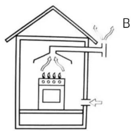
For models without a thermocouple safety system, the room must have a ventilation duct with twice the diameter. for example, minimum 200 cm ^2 . (Fig. 3) Alternatively, the room may be ventilated indirectly through adjacent rooms (provided with ventilation ducts leading outdoors). If the above requirements are not met, there is a risk of fire. (Fig. 4).
Fig. 3 key:
A.- Ventilation ducts for combustion gas evacuation (adjacent room).
Fig. 4 key:
A.- Increased ventilation distance between the window and the floor (room to be ventilated).
-
In case of intensive and prolonged use of the appliance, additional ventilation (e.g., opening a window) or more effective ventilation (e.g., increasing the power of mechanical ventilation, if available) will be necessary.
-
Liquefied petroleum gases (LPG) are heavier than air, so they tend to concentrate in lower areas where there is no good ventilation. Rooms where LGP tanks are installed must have outdoor ventilation to prevent gas leaks.
Therefore, these tanks must not be installed or stored in rooms or spaces below ground level (basements, etc.). It is recommended to keep only the tank that is currently in use in the room and ensure it is not near any heat sources (ovens, fireplaces, heaters, etc.).
Gas hob built-in installation
The gas hob is designed with an overheating protection device; therefore, the appliance can be installed above worktops. However, make sure that their height does not exceed that of the hob.
ENGLISH
For proper installation, the following precautions must be taken:
- The hob can be installed in a kitchen, dining room, or living room, but not in a bathroom.
- Furniture near the appliance that is higher than the worktop must be placed at least 110 mm away from the edge of the hob.
- Cabinets near the extractor hood must have a minimum height of 420 mm from the worktop. (Fig. 5).
Fig. 5 key: A.- Extractor hood
-
If the hob is installed under a cabinet, the latter must be at least 700 mm away from the worktop.
-
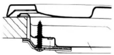
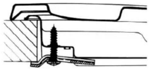
Fixing elements (hooks and screws) are included for installing the hob on a 20 to 40 mm thick worktop.
Distance required for hob installation without extractor hood (Fig. 6).
Distance required for hob installation under an extractor hood (Fig. 7).
| Model A B | ||
| Bolero Squad G 1400S InoxBolero Squad G 2400S Inox 270 480 | ||
| Bolero Squad G 3400S InoxBolero Squad G 4400S InoxBolero Squad G 5400S Inox | 560 480 |
The installation dimensions are shown in figure 8.
Note: Use the hooks included in the accessory bag as shown in figure 9.
Fig. 9 key:
A.- Hook position for a 20 mm thick worktop.
B.- Hook position for a 30 mm thick worktop.
C.- Hook position for a 40 mm thick worktop.
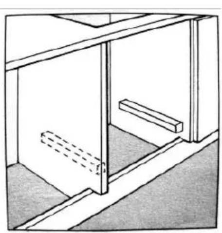
- If the gas hob is not installed above a built-in oven, a wooden board must be inserted for insulation. This board must be placed at least 20 mm from the bottom of the hob.
Important: When installing the hob on a built-in oven, the latter must be placed on two wooden slats. In case of installation on a wooden board, remember to leave at least 45 x 560 mm of space between the board and the rear (Fig. 10).
When installing the hob above a built-in oven without ventilation, ensure there are air inlets and outlets to properly ventilate the inside of the cabinet (Fig. 11).
Gas connection
The hob must be connected to the gas supply by a qualified technician. During installation, it is essential to install an approved gas valve to isolate the supply to the hob and make its subsequent removal or maintenance easier. The connection of the hob to the gas or LPG network must be carried out in accordance with current regulations and only after checking that it can be adapted to the gas type to be used. If not, follow the instructions in the “Adaptation to different gas types” section. In case of LPG-tank connection, use pressure regulators in accordance with current regulations.
Note: For proper gas regulation and longer hob service life, ensure that gas pressure matches the values indicated in table 1 "Burner and injector specifications".
Connection with a rigid pipe (copper or steel)
- The connection to the gas supply must be made so that no stress points are created on any part of the gas hob.
- The hob is equipped with an elbow joint and gas supply gasket.
- Remove the elbow joint and replace the gasket.
- Use a 1/2" threaded elbow joint to connect the gas hob to the cylinder.
Connection with a flexible metal tube
- Use a 1/2" threaded elbow joint to connect the gas hob to the tube. Only use tubes and sealing joints that comply with current regulations. The maximum length of flexible tubes must not exceed 2000 mm. Once connected, make sure the flexible metal tube does not touch any moving parts and is not crushed.
Leakage test
- Once the hob has been installed, check the gas connections for leaks using soapy water (never use fire).
Electric connection
The gas hob is equipped with a three-pole power cable designed for use with alternating current, in accordance with the specifications on the rating plate located under the hob. The earth wire is yellow and green.
For installation above a built-in oven, the electrical connections for the hob and oven must be independent, not only for safety but also for convenience when removing them in the future.
Gas hob electrical connection
Connect the power cable to a standard socket compatible with the power indicated on the rating plate or connect it directly to the mains. In the latter case, a single-pole switch must be
ENGLISH
installed between the gas hob and the mains, with a minimum contact separation of 3 mm. Do this in accordance with current safety regulations (the switch must not interrupt the earth line). The power cable must be positioned so that it never reaches a temperature higher than 50 °C above room temperature.
Before making the connection, make sure that:
- The fuse and power supply can withstand the power required by the gas hob.
- The electrical supply system has an earth connection that complies with current regulations.
- The plug or switch is easily accessible.
The main cable wires are colour-coded as follows:
Green/Yellow = Earth
Blue = Neutral
Brown = Phase
If the wire colours do not match your plug terminals:
- Connect the green/yellow wire to "E", or green or green and yellow terminal.
- Connect the brown wire to "L" or red terminal.
- Connect the blue wire to "N" or black terminal.
4. OPERATION
The position of the corresponding gas burner is indicated on each control knob.
Gas burners
- The burners have different sizes and power settings.
- Choose the most suitable one according to the diameter of the cookware being used.
- Burner power can be adjusted by turning the corresponding control knob using one of the following settings:
| Off |  |
| Maximum power | [0x7z][7762] |
| Minimum power |  |
For models with thermocouple safety system
Press and turn the knob to ignite the burner. Press and hold firmly for about 6 seconds after the flame has ignited.
For models with ignition spark plug
First press the electronic ignition button, identified with the symbol , and then press the corresponding knob and turn it counterclockwise to the "Maximum power" position.
Igniting a burner
Press the corresponding knob and turn it counterclockwise to the "Maximum power" position. Press and hold until sparks appear, and the burner flame ignites.
Warning: If the flame is accidentally extinguished during operation, turn off the gas supply with the knob and wait at least one minute before reigniting the burner.
Switching off a burner
Turn the corresponding knob clockwise to the "Off" position.
Suitable cookware
To save energy and prevent damage, please follow the instructions below:
- Use cookware with an appropriate size for each burner (see attached table). Make sure that the flame does not touch the sides of the container.
- Use flat-bottomed cookware and always cook with the lid on.
- The recommended cooking settings (maximum, medium or minimum power) will depend on use and food type, as well as the material of the containers used.
| Burner 0 Cookware diameter (cm) | |
| Auxiliary burner 10-14 | |
| Semi-rapid burner 16-20 | |
| Rapid burner 22-24 | |
| Triple-crown wok burner 24-26 |
ENGLISH
Table 1: Burner and injector specifications
Adapting the gas hob according to the gas type
| G20 natural gas G30 butane gas | G31 propane gas | |||||
| Burner Heat input (kW) | Injector 1/100 (mm) | Heat input (kW) | Injector 1/100 (mm) | Heat input (kW) | Injector 1/100 (mm) | |
| Auxiliary | 171152152 | |||||
| Semi-rapid | 1.80971.867 | 1.867 | ||||
| Rapid | 2.401102.40 | 772.4077 | ||||
| Triple-crown wok | 3.401253.40 | 933.4093 | ||||
| Supply pressure | 20 mbar | 30 mbar | 37 mbar | |||
| P.C.I.G20 | 37.78 MJ/m3 | P.C.I.G25.1 | 32.51 MJ/m3 |
| P.C.I.G25 | 32.49 MJ/m3 | P.C.I.G27 | 30.98 MJ/m3 |
| P.C.I.G2.350 | 27.20 MJ/ m3 | P.C.I.G30 | 49.47 MJ/kg |
At 15 °C and 1013 mbar - dry gas
Replacing the burner injector: unscrew the injector with a suitable tool (not included).
Fit the new injector to the burner according to the type of gas used (see table 1). Fig. 12
Note: After adapting the hob connection to another gas type, make sure to attach a label with this information to the hob.
Table 2: Changing the gas type
Gas glow regulation through valve
| Burner Flame | Switching from | LPG to natural gas | Switching from natural gas to LPG |
| Burners | High flame Replace the burner injector following the instructions in table 1. | Replace the burner injector following the instructions in table 1. | |
| Short flame Turn the adjustment screw (Fig. 13) to regulate the flame. | Turn the adjustment screw (Fig. 13) to regulate the flame. | ||
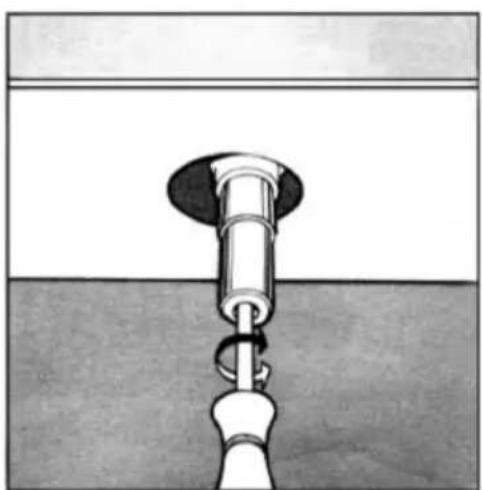
Valve and gas flow rate adjustment
To adjust the gas valve and regulate the flame, first turn the control knob to the "Minimum power" position.
Remove the knob and adjust the flame with a small screwdriver. (Fig. 13)
To check if the flame has reached the desired intensity, ignite the burner at "Maximum power" position for 10 minutes. Then turn the knob to the "Minimum power" position. The flame should not extinguish or move towards the injector. If this occurs, readjust the gas valve.
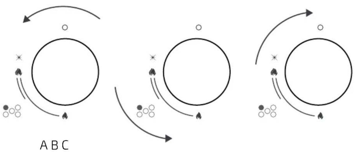
Flame settings
If combustion is occurring efficiently, the flame colour should be deep blue on the outside and slightly lighter on the inside. The flame size depends on the position of the corresponding knob.
See figure 14 for the different operating settings (flame size selection). When starting cooking, turn the knob to the "Maximum power" position to activate the high flame. This will heat the container more quickly. Then turn the knob to the "Minimum power" position to activate the short flame and maintain cooking. It is recommended to adjust the flame size progressively.
Fig. 14 key:
A.- High flame (maximum power).
B.- Short flame (minimum power).
C.- Off.
It is forbidden to adjust the flame between the "Off" and "Maximum power" positions.
Please note the following energy saving tips:
- Use the hob correctly.
- Choose the appropriate burner for the container size.
ENGLISH
- Use suitable cookware.
- Up to 60% energy savings when using appropriate cookware.
- Up to 60% energy savings when the hob is used correctly, and appropriate flame size is selected.
- For efficient hob operation and lower energy consumption, it is essential to keep the burners clean (especially the flame outlet holes and injectors).
Table 3: Adaptation to different gas types
Appliance category: I_2E I_2E+ I_2L I_2HS I_2ELS I_2ELW I_3+ I_3B/P I_3B/P I_3B/P I_3P I_2H3+ II_2E3B/P II_2HS3B/P II_2ELWLS3B/P II_2ELL_3B/
| Burner Gas type | Supply pressure Injector diameter | ||
| mbar | 1/100 mm | ||
| Auxiliary | G20 natural gas 20 | 71 | |
| G30 butane gas | 30 | 52 | |
| 37 | 47 | ||
| G37 propane gas | 50 | 45 | |
| Semi-rapid | G20 natural gas 20 | 97 | |
| G30 butane gas | 30 | 67 | |
| 37 | 64 | ||
| G37 propane gas | 50 | 59 | |
| Rapid | G20 natural gas 20 | 110 | |
| G30 butane gas | 30 | 77 | |
| 37 | 73 | ||
| G37 propane gas | 50 | 67 | |
| Triple-crown wok | G20 natural gas | 20 | 125 |
| G30 butane gas | 30 | 93 | |
| 37 | 88 | ||
| G37 propane gas | 50 | 82 | |
Table 4: Gas source and country classification
| Rated heat input Reduced heat input | ||||||
| — | 95 | 1 | 860 | 0.40 | 344 | |
| 72.6 | — | 1 | 860 | 0.40 | 344 | |
| 72.6 | — | 1 | 860 | 0.40 | 344 | |
| 72.6 | — | 1 | 860 | 0.40 | 344 | |
| — | 171 | 1.8 | 1548 | 0.60 | 516 | |
| 130.8 | — | 1.8 | 1548 | 0.60 | 516 | |
| 130.8 | — | 1.8 | 1548 | 0.60 | 516 | |
| 130.8 | — | 1.8 | 1548 | 0.60 | 516 | |
| — | 228 | 2.4 | 2064 | 0.90 | 774 | |
| 174 | — | 2.4 | 2064 | 0.90 | 774 | |
| 174 | — | 2.4 | 2064 | 0.90 | 774 | |
| 174 | — | 2.4 | 2064 | 0.90 | 774 | |
| — | 323 | 3.4 | 2924 | 1.50 | 1090 | |
| 247 | — | 3.4 | 2924 | 1.50 | 1090 | |
| 247 | — | 3.4 | 2924 | 1.50 | 1090 | |
| 247 | — | 3.4 | 2924 | 1.50 | 1090 | |
ENGLISH
| Gas category Supply | pressure Country | |
| I2H G20 20 mbar AT, | BG, CZ, DK, EE, FI, GR, HR, HU, IS, | IE, IT, LV, LT, NO, PT, RO, SK, SI, ES, SE, CH, TR, GB |
| I2E G20 20 mbar DE, | LU | |
| I2E+ G20/G25 20/25 | mbar BE, FR | |
| I2L G25 25 mbar NL | ||
| I2HS G20/G25.1 25 m | bar HU | |
| I2ELS G20 20 mbar, | G2.350 13 mbar PL | |
| I2ELW | G20/G27 20 mbar | PL |
| I3+ | G30-G31 (28-30)-37 mbar | BE, CY, CZ, EE, FR, GR, IE, IT, LT, LU, LV, PT, RO, SK, ES, CH, GB |
| I3B/P | G30 30 mbar | BE, CY, CZ, DK, EE, FI, GR, HR, LV, LT, LU, MT, NL, NO, SK, SI, SE, TR |
| I3B/P | G30 37 mbar | PL |
| I3B/P | G30 50 mbar | AT, DE, HU, CH |
| I3P G31 37 mbar | CH, FR, GR, IE, ES, | GB |
| I2H3+ | G20 20 mbarG30-G31 (28-30)-37 mbar | GR, IE, IT, PT, ES, GB, CH, CZ, SI, SK |
| II2E3B/P | G20 20 mbar, G30 30 mbar | RO |
| II2HS3B/P | G20/G25.1 25 mbarG30 30 mbar | HU |
| II2ELWLS3B/P | G20/G27 20 mbarG2.350 13 mbar, G30 37 mbar | PL |
| II2ELL3B/P | G20 20 mbar, G25 25 mbarG30 50 mbar | DE |
This gas hob complies with the following European Union directives:
- 73/23/EEC of 19/02/73 (Low Voltage Directive concerning electrical equipment designed for use within certain voltage limits) and subsequent amendments.
- 89/336/EEC of 03/05/89 (Electromagnetic Compatibility) and subsequent amendments.
- 90/396/EEC of 29/06/90 (Gas Appliances) and subsequent amendments.
- 93/68/EEC of 22/07/93 and subsequent amendments.
5. CLEANING AND MAINTENANCE
Before carrying out any cleaning or maintenance tasks, disconnect the gas hob from the mains. To extend the service life of the gas hob, it is essential to clean it regularly. When doing so, keep the following in mind:
- The enamelled parts and glass surface (only on certain models) should be cleaned with warm water. Avoid using abrasive cleaning products or corrosive substances that could damage the enamel or scratch the glass.
- The removable burner components should be washed with warm water and mild soap after each use. Make sure to remove any encrusted food residues.
- The automatic ignition spark plug should be cleaned periodically with a non-metallic brush. After cleaning, ensure that ignition occurs normally.
- Stainless steel surfaces and other iron parts can be damaged by contact with water containing high concentrations of limescale or corrosive cleaning products (containing phosphorus). To extend their useful life, it is recommended to rinse them with warm water and dry them thoroughly to remove any drops or other liquids.
- After each use, clean the hob surface with a damp cloth to remove dust or food residues. The glass surface (only on certain models) should be cleaned regularly with warm water and non-corrosive cleaning products.
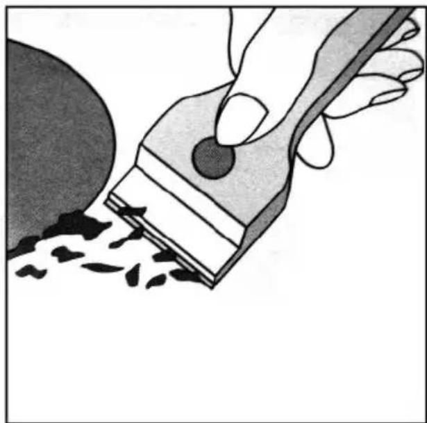
- First, remove any food or grease residues with a glass ceramic scraper (not included). (Fig. 15).
Warning: Extreme caution, RISK OF CUTS.
- Take advantage while the surface is still warm to clean it with a suitable cleaning product and paper towel. Then wipe it with a damp cloth and dry it thoroughly.
Warning: Extreme caution, RISK OF BURNS.
- Remove any aluminium foil or plastic residues and immediately remove any melted sugar or spilled foods with high sugar content from the surface.
- Do not use steel scouring pads or harsh or abrasive cleaning products, such as spray cleaners.
- Allow the pan supports to cool down slightly. Carefully remove the pan supports from the gas hob. Place them in the sink and remove food or grease residues with a non-metallic brush and soapy water. Rinse the pan supports with water and dry them thoroughly before putting them back in place.
Warning: Extreme caution, RISK OF BURNS.
Cleaning the gas valves
Over time, it is common for gas valves to become blocked due to the accumulation of dirt (burnt grease, food residues, liquids, etc.), which can prevent gas from flowing. To prevent this from happening, clean the burner holes and the inside of the gas valves with a degreasing product.
ENGLISH
Note: This procedure must only be carried out by a qualified technician.
6. TROUBLESHOOTING
In some cases, the faults detected can be easily solved. Before contacting the Technical Support Service, check that the gas and electricity supplies have not been cut off.
The burner does not ignite, or the flame is uneven.
Check that:
- The burner outlet holes are not obstructed.
- All parts of the burners are correctly positioned.
- There are no draughts around the burner.
The flame is extinguished when the knob is released.
Check that:
- You have pressed the control knob firmly.
- You have kept the control knob pressed for long enough. This will activate the thermocouple gas flow system.
- The thermocouple safety system hole is not obstructed.
The flame is extinguished when turning the knob to the "Minimum power" position.
Check that:
- The burner outlet holes are not obstructed.
- There are no draughts around the burner.
- You have correctly turned the knob to the "Minimum power" position.
The cookware is unstable on the hob.
Check that:
- The cookware is not deformed, and its base is completely flat.
- The cookware is properly centred on the burner.
- The pan support is properly positioned (not inverted).
If after checking the above, the gas hob still does not work properly, please contact the official Cecotec Technical Support Service.
7. TECHNICAL SPECIFICATIONS
Product reference:
EU01_100478
EU01_100482
EU01_100486
EU01_100490
EU01_100494
Product:
Bolero Squad G 1400S Inox Gas Hob
Bolero Squad G 2400S Inox Gas Hob
Bolero Squad G 3400S Inox Gas Hob
Bolero Squad G 4400S Inox Gas Hob
Bolero Squad G 5400S Inox Gas Hob
ERP tables
| Product type | Built-in gas hob |  PIN CODE: 2575DN33174 PIN CODE: 2575DN33174 |
| Class | Class 3 | |
| Manufacturer | CECOTEC INNOVACIONES, S.L.Av. Reyes Católicos, 60,46910, Alfafar (Valencia) - SPAIN | |
| Voltage/Frequency(Rated) | 220-240 V AC, 50/60 Hz | |
| Reference EU01_100478 | ||||
| Gas type G20 20 mbar | ||||
| Burner type Wok Rapid Semi-rapid Auxiliary | ||||
| EE burner 57.05% -- NA | ||||
| EE gas hob 57.05% | ||||
ENGLISH
| Reference EU01_100482 | ||||
| Gas type G20 20 mbar | ||||
| Burner type Wok Rapid Semi- | rapid 1 Auxiliary | |||
| EE burner 57.05% - 57.61% NA | ||||
| EE gas hob 57.33% | ||||
| Reference EU01_100486 | ||||
| Gas type G20 20 mbar | ||||
| Burner type Wok Rapid Semi- | rapid 1 Auxiliary | |||
| EE burner 57.05% - 57.61% NA | ||||
| EE gas hob 57.33% | ||||
| Reference EU01_100490 | ||||
| Gas type G20 20 mbar | ||||
| Burner type Wok Rapid Semi- | rapid 1 Auxiliary | |||
| EE burner 57.05% - 2 x 57.61% NA | ||||
| EE gas hob 57.42% | ||||
| Reference EU01_100494 | ||||
| Gas type G20 20 mbar | ||||
| Burner type Wok Rapid Semi- | rapid 1 Auxiliary | |||
| EE burner 57.05% 54.74% 2 x 57.61% NA | ||||
| EE gas hob 56.75% | ||||
The hobs are configured to operate with natural gas and the Energy Efficiency calculations have been performed with this gas. If modification for LPG (butane/propane) is carried out, the
Energy Evidence values may be modified.
Technical specifications may change without prior notice to improve product quality.
Made in China | Designed in Spain
8. DISPOSAL OF OLD ELECTRICAL AND ELECTRONIC APPLIANCES
This symbol indicates that, according to the applicable regulations, the product and/or batteries must be disposed of separately from household waste. When this product reaches the end of its shelf life, you should dispose of the cells/batteries/accumulators and take them to a collection point designated by the local authorities.
For detailed information on how to properly dispose of electrical and electronic appliances and/or batteries, consumers should contact their local authorities.
Compliance with the above guidelines will help protecting the environment.
9. TECHNICAL SUPPORT AND WARRANTY
Cecotec shall be liable to the end user or consumer for any lack of conformity that exists at the time of product delivery under the terms, conditions and deadlines established by applicable regulations.
Repairs should be carried out by qualified personnel.
If at any moment you detect any problem with your product or have any doubt, do not hesitate to contact the official Cecotec Technical Support Service at +34 96 321 07 28.
10. COPYRIGHT
The intellectual property rights over the texts in this manual belong to CECOTEC INNOVACIONES, S.L. All rights reserved. The contents of this publication may not, in whole or in part, be reproduced, stored in a retrieval system, transmitted, or distributed by any means (electronic, mechanical, photocopying, recording or similar) without the prior authorization of CECOTEC INNOVACIONES, S.L.
11. DECLARATION OF CONFORMITY
cecòtec
Document identification number: CECODOC002170 v.00
Manufacturer: CECOTEC INNOVACIONES S.L
Address: Av. Reyes Católicos No. 60-46910, Alfajar (Valencia), Spain
This declaration of conformity is issued under the sole responsibility of the manufacturer.
Object of the declaration:
Brand: CECOTEC
Appliance description: Gas hobs
Appliance reference: A01_EU01_100478, A01_EU01_100479, A01_EU01_100480, A01_EU01_100481, A01_EU01_100482, A01_EU01_100483, A01_EU01_100484, A01_EU01_100485, A01_EU01_100486, A01_EU01_100487, A01_EU01_100488, A01_EU01_100489, A01_EU01_100490, A01_EU01_100491, A01_EU01_100492, A01_EU01_100493, A01_EU01_100494, A01_EU01_100495, A01_EU01_100496, A01_EU01_100497.
Appliance category: I_2H , I_2E(20) , I_2E+(20) , I_3+(28-30/37) , I_3B/P(30) , I_3B/P(37) , I_3B/P(50) , I_3P/P(37) , I_2EK , I_2ELS , I_2ELW
Gas pressure (mbar): 20 mbar, (20/25) mbar, (28-30) mbar, (28-30/37) mbar, 37 mbar, 50 mbar, 25 mbar, 13 mbar.
The object of the declaration described above is in conformity with the relevant Union harmonisation legislation:

2016/426/EU

2011/65/EU and its amendments

2014/35/EU

66/2014/EU and its amendments

2014/30/EU and its amendments
References of the relevant harmonised standards used:

EN 30-1-1:2021+A1:2023, EN 30-2-1:2015

EN 60335-1:2012 + A11:2014 + A13:2017 + A1:2019 + A14:2019 + A2:2019 + A15:2021

EN 60335-2-102:2016

EN 62233:2008

EN IEC 55014-1:2021

EN IEC 61000-3-2:2019 +A1:2021

EN IEC 55014-2:2021

EN 61000-3-3:2013 +A1:2019 +A2:2021
The notified body number 2575, Intertek Italia SpA with address: Via Miglioli, 2/A - 20063 Cernusco sul Naviglio, Milano - Italy, has carried out the conformity assessment according to MODULE B: EU-type examination - production type and issued certificate number S-2575-GAR-2233174-R3 dated 24-01-2024 and remains valid until 11-05-2028 unless suspended or withdrawn, and according to MODULE D: Conformity to type based on quality assurance of the production process, and has issued the following certificate:
The undersigned is responsible for compiling the technical file and makes this declaration on behalf of CECOTEC INNOVACIONES S.L.
Signed for and on behalf of:
Alfafar (Valencia), Spain, 27/01/2025
Signed by: José Orts
Position: C.B.O

natural_image
Abstract line drawing with intersecting lines and a small blue highlight (no text or symbols)1. PIÈCES ET COMPOSANTS
Img. 1
Important : Faites attention, RISOUE DE COUPURES.
natural_image
Abstract blue line drawing with intersecting strokes (no text or symbols)DEUTSCH
1. TEILE UND KOMPONENTEN
Abb. 1
natural_image
Abstract line drawing with intersecting curved lines (no text or symbols)ITALIANO
1. PARTI E COMPONENTI
Fig. 1
natural_image
Abstract blue line drawing with intersecting strokes (no text or symbols)PORTUGUÊS
1. PEÇAS E COMPONENTES
Fig. 1
natural_image
Abstract line drawing with intersecting blue lines on white background (no text or symbols)NEDERLANDS
1. ONDERDELEN EN COMPONENTEN
Fig. 1
6. PROBLEEMOPLOSSING
natural_image
Abstract blue line drawing with intersecting strokes (no text or symbols)POLSKI
1. CZĘŚCI I KOMPONENTY
RYS.1
natural_image
Abstract blue line drawing with intersecting strokes (no text or symbols)ČEŠTINA
1. DÍLY A SOUČÁSTI
OBR.1
natural_image
Abstract blue line drawing with intersecting strokes (no text or symbols)TÜRKÇE
natural_image
Abstract line drawing with intersecting curved lines (no text or symbols)ΕΛΛΗΝΙΚΑ
1. MEPH KAI EΞAPTHMATA
EIK. 1
natural_image
Abstract blue line drawing with intersecting strokes (no text or symbols)CATALÀ
1. PECES I COMPONENTS
FIG. 1
|2EK,|2ELs,|_2ELw
Pressió de gas (mbar): 20 mbar, (20/25) mbar, (28-30) mbar, (28-30/37) mbar, 37 mbar, 50
mbar, 25 mbar, 13 mbar.
natural_image
Abstract blue line drawing with intersecting strokes (no text or symbols)MAGYAR
GYÁRTÓ: CECOTEC INNOVATIONS S.L
CÍM: Av. Reyes Católicos, 60, 46910, Alfafar, Valencia (Spanyolország)
natural_image
Abstract blue line drawing with intersecting strokes (no text or symbols)- نیت
natural_image
Abstract blue line drawing with intersecting curves and a central teal shape (no text or symbols)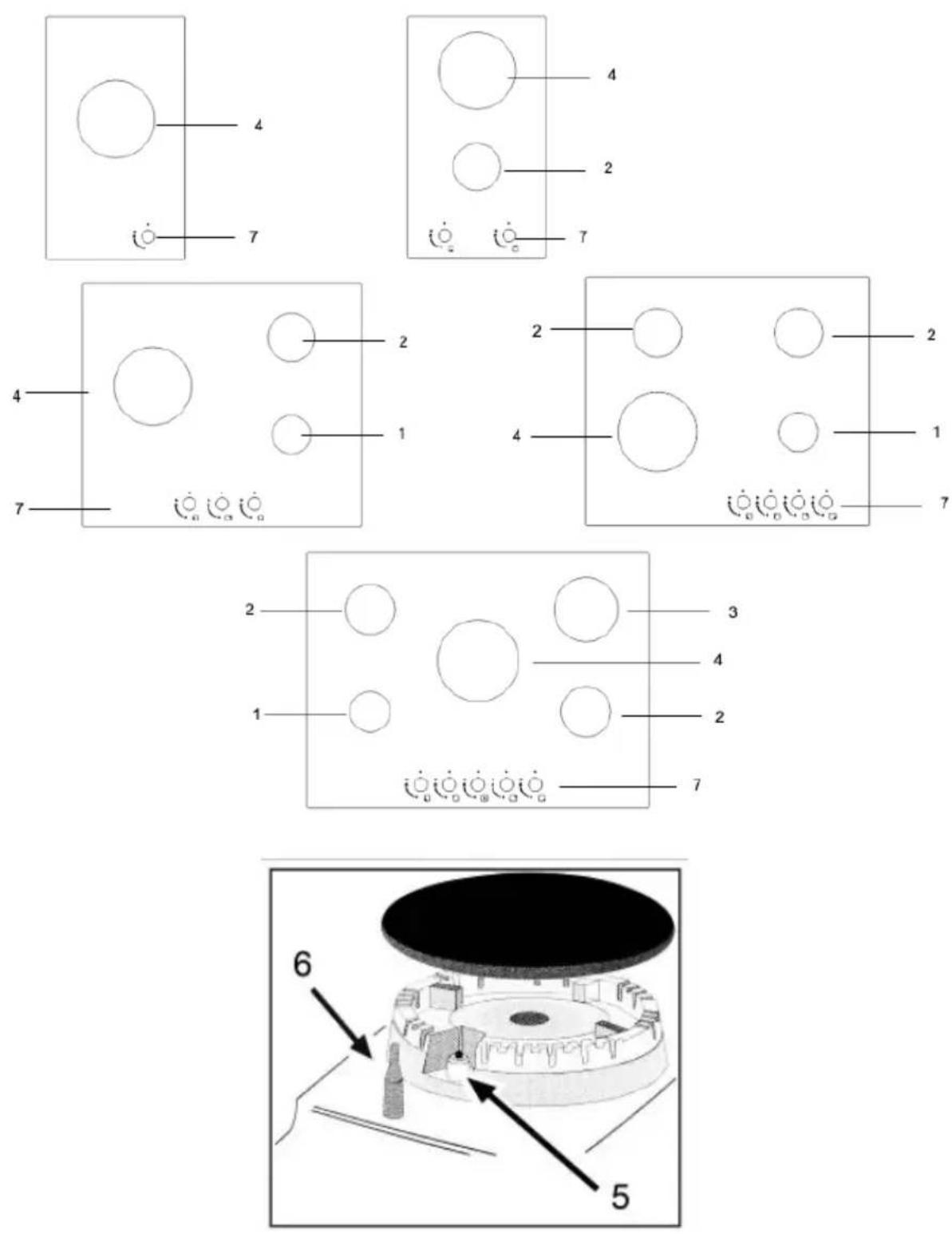
Fig./Img./Abb./Afb./Rys.1
natural_image
Simple line drawing of a house with a stove and airflow indicators (no text or symbols)Fig./Img./Abb./Afb./Rys.2
natural_image
Technical line drawing of a door with a side-mounted vertical structure and a magnified inset showing internal components (no text or symbols)Fig./Img./Abb./Afb./Rys. 3
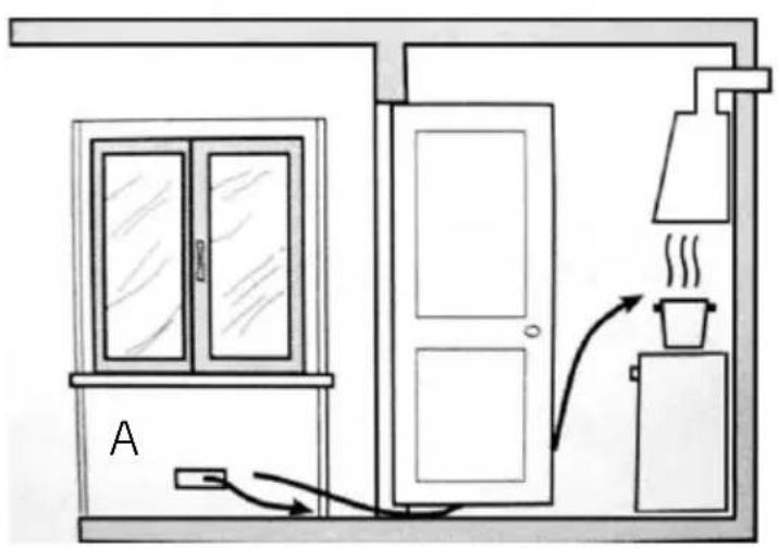
Fig./Img./Abb./Afb./Rys. 4
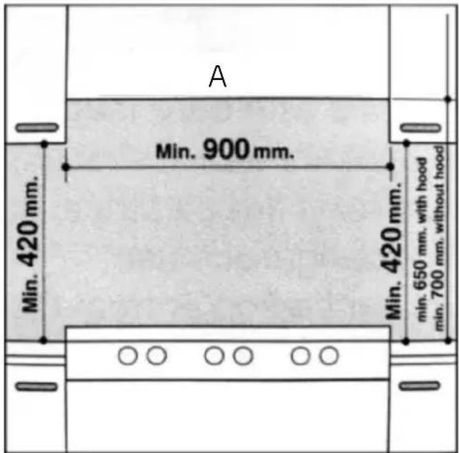
Fig./Img./Abb./Afb./Rys.5
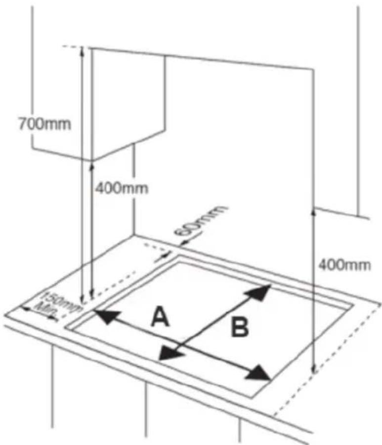
Fig./Img./Abb./Afb./Rys. 6
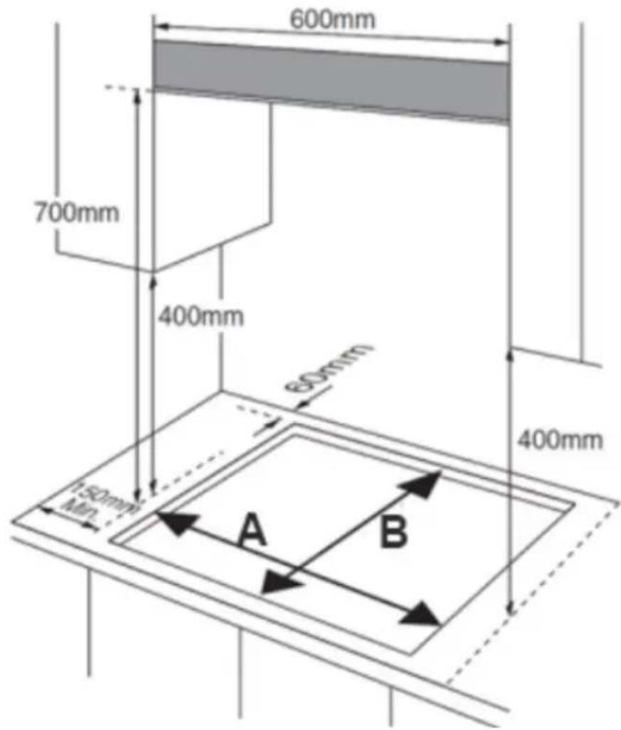
Fig./Img./Abb./Afb./Rys.7
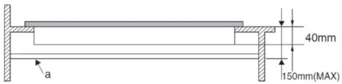
Fig./Img./Abb./Afb./Rys. 8
natural_image
Technical cross-sectional diagram of a mechanical assembly (no text or labels)A B C
natural_image
Technical cross-section diagram of a mechanical assembly (no text or labels)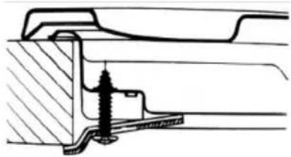
natural_image
Cross-sectional technical drawing of a mechanical assembly (no text or symbols visible)Fig./Img./Abb./Afb./Rys.9
natural_image
Isometric line drawing of a two-story cabinet or enclosure with windows and doors, showing structural details (no text or symbols)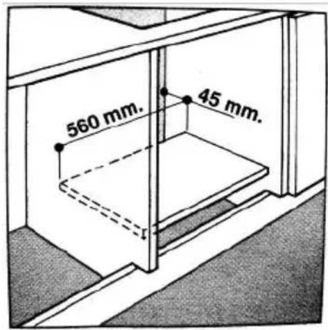
Fig./Img./Abb./Afb./Rys.10
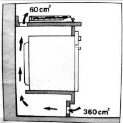
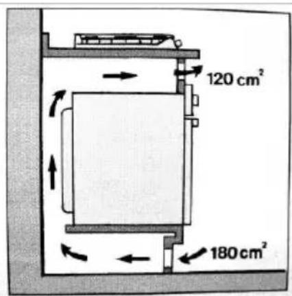
Fig./Img./Abb./Afb./Rys. 11

natural_image
Top-down schematic of a circular mechanical component with a central hub and an arrow pointing to it (no text or symbols)Fig./Img./Abb./Afb./Rys.12
natural_image
Diagram of a mechanical assembly with a central shaft and base, no text or symbols present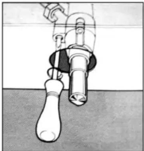
natural_image
Mechanical device with lever and handle assembly (no visible text or symbols)Fig./Img./Abb./Afb./Rys.13
flowchart
graph TD
    A["Circle with circles"] --> B["Process 1: Arrow to circle"]
    B --> C["Process 2: Arrow to circle"]
    C --> D["Process 3: Arrow to circle"]
    style A fill:#fff,stroke:#000
    style B fill:#fff,stroke:#000
    style C fill:#fff,stroke:#000
    style D fill:#fff,stroke:#000
Fig./Img./Abb./Afb./Rys.14
natural_image
Illustration of a hand using a tool to brush or brush over a surface, with no visible text or symbols.Fig./Img./Abb./Afb./Rys.15
www.cecotec.es