
AST300PPM - Measuring equipment INFICON - Free user manual and instructions
Find the device manual for free AST300PPM INFICON in PDF.

| Brand | INFICON |
| Model | AST300PPM |
| Category | Measurement equipment |
| Product type | Refrigerant gas leak detector with PPM display |
| Sensor type | Infrared |
| Compatible refrigerants | All CFCs, HCFCs, HFCs, HFOs, blends (including A2L); optional CO₂ sensor (R744) |
| Minimum sensitivity (Directional mode, Super) | 1 g/year |
| Resolution (Cloud Hunting mode) | 1 ppm |
| Display range (Cloud Hunting mode) | 0 to 9,999 ppm |
| Accuracy (Cloud Hunting mode, clean air, R134a) | ±1 ppm ±10 % of reading |
| Power supply | Rechargeable lithium-ion battery, input 5 V (DC) ±5 %, 1 A ±5 % |
| Charging connector | Micro USB |
| Charging time (0 to 100 %) | Approximately 3 hours |
| Battery life | Approximately 8 h (Cloud Hunting), approximately 10 h (Pinpoint) |
| Weight (with battery, without accessories) | 0.50 kg (1.10 lb) |
| Operating temperature | -20 to 50 °C (-4 to 122 °F) |
| Operating humidity | 95 % RH max, non-condensing |
| Warm-up time | 45 to 90 seconds (Manual Zero mode: up to 15 min) |
| Detection modes | Cloud Hunting (PPM monitor), Directional (auto-zero), Manual Zero |
| Cleaning and maintenance | Clean with mild detergent or isopropyl alcohol; replace hydrophobic filter if clogged |
| Main spare parts | Standard sensor (724-701-G1), CO₂ sensor (724-701-G2), battery (721-702-G1), filter (712-707-G1), extra-long probe (721-611-G1) |
| Safety | Do not use in explosive atmosphere; exposure to CO₂ or refrigerants is hazardous; do not block exhaust |
| Warranty | 1 to 2 years depending on region (excluding batteries, sensors, filters) |
| Included accessories (examples) | Wall charger, car charger, earphones, extra-long probe, spare filter |
Frequently Asked Questions - AST300PPM INFICON
User questions about AST300PPM INFICON
0 question about this device. Answer the ones you know or ask your own.
Ask a new question about this device
Download the instructions for your Measuring equipment in PDF format for free! Find your manual AST300PPM - INFICON and take your electronic device back in hand. On this page are published all the documents necessary for the use of your device. AST300PPM by INFICON.
USER MANUAL AST300PPM INFICON
Operating Manual
AST300PPM
Refrigerant Leak Detector with PPM Display
English · Español · Deutsch · Français · Italiano · 中文 · 日本語 · Русский
1 Declaration of Conformity
INFICON
EU DECLARATION OF CONFORMITY
This declaration is issued under the sole responsibility of the manufacturer INFICON. The object of the declaration is to certify that this equipment, designed and manufactured by:
INFICON Inc.
Two Technology Place
East Syracuse, NY 13057
USA
is in conformity with the relevant Community harmonization legislation. It has been constructed in accordance with good engineering practice in safety matters in force in the Community and does not endanger the safety of persons, domestic animals or property when properly installed and maintained and used in applications for which it was made.
| Equipment Description: | AST300PPM Refrigerant Leak Detector with PPM Display | ||
| Model Number: | AST300PPM | (Applicable to all Group numbers) | |
| Applicable Directives: | 2014/35/EU | LVD | |
| 2014/30/EU | General EMC | ||
| 2011/65/EU | as amended by 2015/863/EU RoHS | ||
| 2006/66/EC | as amended by 2013/56/EU Battery Directive | ||
| Applicable Standards: | |||
| Safety: | EN 61010-1:2010 | Safety requirements for electrical equipment for measurement, control, and laboratory use.General requirements | |
| EN 62133:2013 | Safety requirements for portable sealed secondary cells and for batteries made from them, for use in portable applications. CB Test Cert DK-73443-UL | ||
| UL 2054 | UL Standard for Safety Household and Commercial Batteries Cert 20180518-MH29443 | ||
| UL 60950-1 & CAN/CSA-C22.2 No. 60950-1-07 | UL Standard for Safety Information Technology Equipment – Safety – Part 1: General Requirements Cert 20180518-MH294 | ||
| UN 38.3 | UN Manual of Tests and Criteria, Part III, sub-section 38.3. Safe Transport of Li-Ion Rechargeable Battery | ||
| Emissions: | EN 61326-1:2013 Edition 2.0 (Radiated, Conducted & Harmonic Emissions)(EMC- Measurement, Control & Laboratory Equipment)CISPR 11/EN 55011:2009 (+A1:2010) | Emission standard for industrial, scientific, and medical (ISM) radio RF equipment, Class A | |
| Immunity: | EN 61326-1:2013 Edition 2.0 (EMC – Measurement, Control & Laboratory Equipment) Immunity per Table A.1 – Portable Test and Measurement Equipment | ||
| RoHS | Compliant | ||
CE Implementation Date: September 23, 2020
Authorized Representative:
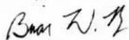
Brian King
INFICON
Business Line Manager – Service Tools
Two Technology Place
East Syracuse, NY USA 13057
EC Authorized Representative
INFICON GmbH
50968 Köln, Bonner Str. 498
2 Cautions and Warnings
Cautions:
- Only use a certified charger/cord with an output of 5 V (dc) ±5%, 1 A ±5%.
- Keep the device out of extremely high or low temperature locations.
- Do not expose the battery to liquid.
- Do not use the device if you notice any damage to the battery.
- Do not disassemble or modify the battery.
- Handle and dispose of the battery per local regulations.
- If the recharging operation fails to complete, even when the specified recharging time has elapsed, immediately stop further recharging.
- Do not leave the battery unattended while charging.
- Unplug the charger when the battery is fully charged.
- Improper use or disposal of lithium ion batteries can cause a fire.
- High RF environments may cause a false alarm.

WARNING
This symbol alerts the user to the presence of important operating and maintenance (servicing) instructions.

WARNING
Exposure to high concentrations of CO_2 or refrigerants is dangerous and can be life-threatening.
The instrument is not for use in toxic or hazardous environments. It is not a personal protection or life-saving device. Always exercise extreme caution in potentially toxic or hazardous environments.

WARNING
This product is not intrinsically safe and should not be used in the presence of explosive fumes, explosive dust, or other explosive chemicals. Use in an environment with flammable refrigerant concentration approaching the LEL could cause an explosion or fire resulting in serious injury, death, or damage to property.
3 Specifications
| Usage indoor/outdoor | |
| Sensor type infrared | |
| Compatible refrigerants | |
| • Refrigerant sensor (standard, PN 724-701-G1) | R134a, R1234yf and all HFCs, HFOs, and blends |
| • CO2 sensor (PN 724-701-G2) R744 (carbon dioxide) | |
| Minimum sensitivity (Pinpoint mode, Super sensitivity) | 0.03 oz/yr (1 g/yr)^1 |
| Display resolution (Cloud Hunting mode) 1 ppm | |
| Display range (Cloud Hunting mode) 0 to 9999 ppm | |
| Accuracy (Cloud Hunting mode, with clean air reference, R134a) | ±1 ppm ±10% of reading |
| Battery type lithium ion | |
| Charging input type micro USB | |
| Charging time (starting at 0%) approximately 3 hours | |
| Battery life approximately 8 hours (Cloud Hunting) approximately 10 hours (Pinpoint) | |
| Input voltage 5 V (dc) ±5% | |
| Input current 1 A ±5% | |
| Warm-up period 45–90 seconds | |
| Temperature ranges and humidity | |
| • Storage -20–60°C (-4–140°F) | |
| • Operating ^2 | -20–50°C (-4–122°F) |
| • Charging | 0–45°C (32–113°F) |
| • Humidity | 95% RH NC maximum |
| Altitude | 2000 m (6500 ft.) |
| Pollution degree | 2 |
| Overvoltage category | 2 |
| Weight (with battery; not including carrying case or accessories) | 1.10 lb. (0.50 kg) |
^1 To achieve optimal performance and the specified sensitivities, it is recommended to allow AST300PPM to run for 15 minutes prior to use.
^2 Use in temperatures below 0^ C ( 32^ F) should be limited. Extended warm-up time is recommended before use in low temperature environments.
SAE Applications
Specification table in accordance with EN 14624
| R134a R1234yf | ||
| Minimum sensitivity, fixed (static) 1 g/yr. 0.5 g/yr. | ||
| Maximum sensitivity, fixed (static)^3 | >50 g/yr. >50 g/yr. | |
| Minimum sensitivity, moving (dynamic) 1 g/yr. 1 g/yr. | ||
| Maximum sensitivity, moving (dynamic)^3 | >50 g/yr. >50 g/yr. | |
| Minimum response/detection time < 1 s < 1 s | ||
| Zeroing time 1–4 s 1–4 s | ||
| Recovery time for 50 g/yr exposure ^4 | 7.6 s 6.4 s | |
| Minimum sensitivity in contaminated environment | >2 g/yr. 1 g/yr. | |
| Calibration frequency Check annually with calibrated leak standard | ||
^3 The upper leak detection limit is not specified by INFICON as there is no upper limit to the size of the leak the detector is able to detect.
^4 As no 50 g/yr. leak standard was available during testing, a 32 g/yr leak standard was substituted.
SAE standards J2791 (R-134a) and J2913 (R-1234yf) specify sensitivity to the following leak sizes for the corresponding settings below. Super sensitivity is more sensitive than what is required by SAE for leak checking in a clean environment (free of background refrigerant). If leak checking in a contaminated environment (high background refrigerant), switch to Super sensitivity.
| R-134a leak rate (g/yr) R-1234yf leak rate (g/yr) Sensitivity Setting | ||
| 14 | 14 | low |
| 7 | 7 | medium |
| 4 | 4 | high |
The following table lists some common under hood chemicals and indicates whether or not they will cause a false-trigger from AST300PPM.
| Chemical | False-Trigger |
| Windshield washer solvent (methanol base) | yes |
| Ford® spot and stain remover | yes |
| Ford rust penetrant and inhibitor | yes |
| Ford gasket and trim adhesive | yes |
| Permatex® natural blue cleaner and degreaser | yes |
| Ford brake parts cleaner | yes |
| Ford spray carburetor tune-up cleaner | yes |
| Chemical False-Trigger | |
| Ford clear silicon rubber yes | |
| Motorcraft® G-05 antifreeze/coolant no | |
| Gunk® liquid wrench no | |
| Ford pumice/lotion hand cleaner no | |
| Ford Motorcraft DOT3 brake fluid no | |
| Ford silicon lubricant no | |
| Dexron® automatic transmission fluid no | |
| Mineral engine oil no |
SAE recommended leak test procedure

Always leak test with the engine off.
- Charge the system with sufficient refrigerant to have a gauge pressure of at least 340 kPa (50 psi) with the system off. At ambient temperatures below 15 °C (59 °F) leaks may not be measurable because the pressure may not be reached.
- Visually trace the entire refrigerant system, and look for signs of air conditioning lubricant leakage, damage and corrosion on all lines, hoses and components. Check each questionable area with the detector probe, as well as all fittings, hose-to-line couplings, refrigerant controls, service valves with caps in place, brazed or welded areas, and areas around attachment points and hold-downs on lines and components. If looking for an apparently larger leak, check first at the medium (7 g/year) or low (14 g/year) sensitivity setting.
- Always follow the refrigerant system around in a continuous path so that no areas of potential leaks are missed. If a leak is found, always continue to test the remainder of the system.
- Recheck the service valves with the caps removed. Blow shop air over the service valve to clear the immediate area. Check with a detector on the medium sensitivity setting (7 g/year).
- Move the detector at a rate of no more than 75 mm/s (3 in./s) and as close as possible to 9.5 mm (3/8 in.) from the surface, completely encircling each test position (switch, sensor, refrigerant tubing connection, etc.).
- Slower movement and closer approach of the probe normally improves the likelihood of finding a leak. However, detectors made to meet this standard are based on air sampling from the 9.5 mm (3/8 in) distance. A retest is advisable when a leak appears to be found at the most sensitive settings, particularly if the
probe was in a static position on a joint, or making physical contact with a joint, as it was moving. Repeat with a moving probe test at that location, taking care to maintain the small gap (9.5 mm or 3/8 in.) to confirm that the leak is of repairable size. Checking with the medium sensitivity setting (7 g/year) after finding an apparent leak with the high sensitivity setting (4 g/year) also may be helpful.
Patents (Pending)
• Application #10 2018 206 877.1
• Application #18171080.7
• Application # 10 2018 208 826.8
4 AST300PPM
5 Charging the Battery
AST300PPM uses a rechargeable lithium ion battery that comes partially charged. INFICON recommends charging the battery before its first use. Using the supplied charger or charging cradle accessory, a dead battery can be charged to 80% in approximately 2 hours and 100% in approximately 3 hours. A full charge typically lasts about 8 to 10 hours of operation, depending on the mode used and the operating temperature. An on-screen indicator displays the remaining battery percentage.

AST300PPM can be used while charging.
6 Turning On the Instrument and Preparing for Use

If the screen does not turn on, the battery is low and needs to be charged. AST300PPM can be used while charging.
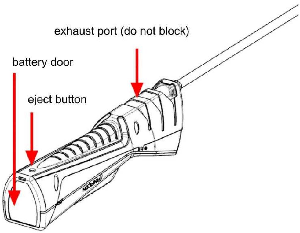
- Long press the power button (located on the left side of the body of the instrument) to turn AST300PPM On or Off.
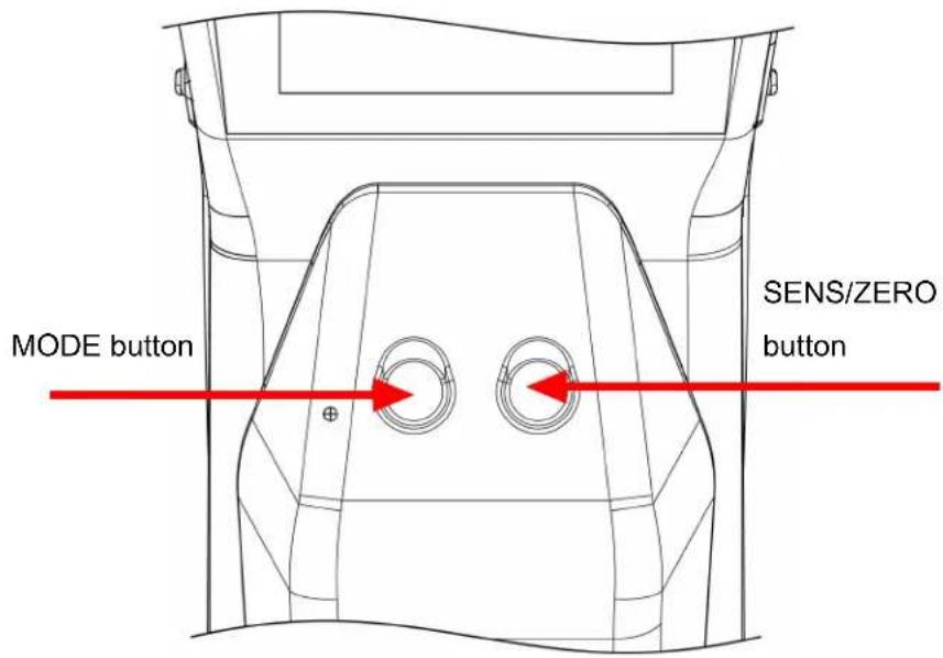
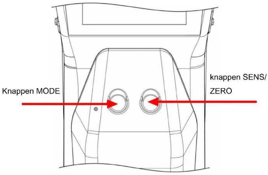
AST300PPM begins a variable-time warm-up for 45 to 90 seconds. When warm-up is complete, AST300PPM is ready to use. - To switch modes, press the MODE button. This toggles between Cloud Hunting, Pinpoint and Manual Zero modes.

AST300PPM always starts in the last mode that was used.

WARNING
Do not block the exhaust port.
Blocking exhaust air can cause false alarms or readings.
7 Screen Layout and Symbols
AST300PPM uses the display screen for all indicators and information. The display consists of a top bar, main display, and a bottom bar.
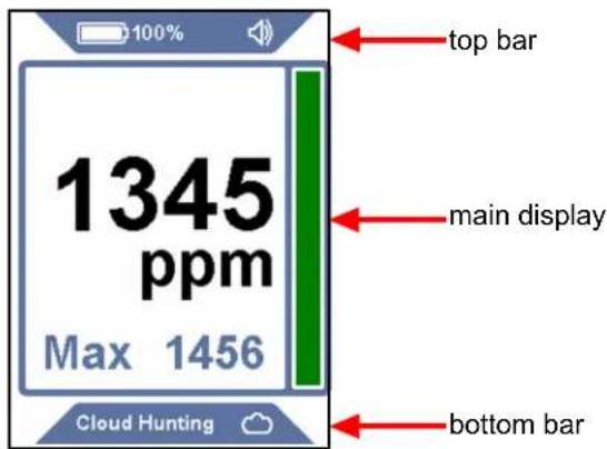
Top bar: The top bar includes the battery symbol, the percentage, the sensor indicator (when a non-standard sensor type is used), and the sound indicator.
| Symbol | Description |
| battery charge is 75-100% | |
| battery charge is 50-74% | |
| battery charge is 30-49% | |
| battery charge is 10-29% | |
| battery charge is <10% | |
| battery is charging | |
| volume is set to 100% (default) | |
| volume is set to 50% | |
| volume is muted | |
| CO2 | CO₂ sensor is installed |
Main display: The main display shows the information needed for leak checking. The main display includes the ppm reading for Cloud Hunting mode and leak indicators for Pinpoint and Manual Zero modes.
Bottom bar: The bottom bar displays the current mode and the mode indicator symbol. It also includes the sensitivity for Pinpoint mode.
Symbol Description

indicates Cloud Hunting mode

indicates Pinpoint mode

indicates Manual Zero mode

sensitivity = Super (only displayed in Pinpoint mode)

sensitivity = High (only displayed in Pinpoint mode)

sensitivity = Medium (only displayed in Pinpoint mode)

sensitivity = Low (only displayed in Pinpoint mode)
8 Cloud Hunting (Portable Monitor) Mode
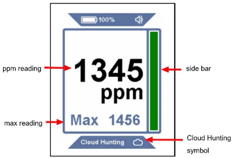
Cloud Hunting mode is identified by a large ppm reading on the display and the words Cloud Hunting on the bottom, along with a cloud symbol. The side bar increases and decreases with changes in the ppm reading.

There is no sensitivity setting in Cloud Hunting mode.
- Slowly move through the suspect areas and observe the ppm reading.
- Follow the ppm reading to find areas of higher refrigerant concentration. The higher the number, the higher the concentration.
- Press the SENS/ZERO button to enable and disable the MAX feature. When enabled, the highest ppm level observed is shown below the main ppm display. To reset the MAX reading, long-press the SENS/ZERO button or toggle the feature off and back on again.

AST300PPM uses a patent-pending switching valve in Cloud Hunting mode to constantly compare the sample from the tip of the probe with the air inside the body of the leak detector (the reference sample). This technology is what allows AST300PPM to work without the use of a carbon filter. Lingering for several minutes in an area with a high concentration of refrigerant may cause the reference sample to become
contaminated with refrigerant, which causes the ppm reading to settle back toward zero. If this occurs, move back to an area with clean air (while in Cloud Hunting mode) for a few minutes to allow the reference sample to become clean again.
9 Pinpoint Mode
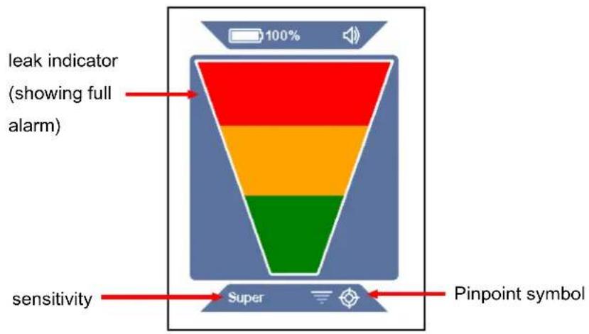
Pinpoint mode is identified by a large leak indicator on the display and a Pinpoint symbol on the bottom bar. The current sensitivity is also indicated on the bottom bar. This mode works like a standard leak detector with auto-zeroing, where the indicator bars illuminate to indicate when a leak is detected.
- Place the tip of AST300PPM as close as possible to the suspected leak (do not block the air flow).
- Slowly move the probe past each possible leak point.
If a leak is detected, AST300PPM alarms and the on-screen indicator illuminates. - When a leak is identified, pull the probe away from the leak for a few seconds and then recheck the spot to verify the leak.

In Pinpoint mode, AST300PPM automatically zeros to the background refrigerant and only alarms again with a higher concentration of refrigerant. When this occurs, either continue looking for a higher concentration of refrigerant or move the probe to an area of lower concentration for a few seconds to reset the zero point.

Press the SENS/ZERO button to switch the sensitivity setting. When working with a large leak, it can be easier to pinpoint the leak location using a lower sensitivity setting. The current sensitivity is displayed on the bottom bar.
10 Manual Zero Mode
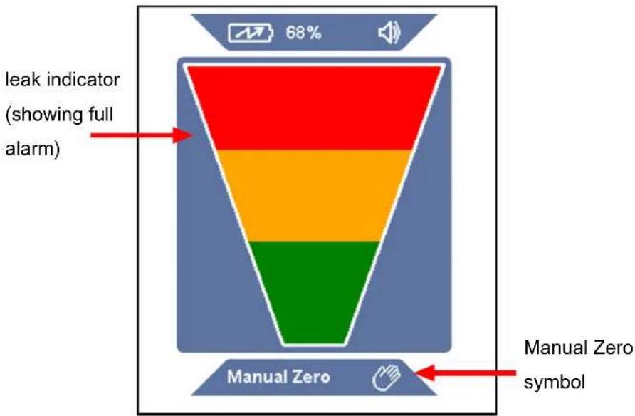
funnel
| Level | Description | |-------|-------------| | Top | leak indicator (showing full alarm) | | Bottom | Manual Zero symbol |Manual Zero mode looks and operates similar to Pinpoint mode, but is identified by the text Manual Zero and the Manual Zero symbol on the bottom bar. Manual Zero mode allows the user to manually zero to the background refrigerant by pressing the SENS/ZERO button. Once the new zero point is set, AST300PPM will not alarm unless a higher concentration of refrigerant is detected.
Manual Zero mode beeps faster at the zero point than other modes. If the concentration is lower than the current zero point, the beeping slows. This allows the user to know if they are moving away from the leak by listening to a change in the beep rate.

There is no sensitivity setting in Manual Zero mode.

Manual Zero mode requires an extra warm-up time of up to 15 minutes for optimal performance.
11 UV Inspection Light
The UV inspection light emits a beam of light approximately 400 nm in wavelength, which illuminates the fluorescent dye that is commonly installed in automotive AC systems at the factory. Use the UV inspection light to quickly check an area for leaks in a system known to contain dye, or to verify a leak after locating the leak source with your leak detector. INFICON recommends using multiple leak detection methods to verify a leak.

WARNING
Do not point UV light at people or animals.
UV light can cause damage to the eyes or blindness.
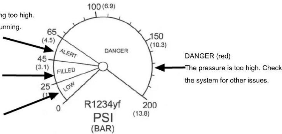
12 R1234yf Check Gauge
The R1234yf check gauge can be used to quickly check the low-side operating pressure of any R1234yf vehicle air conditioning (AC) system.
CAUTION
Do not use the R1234yf check gauge on R134a AC systems

CAUTION
Use the R1234yf check gauge only on the low-side port. Do not use the R1234yf check gauge on the high-side port.
To check the AC system pressure:
- Start the engine and run the air conditioning for at least three minutes.
- Locate the low-side port on the AC system (consult your vehicle manual).
- Push the R1234yf check gauge firmly onto the low-side port.
- Remove the check gauge to check the reading (the gauge will hold the reading).
- Press the button on the gauge to reset it.
- If the pressure is not in the FILLED (blue) zone, refer to the appropriate SAE guidelines for further evaluation and repair.
ALERT (yellow)
The pressure is running too high. Verify that the AC is running.
FILLED (blue)
The pressure is OK.
LOW (green)
The pressure is low.
radar
| Category | Value | |---|---| | DANGER | 150 (10.3) | | R1234yf PSI (BAR) | 200 (13.8) | | ALERT | 65 (4.5) | | FILLED | 45 (3.1) | | LOW | 25 (1) | | Running | 65 (4.5) | | Too high. | 100 (6.9) | | The pressure is too high. Check the system for other issues.*The recommendations are based on the system pressures at an ambient temperature of 75-86°F (24-30°C). The pressures will vary with temperature changes.
13 Earbuds and Volume Control
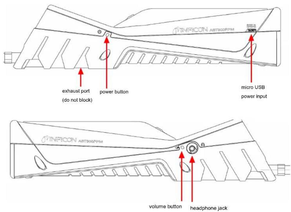
A headphone jack is located on the right side of AST300PPM for listening to the alarm sounds through headphones or earbuds.

WARNING
If attempting to use headphones not supplied by INFICON, be sure to test them carefully to avoid hearing damage.
A volume button is located next to the headphone jack. Press the volume button to toggle from 100% volume, to 50% volume, and to mute. The volume defaults to 100% at startup. When headphones or earbuds are plugged in, the volume toggles between 100% volume and mute.
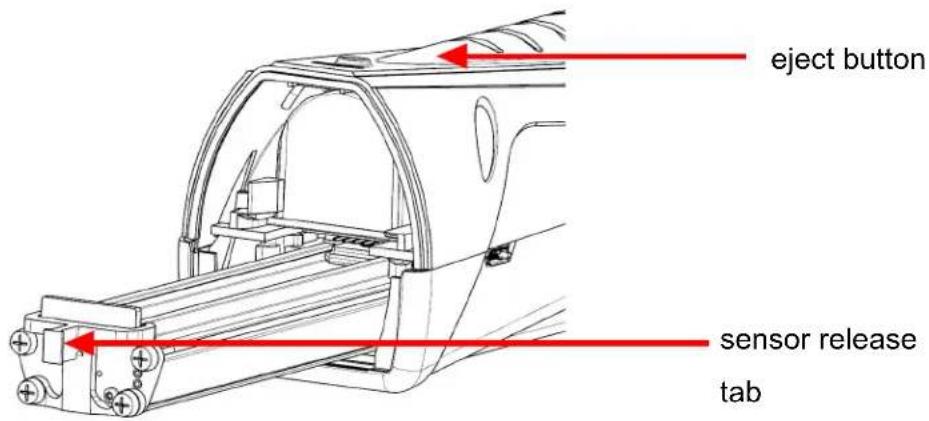
14 Removing and Installing the Lithium Ion Battery
- Press the eject button on the back of AST300PPM and remove the battery door.
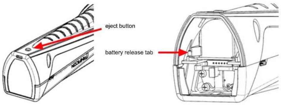
- Remove the battery by moving the battery release tab to the side until the battery begins to eject. Slide the battery out.
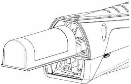
- Re-insert the battery by first aligning the battery with the rails.
natural_image
Technical line drawing of a mechanical component with internal parts and mounting holes (no text or symbols)- Gently push the battery along the rails until the battery release tab engages.
Do not force the battery. If the battery does not slide freely, check the alignment and try again.
- Reinstall the battery door.
15 Removing and Installing the Sensor
AST300PPM uses a cartridge style sensor that is quick and easy to remove and replace in the field. In addition to the standard sensor, INFICON offers a CO_2 specific sensor for use in refrigeration and air conditioning applications. See Replacement Parts and Accessories.
To replace the sensor:
- Press the eject button on the back of AST300PPM and remove the battery door.
- Grasp the sensor release tab and gently pull it out.
- Align the new sensor with the rails.
- Gently push the sensor along the rails until it is fully inserted.
Do not force the sensor. If it does not slide freely, check the alignment and try again. - Reinstall the battery door.
16 Replacing Filters
AST300PPM uses a hydrophobic filter cartridge that allows air and refrigerants to pass through while filtering out water, dirt, and oil. Examine the white cloth to determine if the filter needs to be changed. If the cloth appears discolored, install a new filter. Changing the filter is also an easy troubleshooting step if you suspect your leak detector is not properly detecting refrigerants. A clogged air filter can limit the sample air flow.
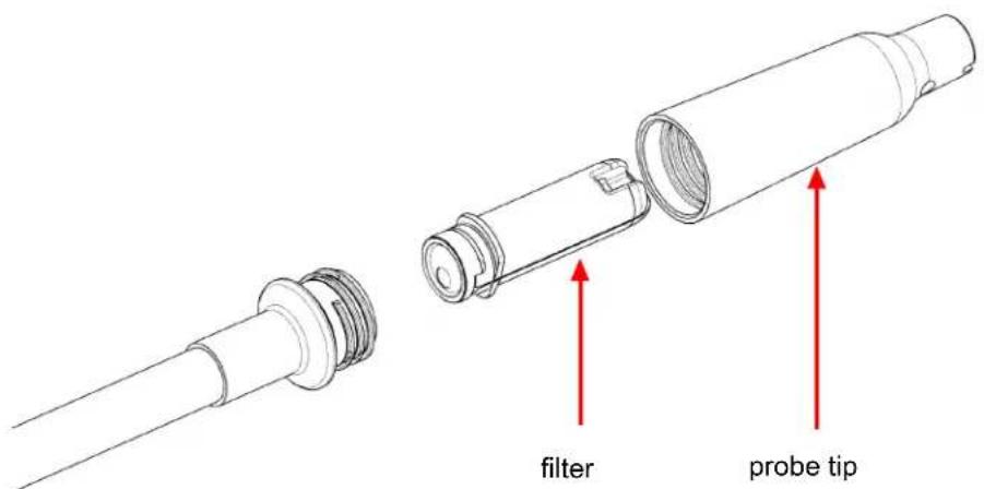

Exposing the filter to water or oil can block air flow. If this occurs, remove the filter with the unit turned off and the probe facing down to avoid getting contaminants in the probe and install a new filter. If the filter is wet, it can be reused once it dries.

CAUTION
Never use the instrument without a probe tip and filter.
To replace the filter:
- Unscrew the probe tip and remove the filter.
- Insert the new filter into the probe.
- Screw the probe tip on. Do not overtighten.
17 Extra-long Probe
AST300PPM includes an extra-long replacement probe for leak checking in hard-to-reach areas.
To install the extra-long probe:
- Unscrew the standard probe from the AST300PPM body using a 10 mm wrench.
- Screw on the extra-long probe to approximately 35 in·lb (4 N·m). Do not overtighten.
- Unscrew the probe tip from the standard probe and remove the filter (or use a new one).
- Insert the filter into the extra-long probe.
- Screw the probe tip onto the extra-long probe. Do not overtighten.
18 Optional Sensors
Optional sensors are available for use in CO_2 (PN 724-701-G2) applications. To use the CO_2 sensor, remove the standard sensor and install the new sensor following the instructions in Removing and Installing the Sensor [▶ 23]. AST300PPM automatically recognizes the sensor type and the MODE indicator illuminates the appropriate color to indicate the sensor type the entire time the sensor is installed. Green indicates CO_2 and orange indicates the standard refrigerant sensor is installed.

While searching for CO_2 leaks, it is recommended to wear a respirator or mask to avoid exhaling CO_2 toward the probe.
WARNING
Exposure to high concentrations of CO_2 or refrigerants is dangerous and can be life-threatening.
The instrument is not for use in toxic or hazardous environments. It is not a personal protection or life-saving device. Always exercise extreme caution in potentially toxic or hazardous environments.

WARNING
This product is not intrinsically safe and should not be used in the presence of explosive fumes, explosive dust, or other explosive chemicals. Use in an environment with flammable refrigerant concentration approaching the LEL could cause an explosion or fire resulting in serious injury, death, or damage to property.
19 Replacement Parts and Accessories
| Earbuds 721-607-G1 | |
| 12 V (dc) car charger 721-605-G1 | |
| AC wall charger (includes plugs for multiple regions) | 721-606-G1 |
| Lithium ion battery 721-702-G1 | |
| Battery charging cradle 721-610-G1 | |
| Battery/charging cradle combination 721-604-G1 | |
| Standard sensor (detects R134a and R1234yf) | 724-701-G1 |
| CO_2 sensor 724-701-G2 | |
| Filter cartridges (quantity, 5) 712-707-G1 | |
| Replacement probe cap 712-705-G1 | |
| Extra-long probe 721-611-G1 | |
| TEK-Check R134a test leak 703-080-G10 | |
| TEK-Check R1234yf test leak 703-080-G12 |
20 Cleaning and Storage
AST300PPM can be cleaned with mild detergent or isopropyl alcohol. Care should be taken to prevent cleaner from entering the instrument. Do not clean with gasoline, acetone, or other aggressive solvents as they may damage the plastic or display.
21 Troubleshooting Guide
| Problem Cause Remedy | ||
The following symbol is displayed: | A battery error has occurred. This can be caused by a failed battery or by the battery being improperly installed, or having a poor connection. | Remove and reinstall the battery. If the problem is not fixed, replace the battery. See Removing and Installing the Lithium Ion Battery. |
The following symbol is displayed: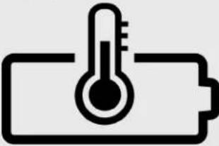 | The battery is above or below the ideal temperature range and may not charge properly. | Allow the battery to return to normal temperature. |
The following symbol is displayed: | A sensor error has occurred. This can be caused by a failed sensor, or by the sensor being improperly installed, or having a poor connection. | Remove and reinstall the sensor. If the problem is not fixed, replace the sensor. See Removing and Installing the Sensor [▶ 23]. |
| The display does not turn on after long-pressing the power button. | The battery level is critically low. | Charge the battery or plug the unit into a charger. |
| The unit turns on, but does not detect refrigerant. | The unit has not completed warm-up (a coffee cup is displayed). | Wait for the warm-up to complete. This takes 45 to 90 seconds. |
| The filter is clogged, restricting the air flow. | Replace the filter cartridge. See Replacing Filters [▶ 24]. | |
| The pump has failed. Listen for the pump sound. If the pump is not making a sound and the battery has a proper charge, contact INFICON. | ||
| The sensitivity is set too low (Pinpoint mode only). | Verify the sensitivity level. For very small leaks, High or Super should be used. | |
| The incorrect sensor is installed. | Verify that the correct sensor is being used (refrigerant sensor or CO_2 sensor). | |
| The reference sample is contaminated (Cloud Hunting mode). | Let AST300PPM run in clean air in Cloud Hunting mode for up to five minutes. | |
| The unit alarms in clean air. | The exhaust port is covered. | Verify that the exhaust port is not covered. |
| The incorrect sensor is installed. | Verify that the refrigerant sensor is installed instead of the CO_2 sensor. | |
| The ppm falls to zero in an area known to be contaminated. | The reference sample may be contaminated. | Let AST300PPM run in clean air in Cloud Hunting mode for up to five minutes. |
| The pump is not making a sound. | The pump has failed. If the battery has a proper charge, contact INFICON. | |
22 Warranty and Liability-Limitation
INFICON warrants your AST300PPM to be free from defects of materials or workmanship for one or two years (depending on region) from the date of purchase. INFICON does not warrant items that deteriorate under normal use, including batteries, sensors, and filters. In addition, INFICON does not warrant any instrument that has been subjected to misuse, negligence, or accident, or has been repaired or altered by anyone other than INFICON. INFICON liability is limited to instruments returned to INFICON, transportation prepaid, not later than thirty (30) days after the warranty period expires, and which INFICON judges to have malfunctioned because of defective materials or workmanship. INFICON liability is limited to, at its option, repairing or replacing the defective instrument or part. This warranty is in lieu of all other warranties, express or implied, whether of MERCHANTABILITY or of FITNESS FOR A PARTICULAR PURPOSE or otherwise. All such other warranties are expressly disclaimed. INFICON shall have no liability in excess of the price paid to INFICON for the instrument plus return transportation charges prepaid. INFICON shall have no liability for any incidental or consequential damages. All such liabilities are EXCLUDED.
23 Returning the Instrument for Warranty or Repair
Contact your wholesaler for warranty evaluation or out-of-warranty repair. Do not return the unit to INFICON directly. All instruments and parts returned to INFICON for repair or credit must be properly packaged, insured, shipped transportation charges prepaid, and must have a Return Material Authorization (RMA) number issued before the material is returned. The RMA number must be marked on all shipping labels and packing slips. Please see your INFICON distributor for assistance. If you have any questions, contact INFICON at 800-344-3304, or contact your local INFICON sales office.
Two Technology Place
East Syracuse, NY 13057
EE. UU.
Business Line Manager – Service Tools
Two Technology Place
natural_image
Technical line drawing of a mechanical component with internal parts and mounting holes (no text or symbols)INFICON Inc. Two Technology Place East Syracuse, NY 13057 USA
Business Line Manager - Service Tools
Two Technology Place
East Syracuse, NY USA 13057
natural_image
Technical line drawing of a mechanical component with internal parts and mounting holes (no text or symbols)DÉCLARATION UE DE CONFORMITÉ
Two Technology Place
East Syracuse, NY 13057
États-Unis
Business Line Manager – Service Tools
Two Technology Place
natural_image
Technical line drawing of a mechanical component with internal parts and mounting holes (no text or symbols)Two Technology Place
East Syracuse, NY 13057
USA
Two Technology Place
East Syracuse, NY USA 13057
QUALSIASI DOMANDA RELATIVA ALLA PRESENTE DICHIARAZIONE O ALLA SICUREZZA DEI PRODOTTI INFICON DEVE ESSERE RIVOLTA, PER SCRITTO, AL RAPPRESENTANTE AUTORIZZATO UTILIZZANDO L'INDIRIZZO DI CUI SOPRA.
natural_image
Technical line drawing of a mechanical component with internal parts and mounting holes (no text or symbols)Two Technology Place
East Syracuse, NY 13057
USA
Two Technology Place
East Syracuse, NY USA 13057
natural_image
Technical line drawing of a vehicle interior showing engine compartment and door (no text or symbols)INFICON Inc. Two Technology Place East Syracuse, NY 13057 USA
Two Technology Place
East Syracuse, NY USA 13057
natural_image
Technical line drawing of a mechanical component with internal parts and mounting holes (no text or symbols)Two Technology Place
East Syracuse, NY 13057
США,
Two Technology Place
East Syracuse, NY CLWA 13057
natural_image
Technical line drawing of a mechanical component with internal parts and mounting holes (no text or symbols)Two Technology Place
East Syracuse, NY 13057
USA
Two Technology Place
East Syracuse, NY USA 13057
WSZELKIE PYTANIA ZWIĄZANE Z. NINIEJSZĄ DEKLARACJA LUB Z. BEZPIECZENSTWEM PRODUKTÓW FIRMY INFICON NALEŻY KIEROWAĆ NA PIŚMIE DO AUTORYZOWANEGO PRZĘDSTAWICIELA POD WYŻEJ WYMIĘNIONYM ADRESEM.
natural_image
Technical line drawing of a mechanical component with internal parts and mounting holes (no text or symbols)Two Technology Place
East Syracuse, NY 13057
USA
Two Technology Place
East Syracuse, NY USA 13057
ALLA FRÅGOR OM DENNA FÖRSÄKRAN ELLER OM SÄKERHETEN HOS INFICONS PRODUKTER SKA STÄLLAS SKRIFTLIGEN TILL BEFULLMÄKTIGAT OMBUD PÅ OVANSTÄENDE ADRESS.
Patent (under behandling)
• Tillämpning #10 2018 206 877.1
• Tillämpning #18171080.7
• Tillämpning # 10 2018 208 826.8
4 D-TEK Stratus
5 Ladda batteriet
bar_stacked
| Category | Value | | -------- | ----- | | Top Blue Segment | 100% | | Middle Yellow Segment | 50% | | Bottom Green Segment | 30% | | Bottom Red Segment | 20% | | Bottom Green Label | 10% | | Bottom Red Label | 5% | | Bottom Green Label | 3% | | Bottom Red Label | 2% | | Bottom Green Label | 1% | | Bottom Green Label | 0.5% | | Bottom Red Label | 0.3% | | Bottom Green Label | 0.2% | | Bottom Red Label | 0.1% | | Bottom Green Label | 0.05% | | Bottom Green Label | 0.03% | | Bottom Red Label | 0.02% | | Bottom Green Label | 0.01% | | Bottom Green Label | 0.005% | | Bottom Red Label | 0.003% | | Bottom Green Label | 0.002% | | Bottom Green Label | 0.001% | | Bottom Red Label | 0.0005% | | Bottom Green Label | 0.0003% | | Bottom Green Label | 0.0002% | | Bottom Red Label | 0.0001% | | Bottom Green Label | 0.00005% | | Bottom Green Label | 0.00003% | | Bottom Red Label | 0.00002% | | Bottom Green Label | 0.00001% | | Bottom Green Label | 0.000005% | | Bottom Red Label | 0.000003% | | Bottom Green Label | 0.000002% | | Bottom Green Label | 0.000001% | | Bottom Red Label | 0.0000005% | | Bottom Green Label | 0.0000003% | | Bottom Green Label | 0.0000002% | | Bottom Red Label | 0.0000001% | | Bottom Green Label | 0.00000005% | | Bottom Green Label | 0.00000003% | | Bottom Red Label | 0.00000002% | | Bottom Green Label | 0.00000001% | | Bottom Green Label | 0.00000001% | | Bottom Red Label | 0.00000001% | | Bottom Green Label | 0.00000001% | | Bottom Green Label | 0.00000001% | | Bottom Red Label | 0.00000001% | | Bottom Green Label | 0.00000001% | | Bottom Green Label | 0.00000001% | | Bottom Red Label | 0, 1, 2, 3, 4, and 5, respectively, with an additional label "Lokaliseringssymbol" at the end.natural_image
Technical line drawing of a mechanical component with internal parts and mounting holes (no text or symbols)
Two Technology Place
East Syracuse, NY 13057
USA
Two Technology Place
East Syracuse, NY USA 13057
natural_image
Technical line drawing of a mechanical component with internal parts and mounting holes (no text or symbols)Two Technology Place
East Syracuse, NY 13057
Verenigde Staten
Business Line Manager – Service Tools
Two Technology Place
East Syracuse, NY VS 13057
VRAGEN OVER DEZE VERKLARING OF DE VEILIGHEID VAN DE PRODUCTEN VAN INFICON MOETEN SCHRIFTELUK GERICHT WORDEN AAN DE BEVOEGD VERTEGENWOORDIGER OP HET BOVENSTAANDE ADRES
natural_image
Technical line drawing of a mechanical component with internal parts and mounting holes (no text or symbols)INFICON Inc. (주소: Two Technology Place East Syracuse, NY 13057 USA)
Two Technology Place
East Syracuse, NY USA 13057
radar
| Status | Count | |--------|-------| | Alert | 65 | | FILLED | 45 | | Low | 25 | | R1234yf PSI (BAR) | 0 | | Other | 150 (10.3) | | Other | 200 (13.8) | | Other | 100 (6.9) |natural_image
Technical line drawing of a mechanical component with internal parts and mounting holes (no text or symbols)RoHS Compliance List
This table is prepared according to provisions of SJ/T 11364.
○: 表示该有害物质在该部件所有均质材料中的含量均在GB/26572规定的限量要求下。
○: Indicates that said hazardous substance contained in all off the homogeneous materials for this part is below the limit requirement of GB/T 26572.
x: 表示该有害物质至少在该部件的某一均质材料中的含量超出GB/26572规定的限量要求。
×: Indicates that said hazardous substance contained in at least one of the homogeneous materials for this part is above the limit requirement of GB/26572.

natural_image
Green circular logo with a lowercase 'e' and two curved arrows, no text or symbols present.
INFICON
Two Technology Place
East Syracuse, NY 13057-9714 USA
Phone: +1.800.344.3304
E-Mail: service.tools@inficon.com
www.inficonservicetools.com
Bonner Strasse 498
D-50968 Cologne, Germany
Phone: +49 221 56788-660
E-Mail:servicetools.europe@inficon.com
www.inficonservicetools-europe.com
Section A, Building 6
108 Shuya Road, Shanghai, China
Phone: +86-21-62093094
Email: reach.china@inficon.com
Korea
Phone: +82-31-206-2890
Email:reach.korea@inficon..com
Japan
Phone: +81-44-322-8901
Email: reach.japan@inficon.com
Singapore
Phone: +65-6631-0303
Email: reach.singapore@inficon.com
Taiwan
Phone: +886-3-5525828
Email: reach.taiwan@inficon.com
Due to our continuing program of product improvements, specifications are subject to change without notice.
All trademarks are the property of their respective owners.
074-746-P16A
©2021 INFICON
- AST300PPM
- Refrigerant Leak Detector with PPM Display
- Declaration of Conformity
- INFICON
- Authorized Representative:
- EC Authorized Representative
- Cautions and Warnings
- Cautions:
- WARNING
- SAE Applications
- Always leak test with the engine off.
- Patents (Pending)
- Charging the Battery
- Turning On the Instrument and Preparing for Use
- Screen Layout and Symbols
- Symbol Description
- Cloud Hunting (Portable Monitor) Mode
- There is no sensitivity setting in Cloud Hunting mode.
- Pinpoint Mode
- Manual Zero Mode
- UV Inspection Light
- R1234yf Check Gauge
- CAUTION
- Earbuds and Volume Control
- Removing and Installing the Lithium Ion Battery
- Removing and Installing the Sensor
- Replacing Filters
- To replace the filter:
- Extra-long Probe
- Optional Sensors
- Cleaning and Storage
- Troubleshooting Guide
- Warranty and Liability-Limitation
- Returning the Instrument for Warranty or Repair
- Ladda batteriet
Brand : INFICON
Model : AST300PPM
Category : Measuring equipment