
AST100 - Measuring equipment INFICON - Free user manual and instructions
Find the device manual for free AST100 INFICON in PDF.

| Product type | Refrigerant leak detector |
| Brand | INFICON |
| Model | AST100 |
| Minimum sensitivity (R134a, static) | 2 g/year |
| Maximum sensitivity (R134a, static) | >50 g/year |
| Minimum sensitivity (R134a, dynamic) | 2 g/year |
| Maximum sensitivity (R134a, dynamic) | >50 g/year |
| Response time | <1 s |
| Zeroing time | 5 to 7 s |
| Operating temperature range | -20 to 50 °C |
| Storage temperature range | -20 to 60 °C |
| Humidity | 95% RH max non-condensing |
| Maximum altitude | 2000 m |
| Power supply | Two D-size alkaline batteries |
| Battery life | Approximately 16 hours |
| Weight (with batteries) | 0.58 kg |
| Sensor | Replaceable, lifespan approximately 100 hours |
| Tip filter | Foam, replaceable (pack of 20) |
| UV lamp | Wavelength ~400 nm |
| Housing cleaning | Household detergent or isopropyl alcohol |
| Warranty | 1 or 2 years depending on region |
| Usage | Indoor/outdoor |
Frequently Asked Questions - AST100 INFICON
User questions about AST100 INFICON
0 question about this device. Answer the ones you know or ask your own.
Ask a new question about this device
Download the instructions for your Measuring equipment in PDF format for free! Find your manual AST100 - INFICON and take your electronic device back in hand. On this page are published all the documents necessary for the use of your device. AST100 by INFICON.
USER MANUAL AST100 INFICON
natural_image
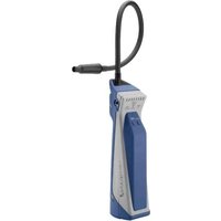
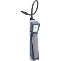
Blue handheld medical device with coiled cable, no visible text or symbolsOperating Manual
AST100
Refrigerant Leak Detector
English · Español · Deutsch · Français · Italiano · 中文 · 日本語
English.... 3
Deutsch 14
Español.... 27
Français.... 39
Italiano 52
中文 64
日本語 75
Table of Contents
1 AST100 4
2 Getting Started.... 4
3 How to Install the Alkaline Batteries.... 5
4 How to Install or Change the Sensor.... 5
5 Using the Instrument.... 6
5.1 Find Leaks 6
5.2 Change the Filter 7
5.3 Cleaning and Storage 7
5.4 SAE Recommended Leak Test Procedure....7
6 UV Inspection Light....9
7 Troubleshooting 10
8 Return Authorization Procedure.... 11
9 Specifications 11
10 Replacement Parts and Accessories.... 12
11 Warranty and Liability-Limitation.... 12
1 AST100
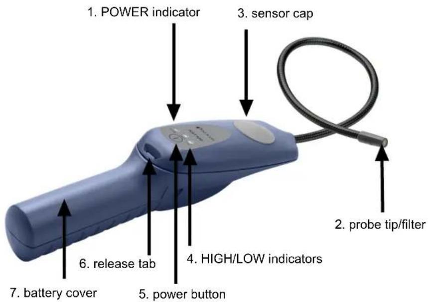
WARNING
This symbol is used to alert the user to the presence of important operating and maintenance instructions in the literature accompanying the instrument.
INFICON ^® is a trademark of INFICON Holding AG.
2 Getting Started
1 Install the batteries. See How to Install the Alkaline Batteries [▶ 5].
2 Install the sensor. See How to Install or Change the Sensor [▶ 5].
⇒ The installation of the batteries and the sensor is required before use.
3 Long-press the power button to turn AST100 On or Off.
4 Wait for AST100 to warm-up. All three indicators illuminate and AST100 alarms during warm-up. When the HIGH indicator starts flashing and AST100 beeps about one beep per second, warm-up is complete.
5 To cycle through low, medium and high sensitivity modes, press the Power button. HIGH sensitivity is the default setting.
3 How to Install the Alkaline Batteries
1 Remove the battery cover by releasing the latch and sliding the cover down and off the handle. You may need a screwdriver, or similar tool, to do this.
2 Install two "D" size alkaline batteries.
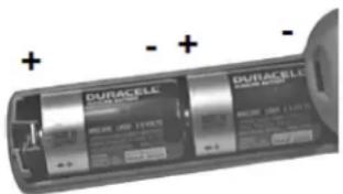
3 Reinstall the battery cover by aligning it with the handle and sliding it up until the latch engages.
- A low battery is indicated when the green POWER indicator flashes. AST100 may continue to operate for up to one hour after this occurs.
- A dead battery is indicated by the POWER and HIGH indicators flashing.

Dispose of the depleted alkaline batteries according to the applicable state and local regulations. In the absence of such regulations, recycle and/or dispose of the batteries through a voluntary waste recycling program.
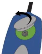
4 How to Install or Change the Sensor
A new AST100 is shipped with its sensor packed separately. The sensor must be installed before use. This specialized sensor operates for approximately 100 hours before it needs to be replaced.
1 Remove the rubber sensor cover by lifting it at the outer edge.
natural_image
Illustration of a blue and green object with a circular knob and arrow, no text or symbols present.2 If you are replacing a worn-out sensor, remove the worn-out sensor by pulling it straight out of the socket and discard it.
WARNING
The worn-out sensor may be hot.
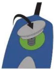
3 Remove the new sensor from its packaging and carefully align the three sensor leads (the small wires coming out of the bottom of the "can") with the three holes in the sensor socket. Insert the leads into the holes by gently pressing straight down on the sensor until the sensor leads contact the bottom of the socket. Be careful not to bend the sensor leads.
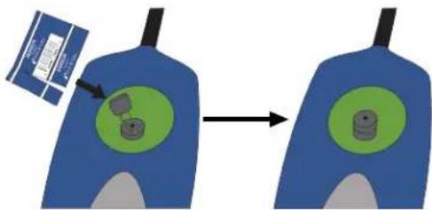
4 Reinstall the rubber sensor cover by pressing it down firmly around the edges. Be sure the edges of the cover are flat against the surface of the detector.
natural_image
Illustration of a mechanical component with a green base and black tip, no visible text or symbols5 Using the Instrument
WARNING
Do not operate AST100 in the presence of gasoline, natural gas, propane, or in other combustible atmospheres.
5.1 Find Leaks

A sudden whipping of the leak detector probe or blowing into the probe tip affects the air flow over the sensor and causes AST100 to alarm.
1 Turn AST100 on and wait for the warm-up to complete.
2 Place the tip of the probe as close as possible to the site of the suspected leak. Try to position the probe within 1/4 in. (5 mm) of the possible leak source.
3 Slowly (approximately 1 to 2 in. (2.5 to 5 cm) per second) move the probe past each possible leak point.
It is important to move the tip of the probe past the leak. If held on a leak, the auto zero feature gradually zeroes out the leak signal.
4 When the instrument detects a leak, it beeps more rapidly and the indicator flash rate increases to signal the leak.
5 When AST100 signals a leak, pull the probe away from the leak for a moment, then bring it back to pinpoint the location. If the leak is large, toggle sensitivity to LOW to make it easier to find the exact site of the leak.
6 Return sensitivity to HIGH before searching for additional leaks.
7 When finished leak testing, turn AST100 off.
5.2 Change the Filter
The foam filter at the probe tip should be replaced if it becomes plugged with water or oil or appears dirty. To replace the filter, pull out the old filter (with a paper clip or similar device). Insert the new filter.
5.3 Cleaning and Storage
AST100's plastic housing can be cleaned with standard household detergent or isopropyl alcohol. Care should be taken to prevent the cleaner from entering the instrument. Since gasoline and other solvents may damage the plastic, protect AST100 from contact with these substances.

Do not allow cleaners or isopropyl alcohol to enter the sensor as it may become contaminated. Replace the sensor if contamination occurs.
5.4 SAE Recommended Leak Test Procedure

Never attempt to operate the A/C system when it is charged with tracer gas.
√ Always leak test with the engine and the A/C system turned off.
1 Charge the A/C with sufficient refrigerant to attain a gauge pressure appropriate for the ambient temperature and the particular refrigerant. Using the appropriate refrigerant type pressure-temperature chart, determine the expected system pressure. Do not continue to charge once this pressure is reached (unless the test is being performed at higher ambient, as noted in 5.1 of SAE J1628), as the pressure will not increase with added refrigerant once the saturation pressure is reached. At temperatures below 15^ C ( 59^ F), leaks may not be measurable since this pressure may not be achieved. As a preliminary check to find a gross leak, listen for a hissing noise as refrigerant is added. If a hissing is heard, determine the source and repair the leak before adding more refrigerant.
2 Take care not to contaminate the detector probe tip if the part being tested is contaminated. If the part is particularly dirty, it should be wiped off with a dry shop towel or blown off with shop air. No cleaners or solvents should be used because many electronic detectors are sensitive to their ingredients.
3 Turn off any shop fans and close the doors to the outside or park the vehicle in a still-air section of the shop to minimize air movement in the leak detection area. Blowing air dilutes the refrigerant accumulation at the joint, often below the detection range.
4 Visually trace the entire refrigerant system and look for signs of air-conditioning lubricant leakage, damage, and corrosion on all lines, hoses, and components.
5 Warm-up the detector. Based on the estimated leakage rate of the entire system, set the detector to the appropriate sensitivity. Check each questionable area with the detector probe, as well as all fittings, hose-to-line couplings, refrigerant controls, service ports with caps in place, brazed and welded areas, and areas around attachment points and hold-downs on lines and components.
6 Regardless of the system refrigerant charge amount, it is likely that performance issues will occur when the leak rate is 14 g/yr and higher. It is important to minimize system refrigerant loss to assure that maximum cooling performance is achieved. System design leakage varies depending upon the component technology of the system being serviced, and this must be considered in diagnosis. Comparing the identifiable g/yr leak rate of all connections for the system being serviced should be considered when identifying components that need replacement.
New, small capacity systems are likely to have leak rates of under 4 g/yr for joints, so a refrigerant leak rate of 4 g/yr or greater from a joint is likely to be serviceable. On large capacity systems of older system designs, most of the joints checked had a leakage rate of less than 14 g/yr Any leak greater than 14 g/yr indicates that the leak needs to be repaired. Using the leak detector probe, follow the refrigerant system around in a continuous path so that no areas of potential leaks are missed. If a leak is found, continue to test the remainder of the system.
At each area checked, move the probe around the location, at a rate no more than 75 mm/s (3 in./s), and no more than 9.5 mm (3/8 in.) from the surface, completely encircling the fittings, joints, service valves, switches and sensors. Slower and closer movement of the probe greatly improves the likelihood of finding a leak.
7 One way to verify a suspected leak is to blow shop air into the area of the suspected leak to clear the area of refrigerant, and if necessary, repeat the check of the area. In cases of very large leaks, blowing out the area with shop air often helps locate the exact position of the leak. Another method is to recheck for the leak with the sensitivity switch on higher (and if applicable lower) sensitivity switch positions. This also may help the technician estimate the size of a leak.
8 When testing for a leak at the compressor, move the probe along the compressor body joints, around the pressure relief valve and any switches, then all around the compressor nose area (compressor shaft seal). Many compressor shaft seal leaks only occur during compressor operation, so quantifying the leakage rate or verifying the existence of a shaft seal leak poses special problems, as the electronic leak detector test is made with the system off. The shaft seal is on the low-pressure side of the system, which adds to the difficulty. Leak testing of the evaporator core also poses special issues (see section 9 of SAE J1628). Although some refrigerant loss past shaft seals is normal, any triggering of an electronic leak detector on settings below 14 g/yr with the system off may indicate a significant leak has been found if no other leaks can be located. Refer also to sections 6 and 7 of SAE J1628.
9 Following any service to the vehicle's air conditioning refrigerant circuit, a leak test of the repaired components, the service ports, and the entire refrigerant circuit to assure there are no additional system refrigerant leaks should be performed.
6 UV Inspection Light
The UV inspection light emits a beam of light approximately 400 nm in wavelength, which illuminates the fluorescent dye that is commonly installed in automotive AC systems at the factory. Use the UV inspection light to quickly check an area for leaks in a system known to contain dye, or to verify a leak after locating the leak source with your leak detector. INFICON recommends using multiple leak detection methods to verify a leak.
WARNING
Do not point UV light at people or animals.
UV light can cause damage to the eyes or blindness.
7 Troubleshooting
Except for the batteries and the sensor, the internal parts of the AST100 are not user serviceable. If you experience a problem with AST100, see the Troubleshooting Table below to determine how to remedy the problem. If you cannot remedy the problem, take AST100 to your wholesaler for evaluation.
| PROBLEM CAUSE REMEDY | ||
| 1. The instrument has poor sensitivity. AST100 does not find leaks. | 1a. The sensor has reached the end of its useful life. | 1a. Replace the sensor. See How to Install or Change the Sensor [ 5]. |
| 1b. The sensitivity is set to LOW instead of HIGH. | 1b. Set the sensitivity to HIGH and scan for the leak again. | |
| 2. AST100 responds slowly to a leak. | 2a.There is a dirty or wet filter. | 2a. Replace the filter. See Change the Filter [ 7]. |
| 2b. There is a failure in the pumping system. | 2b. Turn AST100 on and listen for a high-pitched motor sound. If you do not hear the motor, return AST100 to your wholesaler for evaluation. | |
| 2c. The sensor cover is not sealed. | 2c. Make sure the sensor cover is properly installed. See How to Install or Change the Sensor [ 5]. | |
| 3. The instrument does not power up. | 3a. The batteries are worn out. | 3a. Install a new set of batteries. See How to Install the Alkaline Batteries [ 5]. |
| 3b. The batteries have been improperly installed. | 3b. Check the battery installation. See How to Install the Alkaline Batteries [ 5]. | |
| 4. There are false alarms.AST100 alarms when the probe is moved or bumped. | 4a. The sensor leads are bent. | 4a. Remove the sensor and inspect the leads. Straighten the leads with needle nose pliers, if necessary, and reinstall the sensor. |
| 4b. Moisture was absorbed by the sensor during a long period without use. | 4b. Run AST100 for at least 20 minutes. The absorption of moisture does not affect the life or sensitivity of the sensor. |
8 Return Authorization Procedure
All defective AST100s should be returned to your wholesaler for warranty evaluation. If you have any questions, please contact INFICON at 800-344-3304.

Do not return your defective unit directly to the factory without first contacting your wholesaler.
9 Specifications
| Usage indoor/outdoor | |
| Minimum sensitivity high sensitivity 0.25 oz./yr (7 g/a) | |
| Operating temperature range ^1 | -20°C to +50°C (-4°F to 122°F) |
| Storage temperature range -20°C to +60°C (-4°F to + 140°F) | |
| Humidity 95% RH NC maximum | |
| Altitude 2000 m (6500 ft.) | |
| Power supply two “D” cell alkaline batteries | |
| Battery life approximately 16 hours | |
| Pollution degree 2 | |
| Overvoltage category 2 | |
| Weight (with batteries) 0.58 kg (1.28 lb.) | |
^1 The instrument may be operated for a limited time in lower temperature environments.
Specification Table in Accordance with EN 14624
| Minimum sensitivity to R134a, fixed (static) | 2 g/yr |
| Upper leak detection limit to R134a, fixed (static)* | >50 g/yr |
| Minimum sensitivity to R134a, moving (dynamic)* | 2 g/yr |
| Upper leak detection limit to R134a, moving (dynamic) | >50 g/yr |
| Minimum response/detection time < 1 s | |
| Zeroing time 5-7 s | |
| Recovery time for 50 g/yr exposure* 12 s | |
| Minimum sensitivity in contaminated environment | 2 g/yr |
| Calibration frequency Check annually with calibrated leak standard. | |
*Upper leak detection limit is not specified by INFICON as there is no upper limit to the size of the leak the detector is able to detect. As no 50 g/yr leak standard was available during testing, a 31 g/yr leak was substituted.
10 Replacement Parts and Accessories
Replacement parts and accessories for your INFICON AST100 Refrigerant Leak Detector are available through your local dealer.
| Replacement sensor 703-020-G1 |
| Tip filters, package of 20 705-600-G1 |
11 Warranty and Liability-Limitation
INFICON warrants your AST100 to be free from defects of materials or workmanship for one or two years (depending on region) from the date of purchase. INFICON does not warrant items that deteriorate under normal use, including batteries, sensors, and filters. In addition, INFICON does not warrant any instrument that has been subjected
to misuse, negligence, or accident, or has been repaired or altered by anyone other than INFICON. INFICON liability is limited to instruments returned to INFICON, transportation prepaid, not later than thirty (30) days after the warranty period expires, and which INFICON judges to have malfunctioned because of defective materials or workmanship. INFICON liability is limited to, at its option, repairing or replacing the defective instrument or part. This warranty is in lieu of all other warranties, express or implied, whether of MERCHANTABILITY or of FITNESS FOR A PARTICULAR PURPOSE or otherwise. All such other warranties are expressly disclaimed. INFICON shall have no liability in excess of the price paid to INFICON for the instrument plus return transportation charges prepaid. INFICON shall have no liability for any incidental or consequential damages. All such liabilities are EXCLUDED.
natural_image
Illustration of a blue and green device with a circular component and a black arrow indicating rotation (no text or symbols)natural_image
Illustration of a mechanical device with a rotating knob and green base (no text or symbols)natural_image
Illustration of a blue container with a green interior and a black handle, showing a curved arrow indicating rotation (no text or symbols)flowchart
graph LR
    A["Blue container with green circles"] --> B["Green circular component with gray parts"]
natural_image
Illustration of a mechanical component with a green base and black tip, no visible text or symbolsnatural_image
Illustration of a blue and green object with a black arrow indicating rotation (no text or symbols)natural_image
Illustration of a blue mechanical component with a green circular base and a black tip, no text or symbols present.natural_image
Illustration of a blue and green object with a circular top and arrow, no text or symbols present.natural_image
Illustration of a mechanical device with a green circular base and black pointer (no text or symbols)natural_image
Illustration of a blue and gray device with a black pointer and green base (no text or symbols)5 使用仪器
警告
natural_image
Illustration of a blue and green object with a black arrow indicating rotation (no text or symbols)natural_image
Illustration of a mechanical component with a rotating shaft and circular base (no text or symbols)5 本装置の使用
警告
Two Technology Place
East Syracuse, NY 13057-9714 USA
Phone: +1.800.344.3304
E-Mail: service.tools@inficon.com
www.inficonservicetools.com
Bonner Strasse 498
D-50968 Cologne, Germany
Phone: +49 221 56788-660
E-Mail:servicetools.europe@inficon.com
www.inficonservicetools-europe.com
Section A, Building 6
108 Shuya Road, Shanghai, China
Phone: +86-21-62093094
Email: reach.china@inficon.com
Korea
Phone: +82-31-206-2890
Email:reach.korea@inficon..com
Japan
Phone: +81-44-322-8901
Email: reach.japan@inficon.com
Singapore
Phone: +65-6631-0303
Email: reach.singapore@inficon.com
Taiwan
Phone: +886-3-5525828
Email: reach.taiwan@inficon.com
Due to our continuing program of product improvements, specifications are subject to change without notice.
All trademarks are the property of their respective owners.
074-740-P16B
©2022 INFICON
- AST100
- Refrigerant Leak Detector
- Table of Contents
- AST100
- WARNING
- Getting Started
- How to Install the Alkaline Batteries
- How to Install or Change the Sensor
- Using the Instrument
- Find Leaks
- Change the Filter
- Cleaning and Storage
- SAE Recommended Leak Test Procedure
- UV Inspection Light
- Troubleshooting
- Return Authorization Procedure
- Specifications
- Replacement Parts and Accessories
- Warranty and Liability-Limitation
- 使用仪器
- 警告
- 本装置の使用
Brand : INFICON
Model : AST100
Category : Measuring equipment