
D-TEK Pro - Measuring equipment INFICON - Free user manual and instructions
Find the device manual for free D-TEK Pro INFICON in PDF.

| Product type | Refrigerant leak detector and portable monitor |
| Sensor type | Infrared |
| Compatible refrigerants | All CFCs, HCFCs, HFCs, HFOs and blends (including A2L) |
| Sensitivity (EN14624) | R134a: 0.5 g/year; R1234yf: 0.5 g/year |
| Display resolution | 0.1 ppm |
| Display range | 0–10,000 ppm |
| Accuracy | ±0.5 ppm ±10% of reading |
| Operating temperature | -20 to 50 °C |
| Storage temperature | -20 to 60 °C |
| Humidity | 90% RH non-condensing |
| Max altitude | 2000 m |
| Battery | Rechargeable lithium-ion, ~14 h battery life |
| Charging time | ~3 hours |
| Input power | 12 V DC, 2 A |
| Sensor lifespan | 5000 hours typical operation |
| Protection rating | IP40 |
| Weight (without probe or hose) | 1.37 kg |
| Connectivity | Bluetooth, integrated GPS |
| Functions | Cloud Hunting, fresh air zero, data logging, mobile app |
| Included accessories | Hose, probe with filter, wall charger, phone holder, case with shoulder strap |
| Warranty | 1 to 2 years depending on region, excluding battery/sensor/filters |
Frequently Asked Questions - D-TEK Pro INFICON
User questions about D-TEK Pro INFICON
0 question about this device. Answer the ones you know or ask your own.
Ask a new question about this device
Download the instructions for your Measuring equipment in PDF format for free! Find your manual D-TEK Pro - INFICON and take your electronic device back in hand. On this page are published all the documents necessary for the use of your device. D-TEK Pro by INFICON.
USER MANUAL D-TEK Pro INFICON
natural_image
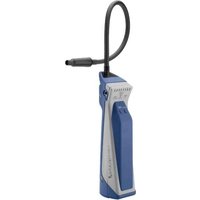
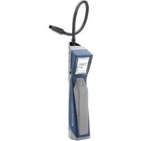
Medical device labeled 'INFICON D-TEK® Pro' with digital display and tubing, no visible text or symbols on the device itself.Operating Manual
D-TEK PRO
Refrigerant Leak Detector
English....3
Español 21
Deutsch.... 39
Italiano.... 59
Français 79
日本語....99
中文....119
한국어 137
Table of Contents
1 Disclaimer and Copyright 4
2 Cautions and Warnings 4
3 Specifications 6
4 What is Cloud Hunting? 7
5 D-TEK Pro 7
6 Screen Layout and Symbols 7
7 Operation 9
7.1 Getting Started.... 9
7.2 Home Screen 11
7.3 Checking for Leaks 11
7.4 Settings Menu 12
7.5 Fresh Air Zero.... 13
7.6 Data Log Settings.... 13
7.7 Connectivity Settings 14
8 App 14
9 Accessories 15
10 Maintenance 17
11 Cleaning and Storage 19
12 Replacement Parts and Accessories 19
13 Troubleshooting Guide 19
14 Warranty and Liability-Limitation 20
15 Returning the Instrument for Warranty or Repair 20
1 Disclaimer and Copyright
Disclaimer
The information contained in this manual is believed to be accurate and reliable. However, INFICON assumes no responsibility for its use and shall not be liable for any special, incidental, or consequential damages related to the use of this product.
Due to our continuing program of product improvements, specifications are subject to change without notice.
Copyright
©2025 All rights reserved.
Reproduction or adaptation of any part of this document without permission is unlawful.
D-TEK and D-TEK Stratus are registered trademarks of INFICON.
Cloud Hunting is a registered trademark of INFICON.
Apple, the Apple logo, and iPhone are trademarks of Apple Inc., registered in the U.S. and other countries. App Store is a service mark of Apple Inc.
Google Play and the Google Play logo are trademarks of Google LLC.
The Bluetooth ^® word mark and logos are registered trademarks owned by the Bluetooth SIG, Inc., and any use of such marks by INFICON is under license.
Other trademarks and trade names are those of their respective owners.
2 Cautions and Warnings
Read this manual carefully before using the instrument. Pay particular attention to WARNINGS, CAUTIONS, and NOTICES. Using the product in any way other than specified in this manual may impair any protections provided by the product. Use only accessories that have been supplied or recommended by INFICON.
Cautions:
- Only use a certified charger/cord with an output of 12V(dc), 2 A.
- The battery is not user serviceable. Battery replacement should only be done by INFICON or an authorized service center.
- Keep the device out of extremely high or low temperature locations.
- Do not expose the battery to liquid.
- Do not use the device if you notice any damage to the battery.
- Do not disassemble or modify the battery.
- Handle and dispose of the battery per local regulations.
- If the recharging operation fails to complete, even when the specified recharging time has elapsed, immediately stop further recharging.
- Do not leave the battery unattended while charging.
- Unplug the charger when the battery is fully charged.
-
Improper use or disposal of lithium-ion batteries can cause a fire.
• High RF environments may cause a false alarm. -
Do not charge the battery below 0^ (32°F).
- Charging above room temperature is not recommended as it can reduce the battery performance and overall battery life.

WARNING
This symbol alerts the user to the presence of important operating and maintenance (servicing) instructions.

WARNING
Exposure to high concentrations of CO_2 or refrigerants is dangerous and can be life-threatening.
The instrument is not for use in toxic or hazardous environments. It is not a personal protection or life-saving device. Always exercise extreme caution in potentially toxic or hazardous environments.

WARNING
This product is not intrinsically safe and should not be used in the presence of explosive fumes, explosive dust, or other explosive chemicals. Use in an environment with flammable refrigerant concentration approaching the LEL (lower explosive limit) could cause an explosion or fire resulting in serious injury, death, or damage to property.
This device complies with Part 15 of the FCC Rules. The device meets the requirements for modular transmitter approval as detailed in FCC public Notice DA00-1407 transmitter. Operation is subject to the following two conditions: (1) This device may not cause harmful interference, and (2) This device must accept any interference received, including interference that may cause undesired operation.
This equipment has been tested and found to comply with the limits for a Class B digital device, pursuant to Part 15 of the FCC Rules. These limits are designed to provide reasonable protection against harmful interference in a residential installation. This equipment generates uses and can radiate radio frequency energy and, if not installed and used in accordance with the instructions, may cause harmful interference to radio communications. However, there is no guarantee that interference will not occur in a particular installation. If this equipment does cause harmful interference to radio or television reception, which can be determined by turning the equipment off and on, the user is encouraged to try to correct the interference by one or more of the following measures:
- Reorient or relocate the receiving antenna.
- Increase the separation between the equipment and receiver.
- Connect the equipment into an outlet on a circuit different from that to which the receiver is connected.
- Consult the dealer or an experienced radio/TV technician for help.
Changes or modifications not expressly approved by the party responsible for compliance could void the user's authority to operate the equipment.
To comply with the FCC RF exposure compliance requirements, this device and its antenna must not be co-located or operating to conjunction with any other antenna or transmitter.
3 Specifications
| Usage Indoor or outdoor | |
| Sensor type Infrared | |
| Compatible refrigerants All CFCs, HCFCs, HFCs, HFOs, and blends (including A2Ls) | |
| Sensitivity (tested to EN14624 standard) | |
| • R134a 0.02 oz./yr (0.5 g/yr) | |
| • R1234yf | 0.02 oz./yr (0.5 g/yr) |
| Display resolution 0.1 ppm | |
| Display range 0-10000 ppm | |
| Accuracy ± 0.5 ppm ± 10% of reading | |
| Operating temperature -20 to 50°C (-4 to 122°F) | 1 |
| Storage temperature -20 to 60°C (-4 to 140°F) | 2 |
| Charging temperature 0 to 45°C (32 to 113°F) | |
| Humidity 90% RH, Non-condensing | |
| Altitude 2000 m (6500 ft.) | |
| Battery type Lithium ion rechargeable battery | |
| Battery life ~14 hours | |
| Charging input type Barrell connector | |
| Charging time | ~3 hours |
| Input voltage | 12 V (dc) |
| Input current | 2.0 A |
| Sensor life | 5000 hours of operation typical |
| Ingress protection | IP40 |
| Pollution degree | 2 |
| Overvoltage category | 2 |
| Weight (without probe and hose) | 3.02 lb (1.37 kg) |
^1 Use in temperatures below 0^ C ( 32^ F) or above 40^ C ( 104^ F) should be limited. Extended warm-up time is recommended before use in low temperature environments.
^2 For extended storage over 1 month, recommended max storage temp is 23^ C ( 74^ F).
Patents
• Pat. US 10352848B2
• Pat. EP 3163299B1
• Pat. CN 108603871B
• Pat. JP 6789290B2
• Pat. CN 108885198A
• Pat. EP 3163166B1
• Pat. JP 7042742B2
• Pat. US 10866225B2
• Pat. CN 108885198B
4 What is Cloud Hunting?
When refrigerant leaks from a system, it does not disperse evenly in the air. The concentration of refrigerant is usually higher near the source of the leak. The density of refrigerants is also different than that of air, so it tends to form “clouds” in the air, typically closer to the floor. These clouds are colorless and odorless for most refrigerants. When leak checking with a traditional leak detector, it will likely alarm when walking into a refrigerant cloud. This does not help you find the leak, because the cloud may not be near the leak source.
INFICON's Clound Hunting ^ leak detectors like D-TEK Stratus ^ and D-TEK Pro use patented technology to display the refrigerant concentration in the air in parts per million (ppm). This allows you to read the display and follow the number to find areas of higher concentration, leading you straight to the leak source.
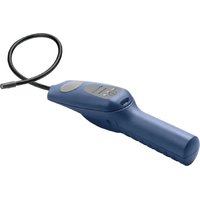
5 D-TEK Pro
D-TEK Pro is a high-sensitivity refrigerant leak detector and portable monitor designed to find refrigerant clouds and detect the smallest of refrigerant leaks using just a single mode.
Continue reading this manual for more information on operating your new D-TEK Pro.
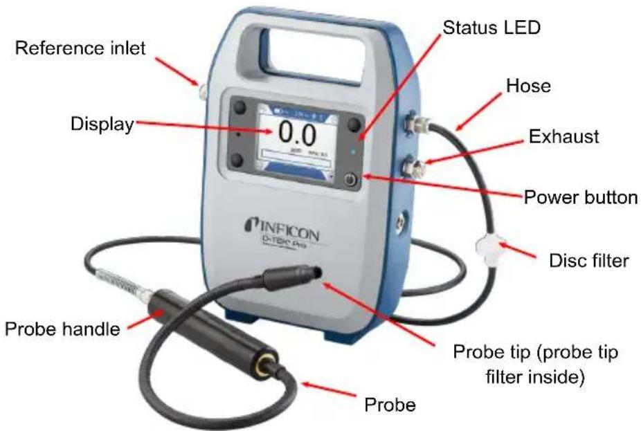
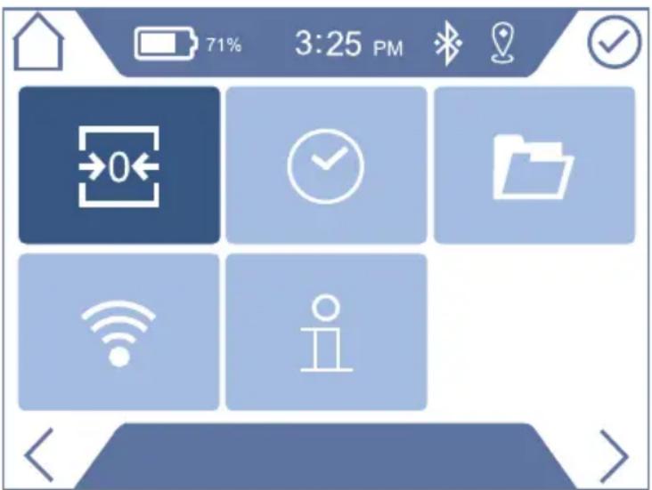
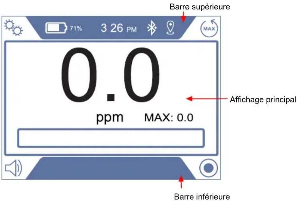
6 Screen Layout and Symbols
D-TEK Pro uses the display screen for nearly all indicators and information. The display consists of a top bar, main display, and a bottom bar. Symbols displayed in each of the 4 corners indicate the current function of the corresponding button.

Top bar: The top bar includes the battery symbol and charge %, time, GPS, and bluetooth status.
| Symbol Description | |
 | Battery charge is 75-100% |
 | Battery charge is 50-74% |
 | Battery charge is 30-49% |
 | Battery charge is 10-29% |
 | Battery charge is <10% |
 | Battery is charging |
 | Bluetooth is turned on |
 | Bluetooth device is connected |
| [70HH] | GPS signal active; symbol flashes when searching for GPS signal |
NOTE: Battery percentages are approximate estimates.
Main display: The main display shows relevant information for the current screen. D-TEK Pro starts up in the home screen, which also functions as the operate screen for regular use.
Bottom bar: The bottom bar display information about the current display screen.
Navigation Symbols
| Symbol Description | |
 | Enter the settings menu or return to the settings menu |
 | Scroll left/right/up/down through options |
 | Enter the selected settings menu or sub-menu; accept and save a setting change |
 | Return to the home screen |
 | Start logging data |
 | Stop a current log |
Status LED
| Color Meaning | |
| Yellow Startup process is running. | |
| Green Unit is powered off and battery is | charging. Extinguishes when fully charged. |
| Blue Unit is on and running normally. | |
| Red Indicates an error or failure is present. | |
7 Operation
7.1 Getting Started
Charging the Battery
D-TEK Pro uses a rechargeable lithium-ion battery. Using the supplied charger, a dead battery can be charged to 100% in approximately 3 hours. A full charge typically lasts about 14 hours of operation, depending on the operating temperature. An on-screen indicator displays the battery charge level.

D-TEK Pro must be charged before initial use. The unit cannot be operated the first time until it is charged.
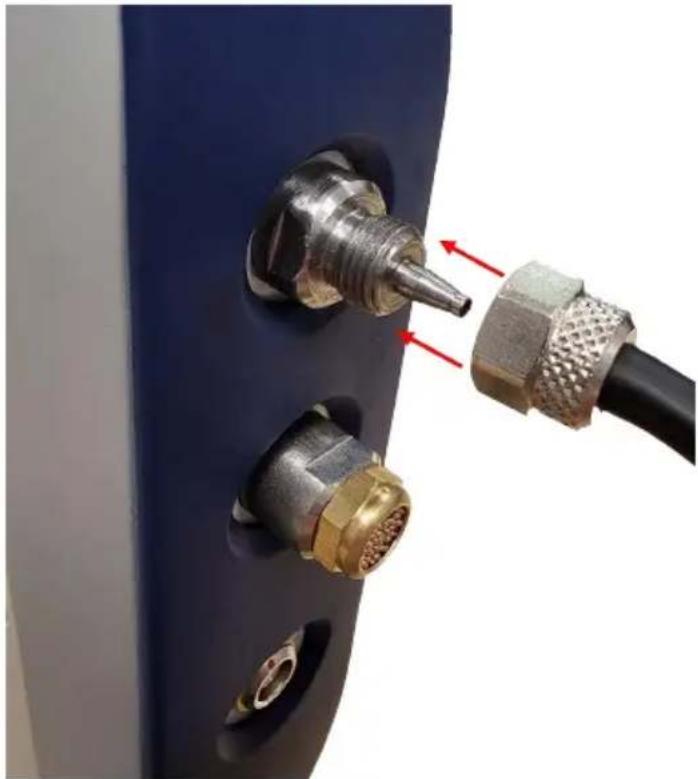
Connecting the Sampling Hose and Probe Assembly
D-TEK Pro ships with the hose and probe assembly already connected, but if you need to remove and reattach the hose, follow these instructions. NOTE: It's best to always perform a visual inspection of all components before assembling and turning on the unit. Check all filters and hoses for debris or moisture and replace if necessary.

CAUTION
Never operate D-TEK Pro without complete hose and probe assembly connected with all filters in place. Failure to do so may result in damage to the unit not covered under warranty.
1 Carefully place the hose with nut over the inlet fitting on D-TEK Pro. NOTE: If the nut falls off of the hose, push the end of the hose back through the hole in the nut.
natural_image
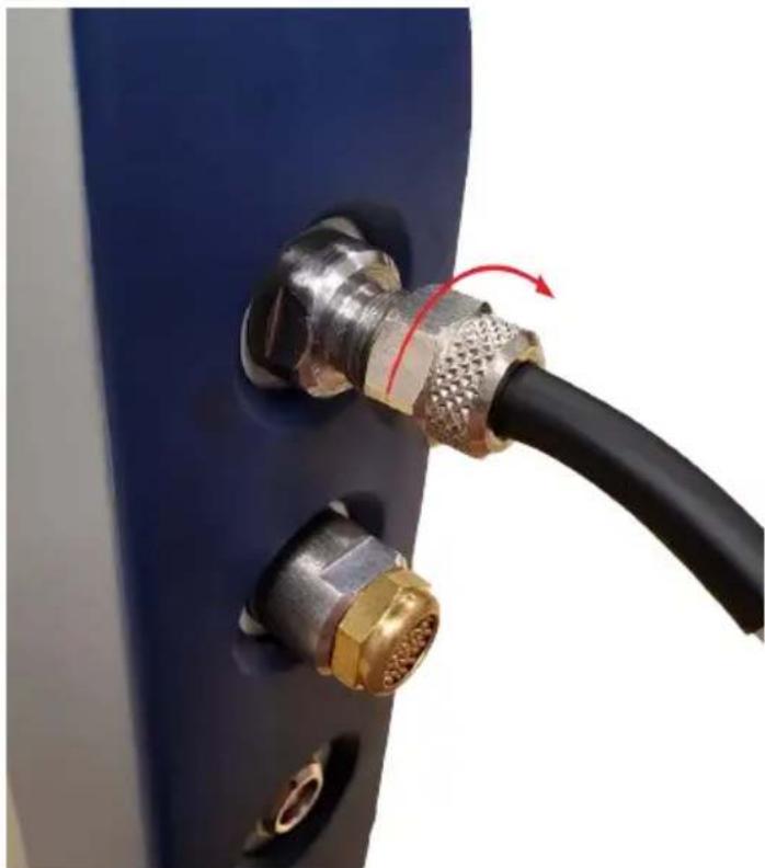
Close-up of a metallic connector with two brass connectors inserted, connected to a black cable (no text or symbols visible)2 Hand-tighten the nut. Be careful not to over-tighten.
natural_image
Close-up of a black cable with metallic connectors and a red rotation arrow indicating cable movement (no text or symbols)Turning On the Instrument and Preparing for Use
Long press the power button (bottom right button) to turn D-TEK Pro On or Off. D-TEK Pro will briefly display the firmware version on startup, then continue through a warmup and self diagnosis.
i
If the screen does not turn on, the battery may need charging.
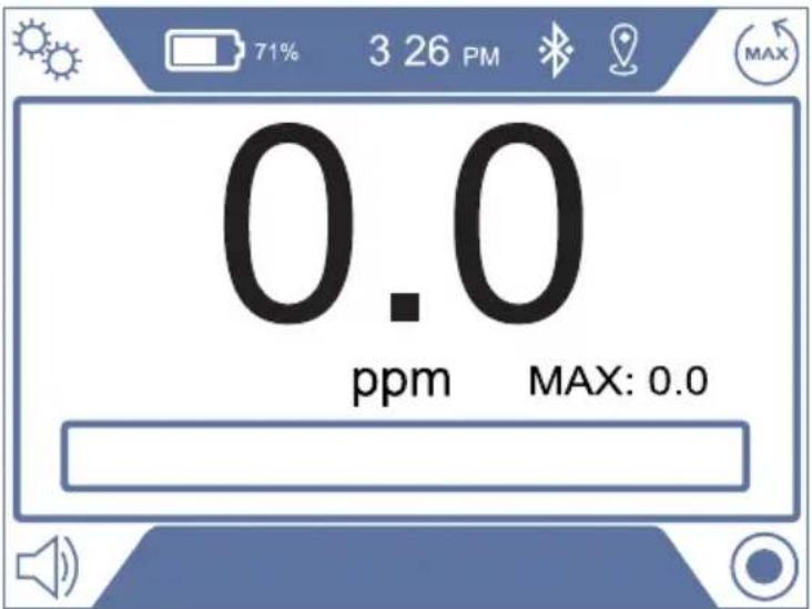
7.2 Home Screen
D-TEK Pro starts up automatically in the home screen and will immediately display background refrigerant in parts per million (ppm).
On the home screen, press the corresponding button to perform the following actions:
| Symbol Description | |
 | Reset the max value to zero |
 | Mute or unmute |
 | Enter the settings menu |
 | Start logging data |
7.3 Checking for Leaks
D-TEK Pro uses a single mode and sensitivity setting, making leak checking easier than ever.
Cloud Hunting
1 Slowly move through the suspect areas and observe the ppm reading.
2 Follow the ppm reading to find areas of higher refrigerant concentration. The higher the number, the higher the concentration.
3 The maximum reading is saved on the screen next to MAX. To reset the maximum reading, press the MAX reset button.
Pinpointing Leaks
1 Place the probe tip as close as possible to the suspected leak (do not block the air flow).
2 Slowly move the probe past each possible leak point.
⇒ If a leak is detected, D-TEK Pro alarms and ppm indicator will increase.
3 When a leak is identified, pull the probe away from the leak for a few seconds and then recheck the spot to verify the leak.

CAUTION
If the probe tip is exposed to liquid, it may block the air flow and cause a flow error. If this occurs, first disconnect the disc filter to release any vacuum in the sampling tube, then remove the probe tip with the tip facing down and shake out any excess liquid. Clean with dry nitrogen if needed and replace the filter.

D-TEK Pro uses a patented switching valve to constantly compare the sample from the tip of the probe with the air inside the body of the leak detector (the reference sample). This technology is what allows D-TEK Pro to work without the use of a carbon filter. Lingering for several minutes in an area with a high concentration of refrigerant may cause the reference sample to become contaminated with refrigerant, which causes the ppm reading to settle back toward zero. If this occurs, allow D-TEK Pro to run in an area with clean air for a few minutes to allow the reference sample to become clean again.
7.4 Settings Menu
Use the arrows in the settings menu to select and enter the settings for specific functions. The currently selected sub-menu is highlighted in dark blue.
| Symbol Description | |
 | Initiate fresh air zero. See Fresh Air Zero [▶ 13] for more information. |
 | Set the date and timeNOTE: Date and time will be lost if D-TEK pro is not charged for 3 months. |
 | View or edit data log settings. See Data Log Settings [▶ 13] for more information. |
| [0584] | Connectivity menu - Enable or disable Bluetooth® or GPS. See Connectivity Settings [▶ 14] for more information. |
| [6037] | Info/about menu - Displays basic info about D-TEK Pro, including firmware version and FCC info. |
7.5 Fresh Air Zero
Due to the high sensitivity of D-TEK Pro's sensor, it's possible for the sensor to drift slightly and the unit may read a small non-zero number in fresh air. If this occurs, fresh air zero allows the user to reset the zero point. When selected, D-TEK Pro will prompt the user to move to an area with fresh air. Once confirmed, the zero point will be reset.
7.6 Data Log Settings
The Data Log Settings menu allows you to customize how D-TEK Pro logs data.
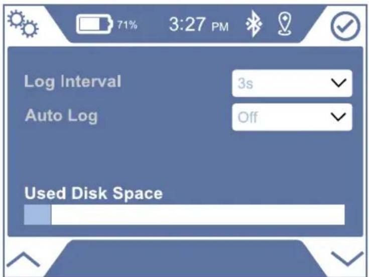
Log Interval
Choose how often the device should capture ppm readings in the log.
Auto log
Allows the user to either automatically begin logging on startup or to enable a prompt on startup to begin logging.
7.7 Connectivity Settings
This menu allows you to enable or disable Bluetooth or GPS.
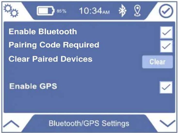
Pairing Code Required
When enabled, a code will be displayed on both the D-TEK Pro display and the D-TEK Pro App to confirm you are pairing to the correct device.
Clear Paired Devices
Select this option to clear all paired devices in D-TEK Pro's memory.
8 App
Download the free D-TEK Pro app for your smartphone or tablet for additional functions.

The D-TEK Pro app allows you to:
• View real-time data on the app
- Save and share job logs including pictures, GPS pin, and customer information
- Update D-TEK Pro software
The app is available for download on the App Store ^® or on Google Play ^™ .
9 Accessories
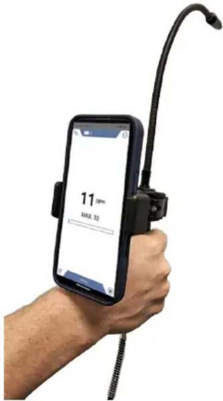
Phone Mount
D-TEK Pro includes a phone mount that can mount your phone directly to the handpiece. This allows you to use your phone as an additional display to see real-time data while leak checking.
Soft Case with Shoulder Strap
This included accessory provides additional protection and allows you to easily carry D-TEK Pro while leak checking and climbing up and down ladders.
Leak Detection Pro Kit
D-TEK Pro is compatible with all parts included in the INFICON Leak Detection Pro Kit (part number 724-712-G1), sold separately.
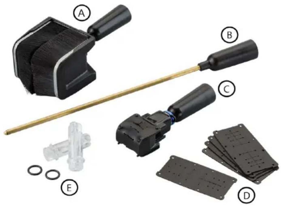
| Reference Description | |
| A I-Tip XL | |
| B Needle probe | |
| C I-Tip | |
| D Rubber refills | |
| E Spare filters |
Needle probe extension - Allows for leak checking in tight spots and insulation. This probe is pointed to easily puncture or split underneath insulation and fit into small areas.
I-Tip and I-Tip XL - Isolates the leak to a smaller volume and eliminates wind. Allows for leak checking around pipes and tubing in windy environments. Also allows for leak checking joints behind pipes.
To install the needle probe extension, I-Tip, or I-Tip XL:
1 Unscrew the probe tip. Leave the filter in place on the probe.
2 Place the accessory over the filter.
3 Screw the accessory onto the probe. Do not overtighten.
NOTICE
Important!
Do not use D-TEK Pro without a filter. Use without a filter can damage the sensor.
10 Maintenance
D-TEK Pro does not contain user serviceable sensors or battery. The only user serviceable parts are described in the section below.
Replacing Filters
D-TEK Pro uses two filter types in order to keep the internals clean. Do not use D-TEK Pro without both clean filters in place.
Probe Filter
Unscrew the probe tip and examine the white cloth to determine if the filter needs to be changed. If the cloth appears discolored, install a new filter. Changing the filter is also an easy troubleshooting step if you suspect your leak detector is not properly detecting refrigerants. A clogged air filter can limit the sample air flow.
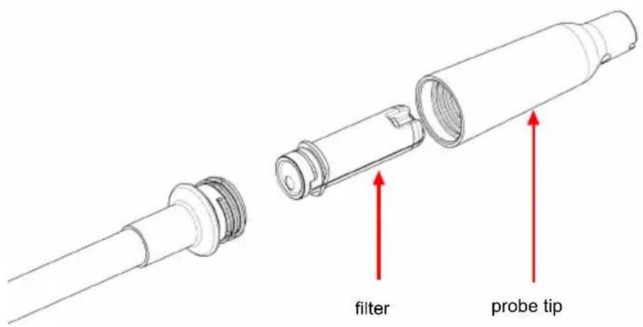

Exposing the filter to water or oil can block air flow. If this occurs, first disconnect the disc filter to release any vacuum in the sample tube. Then remove the filter with the unit turned off and the probe facing down to avoid getting contaminants in the probe and install a new filter. If the filter is wet, it can be reused once it dries.

CAUTION
Never use the instrument without a probe tip and filter.
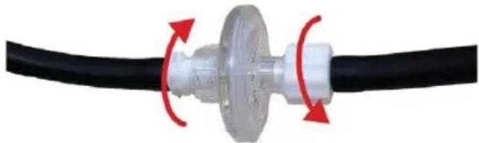
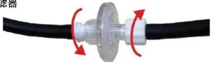
Disc Filter
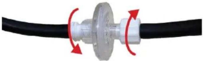
To replace the disc filter, unscrew the plastic fitting on each side of the disc and screw in the new filter. Do not overtighten.
Remove old filter
natural_image
Close-up of a black cable with a metallic connector and red circular arrows indicating rotation or movement (no text or symbols)Install new filter
natural_image
Close-up of a black cable with a metallic connector and red circular arrows indicating rotation (no text or symbols)Replacing the Probe
D-TEK Pro has a replaceable probe and is also compatible with the optional Extra-Long Probe accessory (part number 721-611-G1) for hard-to-reach areas.
To change the probe:
1 Inspect the area around the base of the probe for debris to ensure nothing will fall into the tube. Clean if necessary.
2 Unscrew the probe from the D-TEK Pro probe handle using a 10 mm wrench.
3 Screw on the new probe to approximately 35 in·lb (4 N·m). Do not overtighten.
4 Unscrew the probe tip from the old probe and remove the filter (or use a new one).
5 Insert the filter into the new probe.
6 Screw the probe tip onto the new probe. Do not overtighten.

CAUTION
Always remove the probe with a 10 mm wrench at the base of the probe.
Unscrewing the probe in any way other than the specified method can cause damage to the probe.
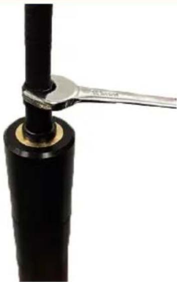
natural_image
Close-up of a black cylindrical object with a metallic tool extending from its tip, against a white background (no text or symbols visible)11 Cleaning and Storage
D-TEK Pro can be cleaned with mild detergent or isopropyl alcohol. Care should be taken to prevent cleaner from entering the probe, tubing, or inlet. Do not clean with gasoline, acetone, or other aggressive solvents as they may damage the plastic or display.
12 Replacement Parts and Accessories
| Replacement hose/hand probe assembly | 508-700-G1 |
| Replacement probe 724-703-G1 | |
| Extra-long probe 721-611-G1 | |
| Replacement probe cap 712-705-G1 | |
| Spare probe filters 712-707-G1 | |
| Spare disc filters 508-701-G1 | |
| Phone holder 508-702-P1 | |
| Shoulder strap 508-703-P1 | |
| Replacement wall charger 508-704-P1 | |
| Needle probe extension 721-612-G1 | |
| Leak detection pro kit 724-712-G1 |
13 Troubleshooting Guide
| Problem Cause Remedy | ||
| The status LED illuminates red. | An internal error has occurred. This can be caused by a failed battery. | Contact INFICON or your local distributor for service. |
Sensor error or the following symbol is displayed: | A sensor error has occurred. This may indicate the sensor has been contaminated or has reached end of life. | Contact INFICON or your local distributor for service. |
| The display does not turn on after long-pressing the power button. | The battery level is critically low. | Charge the battery. |
| The unit turns on, but does not detect refrigerant. | The filter is clogged, restricting the air flow. | Replace the filter cartridge and/or disc filter. See Replacing Filters. |
| The pump has failed. Listen for the pump sound. If the pump is not making a sound and the battery has a proper charge, contact INFICON. | ||
| The reference sample is contaminated. | Let run in clean air for up to five minutes. | |
| The ppm falls to zero in an area known to be contaminated. | The reference sample may be contaminated. | Let run in clean air for several minutes. |
| The pump is not making a sound. | The pump has failed. If the battery has a proper charge, contact INFICON. | |
| Error message "Flow error - Ensure hose and filters are in place" is displayed. | Flow rate is too high. Filters or hose may have been removed or hose may be leaking or damaged. | Ensure all hoses and filters are in place and connections are tight. Check hose for damage and replace if damaged. |
| Error message "Flow error - Check filters and probe tip for debris" is displayed. | Flow rate is too low. Filters or probe tip may be clogged. | Check filters and replace if dirty or wet. Check probe tip for debris and clean if necessary. |
14 Warranty and Liability-Limitation
INFICON warrants your instrument to be free from defects of materials or workmanship for one or two years (depending on region) from the date of purchase. INFICON does not warrant items that deteriorate under normal use, including batteries, sensors, and filters. In addition, INFICON does not warrant any instrument that has been subjected to misuse, negligence, or accident, or has been repaired or altered by anyone other than INFICON. INFICON liability is limited to instruments returned to INFICON, transportation prepaid, not later than thirty (30) days after the warranty period expires, and which INFICON judges to have malfunctioned because of defective materials or workmanship. INFICON liability is limited to, at its option, repairing or replacing the defective instrument or part. This warranty is in lieu of all other warranties, express or implied, whether of MERCHANTABILITY or of FITNESS FOR A PARTICULAR PURPOSE or otherwise. All such other warranties are expressly disclaimed. INFICON shall have no liability in excess of the price paid to INFICON for the instrument plus return transportation charges prepaid. INFICON shall have no liability for any incidental or consequential damages. All such liabilities are EXCLUDED.
15 Returning the Instrument for Warranty or Repair
Contact your wholesaler for warranty evaluation or out-of-warranty repair. Do not return the unit to INFICON directly. All instruments and parts returned to INFICON for repair or credit must be properly packaged, insured, shipped transportation charges prepaid, and must have a Return Material Authorization (RMA) number issued before the material is returned. The RMA number must be marked on all shipping labels and packing slips. Please see your INFICON distributor for assistance. If you have any questions, contact INFICON at 800-344-3304, or contact your local INFICON sales office.
Índice
natural_image
Close-up of a blue industrial electrical connector with metallic connectors and a cable, showing red arrows pointing to the connector (no text or symbols visible)natural_image
Close-up of a black cable with metallic connectors and a red rotation arrow indicating cable attachment (no text or symbols visible)Intervalo de registro
natural_image
Close-up of a black cylindrical object with a metallic tool inserted, no visible text or symbolsnatural_image
Close-up of a metallic connector with two connectors inserted, showing red arrows indicating connection points (no text or symbols visible)natural_image
Close-up of a black cable with metallic connectors and a red arrow indicating rotation (no text or symbols)Protokollintervall
natural_image
Close-up of a black cylindrical object with a metallic wrench extending from its tip (no text or symbols visible)natural_image
Close-up of a metallic connector with two brass connectors inserted into a blue panel, connected to a black cable (no text or symbols visible)natural_image
Close-up of a black cable with metallic connectors and a red arrow indicating rotation (no text or symbols)7.5 Aria fresca zero
natural_image
Close-up of a black cylindrical object with a metallic wrench extending from its tip (no text or symbols visible)D-TEK Pro uses the display screen for nearly all indicators and information. The display consists of a top bar, main display, and a bottom bar. Symbols displayed in each of the 4 corners indicate the current function of the corresponding button.
natural_image
Close-up of a blue audio connector with multiple metallic and gold connectors connected to a black cable, showing red arrows indicating connection points (no text or symbols visible)natural_image
Close-up of a black cable with metallic connectors and brass fittings, attached to a blue panel (no text or symbols visible)natural_image
Close-up of a black cylindrical object with a metallic wrench extending from its side (no text or symbols visible)natural_image
Close-up of a blue audio jack connector with two metallic connectors and a black cable inserted, showing red arrows pointing to the connector (no text or symbols visible)natural_image
Close-up of a black cable with metallic connectors and a red arrow indicating rotation (no text or symbols)機器の電源投入と使用準備
ログ間隔
ペアリングコードが必要です
natural_image
Close-up of a black cylindrical object with a metallic wrench extending from its tip (no text or symbols visible)11 清掃と保管
记录间隔
需要配对码
D-TEK Pro 应用程序允许您:
natural_image
Close-up of a black cable with a metallic connector and red circular arrows indicating rotation (no text or symbols)安装新过滤器
natural_image
Close-up of a black cable with a metallic connector and red directional arrows indicating rotation (no text or symbols)更换探头
natural_image
Close-up of a black cylindrical object with a metallic tool inserted, no visible text or symbols11 清洁和储存
©2025 All rights reserved.
로그 간격
페어링 코드 필요
natural_image
Close-up of a black cylindrical object with a metallic tool extending from its tip, against a white background (no text or symbols visible)11 청소 및 보관
Two Technology Place
East Syracuse, NY 13057-9714 USA
Phone:+1.800.344.3304
Email:service.tools@inficon.com
www.inficonservicetools.com
Bonner Strasse 498
D-50968 Cologne, Germany
Phone: +49 221 56788-660
Email:servicetools.europe@inficon.com
www.inficonservicetools-europe.com
Section A, Building 6
108 Shuya Road, Shanghai, China
Phone:+86-21-62093094
Email:reach.china@inficon.com
INFICON AB
Box 76
58 102 Linköping, Sweden
Due to our continuing program of product improvements, specifications are subject to change without notice.
All trademarks are the property of their respective owners.
©2025 INFICON 074-839-P16-A
Korea
Phone:+82-31-206-2890
Email:reach.korea@inficon.com
Japan
Phone:+81-44-322-8901
Email: reach.japan@inficon.com
Singapore
Phone:+65-6631-0303
Email: reach.singapore@inficon.com
Taiwan
Phone:+886-3-5525828
Email: reach.taiwan@inficon.com
- D-TEK PRO
- Table of Contents
- Disclaimer and Copyright
- Disclaimer
- Copyright
- Cautions and Warnings
- Cautions:
- WARNING
- Specifications
- Patents
- What is Cloud Hunting?
- D-TEK Pro
- Screen Layout and Symbols
- Operation
- Getting Started
- Charging the Battery
- Connecting the Sampling Hose and Probe Assembly
- CAUTION
- Turning On the Instrument and Preparing for Use
- i
- Home Screen
- Checking for Leaks
- Cloud Hunting
- Pinpointing Leaks
- Settings Menu
- Fresh Air Zero
- Data Log Settings
- Log Interval
- Auto log
- Connectivity Settings
- Pairing Code Required
- Clear Paired Devices
- App
- Accessories
- Phone Mount
- Soft Case with Shoulder Strap
- Leak Detection Pro Kit
- NOTICE
- Important!
- Maintenance
- Replacing Filters
- Probe Filter
- Disc Filter
- Replacing the Probe
- Cleaning and Storage
- Replacement Parts and Accessories
- Troubleshooting Guide
- Warranty and Liability-Limitation
- Returning the Instrument for Warranty or Repair
- Índice
- Aria fresca zero
- 機器の電源投入と使用準備
- ログ間隔
- 清掃と保管
- 更换探头
- 清洁和储存
- 청소 및 보관
Brand : INFICON
Model : D-TEK Pro
Category : Measuring equipment