
GGC 18V-12 Professional - Drill BOSCH - Free user manual and instructions
Find the device manual for free GGC 18V-12 Professional BOSCH in PDF.

| Product type | Cordless threaded rod cutter |
| Brand | Bosch |
| Model | GGC 18V-12 Professional |
| Rated voltage | 18 V |
| Cutting capacity - Mild steel | M6, M8, M10, M12 |
| Cutting capacity - Stainless steel | M6, M8, M10 |
| Dimensions (L x W x H) | 221 x 133 x 272 mm |
| Weight (without battery) | 3.4 kg |
| Charging ambient temperature | 0 °C to +35 °C |
| Operating and storage ambient temperature | -20 °C to +50 °C |
| Sound pressure level | 83 dB(A) |
| Sound power level | 91 dB(A) |
| Uncertainty K (sound) | 3 dB |
| Vibration emission value (a_h) | 1.1 m/s² |
| Uncertainty K (vibration) | 1.5 m/s² |
| Compatible batteries | GBA 18V..., ProCORE18V..., EXPERT18V..., EXBA18V..., CORE18V... |
| Recommended chargers | GAL18..., GAL 36..., GAL 12V/18..., GAX 18..., EXAL18... |
| Main functions | Cutting threaded rods, mode selector (cut/lock/reverse), adjustable depth stop, threaded rod guide, LED light, suspension hook, preparation for fall protection |
| Safety | Overload protection, overheat protection, double battery lock, automatic stop at end of cycle |
| Maintenance and cleaning | Clean ventilation openings with a soft brush, replace cutting dies in pairs, remove burrs from dies |
| Spare parts and repairability | Cutting dies (reference see manual), die screws, hex key, fall protection bracket; repair by Bosch after-sales service |
| General information | Professional cordless tool designed to cut threaded rods up to M12 in mild steel and M10 in stainless steel |
Frequently Asked Questions - GGC 18V-12 Professional BOSCH
User questions about GGC 18V-12 Professional BOSCH
0 question about this device. Answer the ones you know or ask your own.
Ask a new question about this device
Download the instructions for your Drill in PDF format for free! Find your manual GGC 18V-12 Professional - BOSCH and take your electronic device back in hand. On this page are published all the documents necessary for the use of your device. GGC 18V-12 Professional by BOSCH.
USER MANUAL GGC 18V-12 Professional BOSCH
natural_image
3D rendered mechanical device with articulated arm and base mount (no visible text or symbols)natural_image
3D rendering of a mechanical device with labeled part (17), no visible text or symbols on the device itself4
A
B
C
E
F
natural_image
Four-panel illustration showing different types of cable or wire components, no text or symbols present6
8
Deutsch
Sicherheitshinweise
General Power Tool Safety Warnings
WARNING
Read all safety warnings, instructions, illustrations and specifica-
tions provided with this power tool. Failure to follow all instructions listed below may result in electric shock, fire and/or serious injury.
Save all warnings and instructions for future reference.
The term "power tool" in the warnings refers to your mains-operated (corded) power tool or battery-operated (cordless) power tool.
Work area safety
▶ Keep work area clean and well lit. Cluttered or dark areas invite accidents.
▶ Do not operate power tools in explosive atmospheres, such as in the presence of flammable liquids, gases or dust. Power tools create sparks which may ignite the dust or fumes.
▶ Keep children and bystanders away while operating a power tool. Distractions can cause you to lose control.
Electrical safety
▶ Do not expose power tools to rain or wet conditions. Water entering a power tool will increase the risk of electric shock.
Personal safety
▶ Stay alert, watch what you are doing and use common sense when operating a power tool. Do not use a power tool while you are tired or under the influence of drugs, alcohol or medication. A moment of inattention while operating power tools may result in serious personal injury.
▶ Use personal protective equipment. Always wear eye protection. Protective equipment such as a dust mask, non-skid safety shoes, hard hat or hearing protection used for appropriate conditions will reduce personal injuries.
▶ Prevent unintentional starting. Ensure the switch is in the off-position before connecting to power source and/or battery pack, picking up or carrying the tool.
Carrying power tools with your finger on the switch or energising power tools that have the switch on invites accidents.
Remove any adjusting key or wrench before turning the power tool on. A wrench or a key left attached to a rotating part of the power tool may result in personal injury.
▶ Do not overreach. Keep proper footing and balance at all times. This enables better control of the power tool in unexpected situations.
▶ Dress properly. Do not wear loose clothing or jewellery. Keep your hair and clothing away from moving parts. Loose clothes, jewellery or long hair can be caught in moving parts.
If devices are provided for the connection of dust extraction and collection facilities, ensure these are connected and properly used. Use of dust collection can reduce dust-related hazards.
▶ Do not let familiarity gained from frequent use of tools allow you to become complacent and ignore tool safety principles. A careless action can cause severe injury within a fraction of a second.
Power tool use and care
▶ Do not force the power tool. Use the correct power tool for your application. The correct power tool will do the job better and safer at the rate for which it was designed.
▶ Do not use the power tool if the switch does not turn it on and off. Any power tool that cannot be controlled with the switch is dangerous and must be repaired.
▶ Disconnect the plug from the power source and/or remove the battery pack, if detachable, from the power tool before making any adjustments, changing accessories, or storing power tools. Such preventive safety measures reduce the risk of starting the power tool accidentally.
▶ Store idle power tools out of the reach of children and do not allow persons unfamiliar with the power tool or these instructions to operate the power tool. Power tools are dangerous in the hands of untrained users.
- Maintain power tools and accessories. Check for misalignment or binding of moving parts, breakage of parts and any other condition that may affect the power tool's operation. If damaged, have the power tool repaired before use. Many accidents are caused by poorly maintained power tools.
▶ Keep cutting tools sharp and clean. Properly maintained cutting tools with sharp cutting edges are less likely to bind and are easier to control.
▶ Use the power tool, accessories and tool bits etc. in accordance with these instructions, taking into account the working conditions and the work to be performed. Use of the power tool for operations different from those intended could result in a hazardous situation.
▶ Keep handles and grasping surfaces dry, clean and free from oil and grease. Slippery handles and grasping surfaces do not allow for safe handling and control of the tool in unexpected situations.
Battery tool use and care
▶ Recharge only with the charger specified by the manufacturer. A charger that is suitable for one type of battery pack may create a risk of fire when used with another battery pack.
▶ Use power tools only with specifically designated battery packs. Use of any other battery packs may create a risk of injury and fire.
When battery pack is not in use, keep it away from other metal objects, like paper clips, coins, keys, nails, screws or other small metal objects, that can make a connection from one terminal to another. Shorting the battery terminals together may cause burns or a fire.
▶ Under abusive conditions, liquid may be ejected from the battery; avoid contact. If contact accidentally occurs, flush with water. If liquid contacts eyes, additionally seek medical help. Liquid ejected from the battery may cause irritation or burns.
▶ Do not use a battery pack or tool that is damaged or modified. Damaged or modified batteries may exhibit unpredictable behaviour resulting in fire, explosion or risk of injury.
▶ Do not expose a battery pack or tool to fire or excessive temperature. Exposure to fire or temperature above 130 °C may cause explosion.
▶ Follow all charging instructions and do not charge the battery pack or tool outside the temperature range specified in the instructions. Charging improperly or at temperatures outside the specified range may damage the battery and increase the risk of fire.
Service
▶ Have your power tool serviced by a qualified repair person using only identical replacement parts. This will ensure that the safety of the power tool is maintained.
▶ Never service damaged battery packs. Service of battery packs should only be performed by the manufacturer or authorized service providers.
Safety instructions for hand-held tools used at height
When using the tool at height, follow the tool manufacturer's recommendations for tethering the tool and for accessories to be used at height. Use of non-recommended tethering methods or accessories may increase the risk of a drop from height, which may result in serious injury to bystanders below.
When using the tool at height, do not install an accessory on the tool that would cause the attachment point kg (lb(s)) rating to be exceeded. If the mass of the tool, battery, attachments and accessory exceeds the maximum rating of the attachment point, it may fail during a drop from height, which may result in serious injury to bystanders below.
Safety Instructions for Threaded Rod Cutters

Wear safety goggles. This will protect your eyes against little pieces of the material splintering off.
Keep your hands away from the cutting jaws and moving parts. Fingers can be caught by the cutting mechanism which can lead to serious injuries.
▶ Keep your face away from the cutting mechanism. Fragments of the threaded rod may be thrown out during cutting which can lead to injuries.
▶ Do not machine live material, and hold the power tool by the insulated gripping surfaces. Contact with live material may make metal parts of the tool live, posing a risk of electric shock.
▶ Wear gloves when machining threaded rods. The edges and chips of the workpiece are sharp and may still be hot immediately after machining.
20 | English
▶ Secure the workpiece. A workpiece clamped with clamping devices or in a vice is held more secure than by hand.
To safely cut long or large threaded rods, the power tool can be positioned on a horizontal surface using the supporting surfaces. It must not be clamped into a vice or fastened to a workbench.
▶ Do not place the power tool on the chips of the workpiece. This may damage the power tool and cause it to malfunction.
▶ Always ensure that you have a stable footing, especially when working in an elevated position. Hold the threaded rod during and after cutting to prevent the cut-off threaded rod from falling down. A cut-off threaded rod can cause serious personal injury.
If you are working in an elevated position, secure the power tool sufficiently using a fall protection system and ensure that there are no persons below the work area. Wear protective headgear when carrying out overhead work. This will enable you to avoid material damage and personal injury if you inadvertently drop the power tool.
In case of damage and improper use of the battery, vapours may be emitted. The battery can set alight or explode. Ensure the area is well ventilated and seek medical attention should you experience any adverse effects. The vapours may irritate the respiratory system.
▶ Do not modify or open the battery. There is a risk of short-circuiting.
The battery can be damaged by pointed objects such as nails or screwdrivers or by force applied externally. An internal short circuit may occur, causing the battery to burn, smoke, explode or overheat.
▶ Only use the battery in the manufacturer's products. This is the only way in which you can protect the battery against dangerous overload.

Protect the battery against heat, e.g. against continuous intense sunlight, fire, dirt, water and moisture. There is a risk of explosion and short-circuiting.
Product Description and Specifications

Read all the safety and general instructions. Failure to observe the safety and general instructions may result in electric shock, fire and/or serious injury.
Please observe the illustrations at the beginning of this operating manual.
Intended Use
The power tool is intended for cutting threaded rods.
Product Features
The numbering of the product features refers to the diagram of the power tool on the graphics page.
(1) Front view
(2) Moving holder
(3) Cutting jaw (2 x)
(4) Stationary holder
(5) Threaded rod guide
(6) Rechargeable battery ^a)
(7) Battery release button ^a)
(8) Hex key
(9) Button for adjusting the depth stop
10) Depth stop
(11) Depth stop reference surface
(12) Supporting surface (3 x)
(13) Selector switch (cutting, locked, opening)
(14) Release switch
(15) Utility hook
(16) Worklight
(17) Handle (insulated gripping surface)
(18) Screws for cutting jaws (2 x)
(19) Cutting line
(20) Threaded rod ^b)
(21) Attachment area for the fall protection system on the power tool
(22) Fall protection system ^b)
(23) Fall protection system anchorage point fixer ^b)
a) This accessory is not part of the standard scope of delivery.
b) Commercially available (not included in the scope of delivery)
Technical Data
| Threaded rod cutter GGC 18V-12 | |
| Article number | 3 601 JM8 0.. |
| Rated voltage V= 18 | |
| Cutting capacity | |
| - Soft steel M 6 x 1 | M 8 x 1.25M 10 x 1.5M 12 x 1.75 |
| - Stainless steel M 6 x 1 | M 8 x 1.25M 10 x 1.5 |
| Dimensions (L x W x H) mm 221 x 133 x 272 | |
| Weight ^A) | kg 3.4 |
| Recommended ambient temperature during charging | °C 0 to +35 |
Threaded rod cutter GGC 18V-12
| Permitted ambient temperature during operation ^B) and during storage | °C -20 to +50 |
| Compatible rechargeable batteries | GBA18V...GBA 18V...ProCORE18V...EXPERT18V...EXBA18V...CORE18V... |
| Recommended battery chargers | GAL18...GAL 18...GAL 36...GAL12V/18...GAL 12V/18...GAX 18...EXAL18... |
A) Without rechargeable battery (you can find the battery weight at www.bosch-professional.com.)
B) Limited performance at temperatures < 0 °C
Values can vary depending on the product, scope of application and environmental conditions. To find out more, visit www.bosch-professional.com/wac.
Noise/Vibration Information
Noise emission values determined according to EN 62841-1.
Typically, the A-weighted noise level of the power tool is: Sound pressure level 83 dB(A); sound power level 91 dB(A). Uncertainty K = 3 dB.
Wear hearing protection!
Vibration values a_h (continuous vibrations), p_F (repeated shock vibrations) and uncertainty K determined according to EN 62841-1:
$$ a _ {n} = 1. 1 \mathrm{m} / \mathrm{s} ^ {2}, K = 1. 5 \mathrm{m} / \mathrm{s} ^ {2}, p _ {F} = 2 1 0 \mathrm{m} / \mathrm{s} ^ {2} (K = 1 3 \mathrm{m} / \mathrm{s} ^ {2}) $$
The vibration level and noise emission value given in these instructions have been measured in accordance with a standardised measuring procedure and may be used to compare power tools. They may also be used for a preliminary estimation of vibration and noise emissions.
The stated vibration level and noise emission value represent the main applications of the power tool. However, if the power tool is used for other applications, with different accessories or is poorly maintained, the vibration level and noise emission value may differ. This may significantly increase the vibration and noise emissions over the total working period.
To estimate vibration and noise emissions accurately, the times when the tool is switched off or when it is running but not actually being used should also be taken into account. This may significantly reduce vibration and noise emissions over the total working period.
Implement additional safety measures to protect the operator from the effects of vibration, such as servicing the power tool and accessories, keeping their hands warm, and organising workflows correctly.
Overload protection
In normal conditions of use, the power tool cannot be overloaded. In the event of excessive load or temperatures outside of the permitted battery temperature range, it will automatically switch off. Then switch off the power tool and stop the work that caused the power tool to be overloaded. Switch the power tool back on to restart the work process.
Note: The overload protection is activated if you try cutting the following types of threaded rods.
- A threaded rod that is larger than the size of the cutting jaws.
- A threaded rod that has a higher strength than the cutting capacity of the power tool.
Overheating protection
If the power tool overheats, it will switch off automatically. Allow the power tool to cool down before switching it on again.
Rechargeable battery
Bosch sells some cordless power tools without a rechargeable battery. You can tell whether a rechargeable battery is included with the power tool by looking at the packaging.
Charging the battery
▶ Use only the chargers listed in the technical data. Only these chargers are matched to the lithium-ion battery of your power tool.
Note: Lithium-ion rechargeable batteries are supplied partially charged according to international transport regulations. To ensure full rechargeable battery capacity, fully charge the rechargeable battery before using your tool for the first time.
Inserting the Battery
Push the charged battery into the battery holder until it clicks into place.
Removing the Battery
To remove the rechargeable battery, press the battery release button and pull the battery out. Do not use force to do this.
The rechargeable battery has two locking levels to prevent the battery from falling out if the battery release button is pressed unintentionally. The rechargeable battery is held in place by a spring when fitted in the power tool.
Battery charge indicator
Note: Not all battery types have a battery charge indicator. The green LEDs on the battery charge indicator indicate the state of charge of the battery. For safety reasons, it is only possible to check the state of charge when the power tool is not in operation.
22 | English
Press the button for the battery charge indicator or to show the state of charge. This is also possible when the battery is removed.
If no LED lights up after pressing the button for the battery charge indicator, then the battery is defective and must be replaced.
Rechargeable battery type GBA 18V... | GBA18V...

LED Capacity
| 3× continuous green light 60–100% |
| 2× continuous green light 30–60% |
| 1× continuous green light 5–30% |
| 1× flashing green light 0–5% |
Battery model ProCORE18V... | EXPERT18V... | EXBA18V... | CORE18V...

LED Capacity
| 5 × continuous green light 80-100 % |
| 4 × continuous green light 60-80 % |
| 3 × continuous green light 40-60 % |
| 2 × continuous green light 20-40 % |
| 1 × continuous green light 5-20 % |
| 1 × flashing green light 0-5 % |
Battery defect risk detection
EXPERT18V... | EXBA18V...
In addition to the state of charge of the rechargeable battery, the LEDs on the battery charge indicator can also indicate the risk of a battery defect.
To activate the function, press and hold the button for the battery charge indicator for 3 seconds. The analysis of the battery is signalled by a moving light on the battery charge indicator. The result of is shown on the battery charge indicator.
1 LED: The rechargeable battery has a high defect risk. Performance and runtime may
already be reduced. Replacing the rechargeable battery is recommended.

5 LEDs: The rechargeable battery is in good condition and has a low defect risk.
Please note: The rechargeable battery defect risk assessment works in a binary manner and offers a simplified status assessment, indicating either that the rechargeable battery is in good condition or that the rechargeable battery has an increased defect risk. A percentage of the battery status is not shown.
Recommendations for Optimal Handling of the Battery
Protect the battery against moisture and water.
Only store the battery within a temperature range of -20 to 50 °C. Do not leave the battery in your car in the summer, for example.
Occasionally clean the ventilation slots on the battery using a soft brush that is clean and dry.
A significantly reduced operating time after charging indicates that the battery has deteriorated and must be replaced.
Follow the instructions on correct disposal.
Assembly
Before carrying out any work on the power tool (e.g. maintenance, tool change etc.), remove the battery from the power tool. There is risk of injury from unintentionally pressing the on/off switch.
▶ Before inserting the rechargeable battery into the power tool, always ensure that the release switch (14) is working properly and returns to the OFF position when it is released.
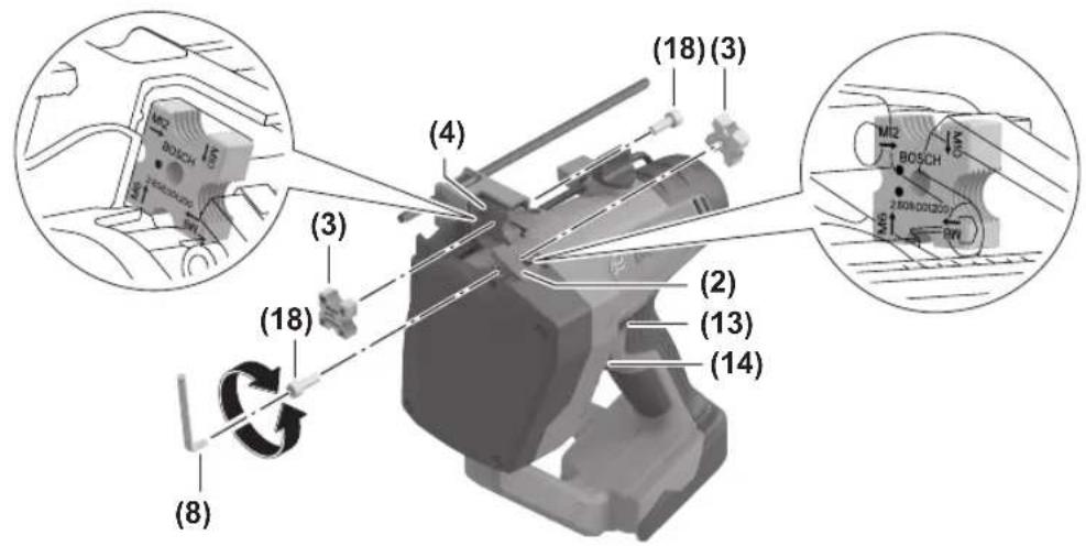
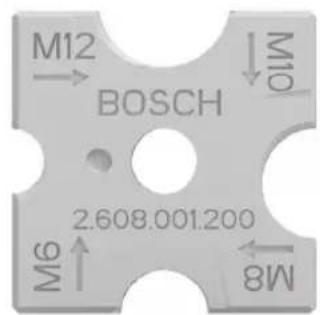
Fitting the Cutting Jaws (see figures A–E)
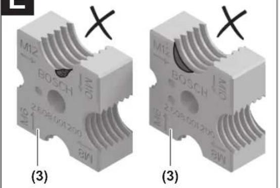
Always fit the cutting jaws (3) in the correct orientation and make sure they are properly secured. If the cutting jaws are not attached correctly or they are attached loosely, this could cause a break in the cutting jaws, which could lead to personal injury from fragments being flung out (see figure A).
Remove any burrs from the cutting jaws with a file (3).
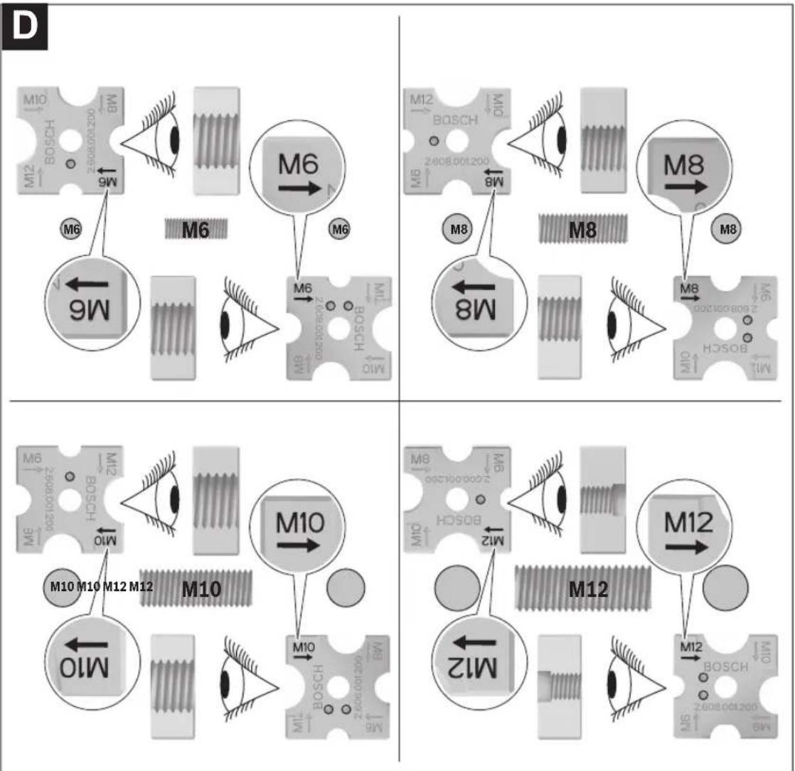
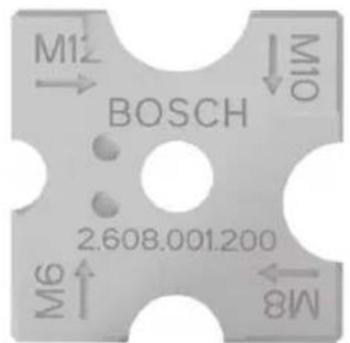
Always use a pair of cutting jaws (3). This consists of one cutting jaw marked with a dot and one cutting jaw marked with two dots (see figure D). The pair of cutting jaws can be replaced between the moving holder (2) and the stationary holder (4).
Check whether the holders (2) and (4) for the cutting jaws (3) are fully open. If this is not the case, insert the rechargeable battery and press the release switch (14) until the holders are fully open. Remove the battery again.
Set the selector switch (13) to the locking position Ⓤ (see figure C).
Unscrew the screws (18) using the hex key (8) provided. Insert the cutting jaws (3) into the holders (2) and (4) in the correct position. Secure the cutting jaws (3) again with the screws (18).
Note: The pair of cutting jaws (3) can only be screwed together in the power tool if the labelled end surfaces are facing each other. The cutting jaws must be oriented according to the thread size to be cut (see figure D).
Operation
▶ Replace the cutting jaws (3) if the cutting edges are chipped or deformed (see figure E). Refer to the fur-
ther instructions (see "Replacing the Cutting Jaws", page 25).
The cutting jaws (3) are extremely sharp. You should therefore always keep your hands away from cutting edges and moving parts. Do not cut short workpiece parts where your hands could get close to the cutting jaws. There is a risk of serious injury or of limbs being severed.
▶ Make sure that cutting jaws (3) of the correct size are fitted to the power tool and that both cutting jaws are oriented in the correct position. Before you start cutting, check the thread size printed on the cutting jaws.
▶ Before pressing the release switch (14), insert the threaded rod such that its screw threads match those of the stationary cutting jaw. If the screw threads are not aligned correctly, this could cause a break in the cutting jaws and cause personal injury from fragments being flung out.
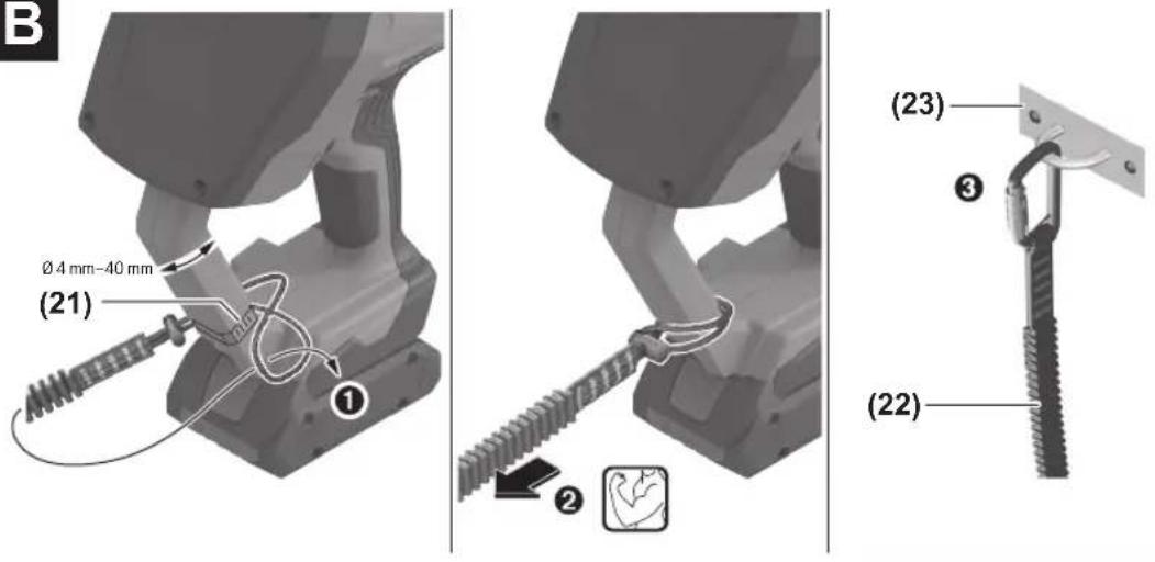
Use with a Fall Protection System
▶ Safety instructions for use in a raised working position. Read all the safety and general instructions. Failure to comply with advice and instructions can result in serious injuries.
▶ Read all safety and general instructions for the fall protection system (22) and the fall arrest system. Failure to comply with advice and instructions can result in serious injuries.
▶ Always use a fall protection system when working at heights of 1.1 m and above.
▶ Only secure the tool to fixed, stable attachment points (e.g. scaffolding struts). Unsecured objects such as ladders, toolboxes, etc. cannot prevent falling. The load capacity of the attachment point must be equal to or higher than the load capacity of the attachment area for the fall protection system on the power tool.
Load capacity of the attachment area for 6 kg (13.2 lbs) the fall protection system on the power tool ^4)
Maximum length of fall protection system 1.1 m (3.6 ft)
A) This includes the power tool including all attachments and accessories.
Fitting the Fall Protection System (see figure B)
To use the fall protection system, secure the fall protection system (22) to the attachment area for the fall protection system on the power tool (21). For fall protection systems with a loop, wrap around the attachment area as shown in the figure B. Pull the loop and ensure that the loop is not twisted in itself.
Instructions for use
- The fall arrest system is intended for use by qualified and skilled individuals.
-
Only secure the fall protection system by the provided attachment area of the fall protection system on the power tool.
-
Do not use any other parts of the power tool to secure the fall protection system and do not modify the power tool in order to create attachment areas.
- Only use fall protection systems with an equal or higher load capacity than the above-listed load capacity of the attachment area of the fall protection system on the power tool.
- Only use fall protection systems with a looped end or carabiners.
- Preferably use a fall protection system with shock absorption.
- Only use fall protection systems according to ANSI ISEA 121:2018. Do not use any ropes, lines, steel ropes or cables as fall protection systems.
- Before starting work in a raised position, ensure that the fall protection system is properly attached at both ends.
- Do not use the fall protection system in any way that restricts the protective covers, switches and locking mechanisms in their regular functioning.
- Do not use more than one tool per fall protection system.
- Use the fall arrest system such that the power tool does not move away from the user when it falls down. Falling power tools swing into the fall arrest system. This can lead to injury or a loss of balance.
- Do not extend shock-absorbing fall protection systems during use. Only use fall protection systems in an unextended state.
- Do not use the fall protection system to lift the power tool or to pull it up.
- Do not use the fall protection system to secure persons.
- Do not replace accessories in a raised working position.
- Only use accessories that are intended for working in a raised position and which are specified in these operating instructions.
- Keep the fall protection system away from high-voltage areas or electricity cables. Otherwise, there is a risk of an electric shock.
- Do not modify the attachment area of the fall protection system on the power tool and do not use it in any other way than that described in these operating instructions.
- Do not use the fall arrest system in the vicinity of moving parts. The fall protection system could become caught, which may lead to crushing.
- Keep the fall protection system away from sharp edges, cutting edges, chips, sparks and other elements that may cause damage.
- Avoid becoming entangled in the fall protection system.
- Do not carry the power tool by the fall protection system or the attachment area of the fall protection system.
- Only switch the power tool from one hand to the other when you are on a secure footing.
- Do not attempt to catch a falling power tool.
- Inspect the attachment area of the fall protection system and the fall protection system before every use and after the power tool has fallen to ensure that it is working properly. Do not use the power tool or the fall protection sys-
24 | English
tem in the event of damage (cracks, damage to the seams, etc.) or if it is not working properly. Damage to the attachment area of the fall protection system includes, among other damage, stress whitening on plastic parts, cracks, breaks and deformation.
- If the power tool has fallen from height into the fall arrest system, it must be labelled and taken out of active operation.
- If you use a fall protection system with a triggering indicator and the triggering indicator is visible, this is also no longer operational.
Starting Operation
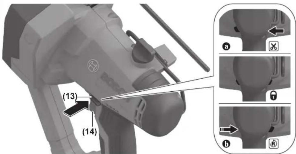
Selector Switch (see figure C)
▶ Always set the selector switch (13) to the locking position when you are not using the power tool.
▶ Before starting to operate the power tool, always ensure that the selector switch (13) is in the correct position.
▶ Do not move the selector switch (13) when the release switch (14) is pressed. This may damage the power tool.
To start cutting mode, set the (13) selector switch to the cutting position (position a, and press the release switch (14). To reverse the direction of movement, set the selector switch (13) to the reversal position (position b) and press and hold the selector switch in this position while pressing the release switch. When you release the selector switch and the release switch, the power tool will automatically switch to the locking position. If you press the release switch (14) continuously, the power tool will go through a full cycle and automatically stop in the fully open position. To lock the release switch (14), set the selector switch (13) to the locking position. When in this position, the release switch (14) cannot be pressed.
Note: Do not cut threaded rods while the direction of movement is reversed. This will lead to the power tool being damaged. Only operate the power tool in the reverse direction of movement with no load or in order to fully open the cutting jaws (3).
Note: If you release the release switch (14) after cutting while the cutting jaws (3) are opening and also set the selector switch (13) to the reversal position, the cutting jaws will close. They will open again if you press the release switch again.
Switching On and Off
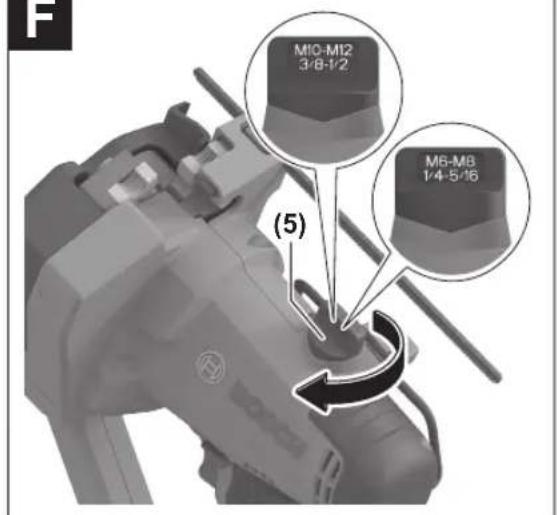
Adjust the thread size of the threaded rod to be cut on the threaded rod guide (5). This moves the M6/M8 and M10/M12 supporting surface for the threaded rod to the correct orientation.
Before pressing the release switch (14), insert the threaded rod such that its screw threads match those of the cutting jaw (3) of the stationary holder (4). If the screw threads are not aligned correctly, this could lead to a break in the cutting jaws (3) and cause personal injury from fragments being flung out. This could also damage the thread of the threaded rod such that you can no longer screw on any nuts.
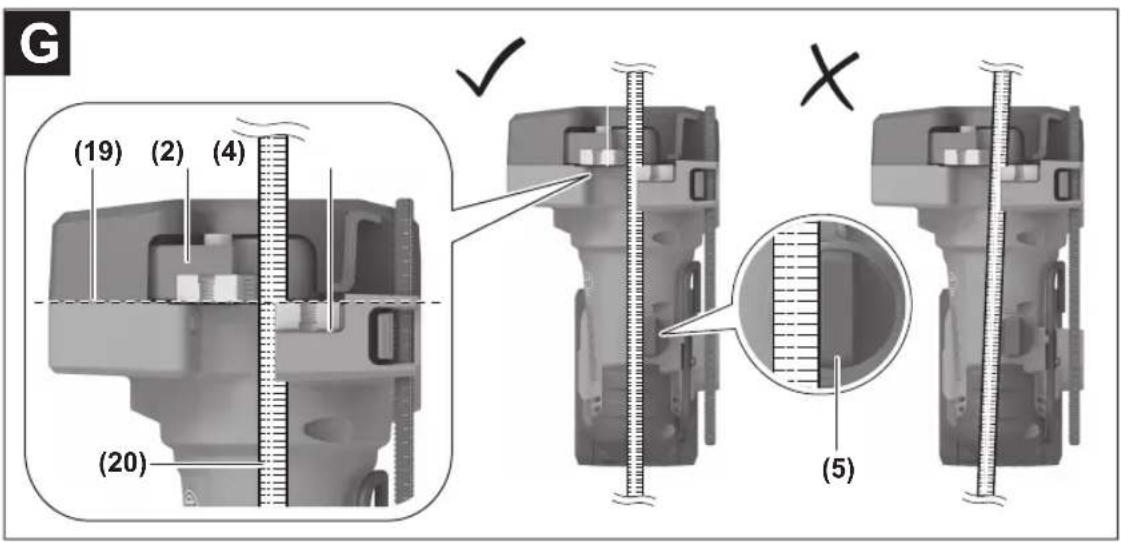
Before cutting, position the threaded rode at a right angle to the cutting line (19) (see figure G) and ensure that the threaded rod is in good contact with the previously adjusted rod guide.
To start cutting mode, ensure that the selector switch (13) is in the cutting position (position a X see figure C) and press the release switch (14) continuously. The cutting jaw on the moving holder (2) overlaps with the cutting jaw on the stationary holder (4) and then moves back. If you release the release switch (14) before completing the cut, the cutting jaws (3) will come to a stop.
Note: If you are cutting a threaded rod made from ductile metal, such as stainless steel, burrs may be generated at the end of the cut. In this case, remove the burrs with a file.
Auto-Stop Function
If you press the release switch (14) continuously, the holders (2) and (4) of the cutting jaws (3) will close once, before returning to the fully open position and then coming to a stop. Release the release switch (14) and press it again to start the next cutting sequence.
Storing the Hex Key
The hex key (8) provided can be stored on the power tool so that it is not lost. To take out the hex key, remove the rechargeable battery and pull out the hex key. After use, stow the hex key back in the power tool and insert the rechargeable battery.
Worklight
The worklight (16) illuminates the work area in poor lighting conditions.
Caution: Do not look directly into the lamp.
Press the release switch (14) gently to switch on the worklight (16) without also switching on the motor. Fully press the release switch if you wish to cut threaded rods. The worklight is automatically switched on during operation. The lamp will light up for as long as the release switch is pressed. The worklight will go out approximately 15 seconds after the release switch is released.
Threaded Rod Guide (see figures F-G)
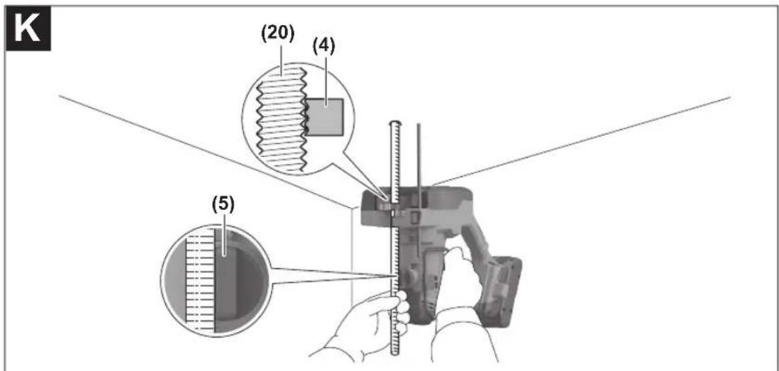
To make precise cuts, move the threaded rod guide (5) into position depending on the diameter of the threaded rod to be cut (M6/M8 or M10/M12).
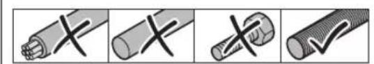
Before cutting, position the threaded rod perpendicular to the cutting line (19). Make sure that the threads of the threaded rod and the threads of the stationary cutting jaw are interlinked (see figure K). Make sure that the threaded rod is in good contact with both surfaces of the rod guide (see figure G) and hold the threaded rod in this position with a firm grip. The cutting process generates a reactive force that can tip over the threaded rod. If the threaded rod tips over, this can lead to a poor cutting quality, the threaded rod jamming, or damage to the cutting jaws or the threaded rod. You should therefore keep the threaded rod in the described orientation while cutting.
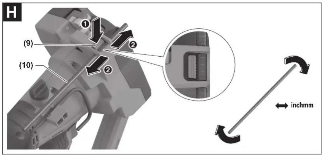
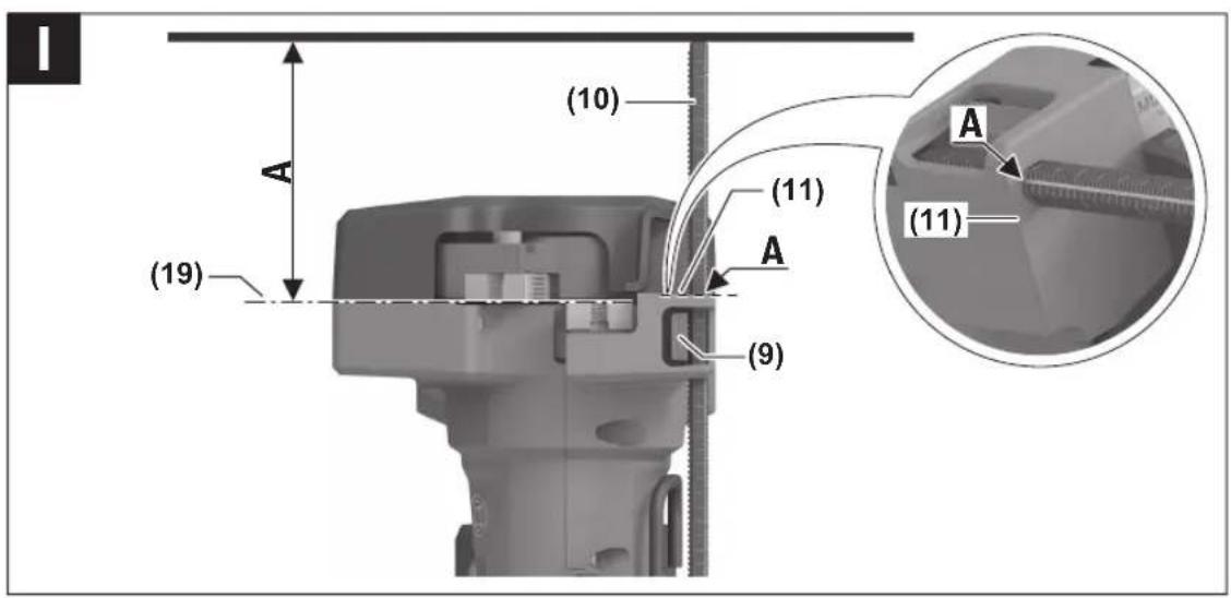
Adjusting the Depth Stop (see figures H-I)
Use the depth stop (10) if you want to cut threaded rods to the same length or if you want to cut off threaded rods with a specific overhang to a surface.
Press the (9) button and guide in the depth stop. When doing so, ensure that the toothed side of the depth stop is facing the toothed side of the button. The depth stop (10) has two measuring scales (millimetres and inches). You can turn the depth stop (10) to use the scale you require. Align the value of your required length on the depth stop (10) with the reference surface of the depth stop (11) (see figure I). To lock the depth stop, release the button (9) again.
Do not carry the power tool by the depth stop (10). Otherwise, the power tool may fall over and cause personal injury and/or damage to the power tool.
Working Advice
Prematurely Stopping the Cut
Never attempt to forcefully remove the power tool from the threaded rod. This may lead to an unexpected start, which may cause personal injury or damage to the cutting jaws (3) or the power tool.
If you want to prematurely stop a cut, let go of the release switch (14). The power tool switches off. Set the selector switch (13) to the reversal position (position b, and press and hold it while pressing the release switch (14) until the threaded rod is completely released from the cutting jaws (3) and the power tool automatically comes to a stop in the fully open position.
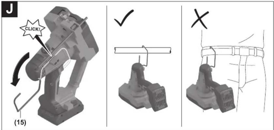
Utility Hook (see figure J)
Your power tool is equipped with a utility hook (15) for hanging it to a ladder, for example. To do this, swivel the utility hook (15) outwards.
Fold the utility hook (15) back in again until it engages when you want to use the power tool.
The utility hook (15) is not suitable for attaching the power tool to a person (e.g. to a belt). Never hang the power tool from a windy location or a potentially unstable surface.
Cutting Fixed Threaded Rods (see figure K)
Proceed as follows if you wish to cut a fixed threaded rod (e.g. a threaded rod fitted to the ceiling or wall of a building). Make sure that the threaded rod guide (5) is set according to the thread size to be cut and that the cutting jaws (3) are fully open. Position the power tool so that the threaded rod is located between the threaded jaws (3). While the threaded rod is touching the threaded rod guide (5), align the thread of the threaded rod with the thread of the stationary cutting jaw.
Hold the cut-off section of the threaded rod with your free hand because it may fall down after the cutting process.
Hold the power tool with a firm grip and expect reactive forces. Press and hold the release switch (14) until the cutting process is ended.
You can use the depth stop (10) to cut the threaded rod to length to a specified distance from a surface. Before moving the depth stop (10) in contact with the surface, ensure that the edge of the depth stop (10) and the front (1) of the power tool are free of dirt. Otherwise, you could make the surface dirty.
Adjust the depth stop (10) to the measurement you require. Position the power tool so that the edge of the depth stop is in contact with the surface from which the threaded rod is protruding and continue the cutting process as described above.
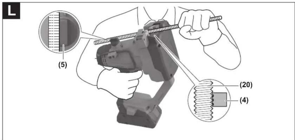
Cutting Loose Threaded Rods (see figures L-M)
For simple work, you can cut the threaded rods by holding the power tool in one hand and guiding the threaded rod to be cut with your other hand. Proceed as follows.
Make sure that the threaded rod guide (5) is set according to the thread size to be cut and that the cutting jaws (3) are fully open.
Position the power tool so that the threaded rod is located between the threaded jaws (3). While the threaded rod is touching the threaded rod guide (5), align the thread of the threaded rod with the thread of the stationary cutting jaw. Please be aware that the cut-off section will fall down after the cutting process. Hold the power tool and threaded rod with a firm grip and expect reactive forces.
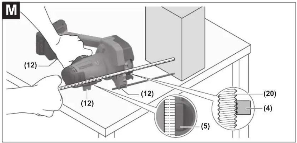
Press and hold the release switch (14) until the cutting process is ended. If you are cutting long threaded rods or large thread sizes that are hard to hold by hand, position the power tool with the side supporting surfaces (12) on a horizontal surface (see figure M).
Operate the power tool with one hand while guiding the threaded rod with your other hand with a firm grip. Proceed as follows. Make sure that the threaded rod guide (5) is set according to the thread size to be cut and that the cutting jaws (3) are fully open. Position the threaded rod so that it is located between the threaded jaws (3). While the threaded rod is touching the threaded rod guide (5), align the thread of the threaded rod with the thread of the stationary cutting jaw. Hold the power tool and threaded rod with a firm grip and expect reactive forces. Press and hold the release switch (14) until the cutting process is ended.
To cut loose threaded rods to a pre-set length, also carry out the following steps. Adjust the depth stop (10) to the measurement you require. Position a suitable object such that it is touching the depth stop (10). Position a threaded rod in relation to the power tool as described above and also ensure that it is touching the object. Ensure that you do not move the positioned object.
Storing the Power Tool
If you are storing the power tool, remove the rechargeable battery (6).
Remove dust from the cutting jaws (3) and the moving parts.
Replacing the Cutting Jaws
A pair of cutting jaws always consists of two cutting jaws (3), one of which is marked with a dot and the other of which is marked with two dots. If cutting jaws are worn or damaged, always replace them as a pair (see "Fitting the Cutting Jaws (see figures A–E)", page 22).
The pair of cutting jaws can be replaced between the moving holder (2) and the stationary holder (4).
26 | Français
Note: Ensure that the two cutting jaws (3) are oriented according to the thread size to be cut (see figure D). A cutting jaw (3) for metric thread sizes has a cutting edge for each thread size. This is located on the labelled side of the cutting jaw (3). The cutting jaws (3) can only be screwed together in the correct position; the two labelled sides should be facing each other.
Maintenance and Service
After-Sales Service and Application Service
Great Britain
Tel. Service: (0344) 7360109
GB Importer:
Robert Bosch Ltd.
Broadwater Park
North Orbital Road
Uxbridge
UB9 5HJ
You can find the link to our service addresses and warranty conditions on the last page.
In all correspondence and spare parts orders, please always include the 10-digit article number given on the nameplate of the product.
Disposal
Power tools, rechargeable batteries, accessories and packaging should be sorted for environmental-friendly recycling.

Do not dispose of power tools and batteries/rechargeable batteries into household waste!
Only for EU countries and United Kingdom:
Electrical and electronic equipment or used batteries that are no longer suitable for use must be collected separately and disposed of in an environmentally friendly manner. Use the designated collection systems. Incorrect disposal may cause harmful effects on the environment and human health, due to the potential presence of hazardous substances.
Français
Calle Robert Bosch No. 405
C.P. 50071 Zona Industrial,
Toluca - México, RFC: RBO910102QJ9
Tel.: (52) 55 528430-62
Tel.: 800 6271286
España
Risicoherkenning accudefect
EXPERT18V... | EXBA18V...
Tlf. Service Center: 44898855
(21)Discount tshibits and silicate themin should be quick
العدة الكهربائية
natural_image
Coiled black cable or strap with a loop handle and metal clip (no text or symbols visible)2 607 990 161
2 608 001 200
Legal Information and Licenses
Apache-2.0
CMSIS_5, v5.7.0
Copyright 2009-2020 Arm Limited. All rights reserved.
Licensed under the Apache License, Version 2.0
(the "License");you may not use this file except in compliance with the License. You may obtain a copy of the License at http://www.apache.org/licenses/LICENSE-2.0
Unless required by applicable law or agreed to in writing, software distributed under the License is distributed on an "AS IS" BASIS, WITHOUT WARRANTIES OR CONDITIONS OF ANY KIND, either express or implied. See the License for the specific language governing permissions and limitations under the License.
License Text
Apache License
Version 2.0, January 2004
http://www.apache.org/licenses/
TERMS AND CONDITIONS FOR USE, REPRODUCTION, AND DISTRIBUTION
- Definitions.
"License" shall mean the terms and conditions for use, reproduction, and distribution as defined by Sections 1 through 9 of this document. "Licensor" shall mean the copyright owner or entity authorized by the copyright owner that is granting the License.
"Legal Entity" shall mean the union of the acting entity and all other entities that control, are controlled by, or are under common control with that entity. For the purposes of this definition,
"control" means (i) the power, direct or indirect, to cause the direction or management of such entity, whether by contract or otherwise, or (ii) ownership of fifty percent (50%) or more of the outstanding shares, or (iii) beneficial ownership of such entity.
"You" (or "Your") shall mean an individual or Legal Entity exercising permissions granted by this License.
"Source" form shall mean the preferred form for making modifications, including but not limited to software source code, documentation source, and configuration files.
"Object" form shall mean any form resulting from mechanical transformation or translation of a Source form, including but not limited to compiled object code, generated documentation, and conversions to other media types.
"Work" shall mean the work of authorship, whether in Source or Object form, made available under the License, as indicated by a copyright notice that is included in or attached to the work (an example is provided in the Appendix below).
"Derivative Works" shall mean any work, whether in Source or Object form, that is based on (or derived from) the Work and for which the editorial revisions, annotations, elaborations, or other modifications represent, as a whole, an original work of authorship. For the purposes of this License, Derivative Works shall not include works that remain separable from, or merely link (or bind by name) to the interfaces of, the Work and Derivative Works thereof.
"Contribution" shall mean any work of authorship, including the original version of the Work and any modifications or additions to that Work or Derivative Works thereof, that is intentionally submitted to Licensor for inclusion in the Work by the copyright owner or by an individual or Legal Entity authorized to submit on behalf of the copyright owner. For the purposes of this definition, "submitted" means any form of electronic, verbal, or written communication sent to the Licensor or its representatives, including but not limited to communication on electronic mailing lists, source code control systems, and issue tracking systems that are managed by, or on behalf of, the Licensor for the purpose of discussing and improving the Work, but excluding communication that is conspicuously marked or otherwise designated in writing by the copyright owner as "Not a Contribution."
"Contributor" shall mean Licensor and any individual or Legal Entity on behalf of whom a Contribution has been received by Licensor and subsequently incorporated within the Work.
-
Grant of Copyright License. Subject to the terms and conditions of this License, each Contributor hereby grants to You a perpetual, worldwide, non-exclusive, no-charge, royalty-free, irrevocable copyright license to reproduce, prepare Derivative Works of, publicly display, publicly perform, sublicense, and distribute the Work and such Derivative Works in Source or Object form.
-
Grant of Patent License. Subject to the terms and conditions of this License, each Contributor hereby grants to You a perpetual, worldwide, non-exclusive, no-charge, royalty-free, irrevocable (except as stated in this section) patent license to make, have made, use, offer to sell, sell, import, and otherwise transfer the Work, where such license applies only to those patent claims licensable by such Contributor that are necessarily infringed by their Contribution(s) alone or by combination of their Contribution(s) with the Work to which such Contribution(s) was submitted. If You institute patent litigation against any entity (including a cross-claim or counterclaim in a lawsuit) alleging that the Work or a Contribution incorporated within the Work constitutes direct or contributory patent infringement, then any patent licenses granted to You under this License for that Work shall terminate as of the date such litigation is filed.
-
Redistribution. You may reproduce and distribute copies of the Work or Derivative Works thereof in any medium, with or without modifications, and in Source or Object form, provided that You meet the following conditions:
(a) You must give any other recipients of the Work or Derivative Works a copy of this License; and
(b) You must cause any modified files to carry prominent notices stating that You changed the files; and
(c) You must retain, in the Source form of any Derivative Works that You distribute, all copyright, patent, trademark, and attribution notices from the Source form of the Work, excluding those notices that do not pertain to any part of the Derivative Works; and
(d) If the Work includes a "NOTICE" text file as part of its distribution, then any Derivative Works that You distribute must include a readable copy of the attribution notices contained within such NOTICE file, excluding those notices that do not pertain to any part of the Derivative Works, in at least one of the following places: within a NOTICE text file distributed as part of the Derivative Works; within the Source form or documentation, if provided along with the Derivative Works; or, within a display generated by the Derivative Works, if and wherever such third-party notices normally appear. The contents of the NOTICE file are for informational purposes only and do not modify the License.
You may add Your own attribution notices within Derivative Works that You distribute, alongside or as an addendum to the NOTICE text from the Work, provided that such additional attribution notices cannot be construed as modifying the License. You may add Your own copyright statement to Your modifications and may provide additional or different license terms and conditions for use, reproduction, or distribution of Your modifications, or for any such Derivative Works as a whole, provided Your use, reproduction, and distribution of the Work otherwise complies with the conditions stated in this License.
-
Submission of Contributions. Unless You explicitly state otherwise, any Contribution intentionally submitted for inclusion in the Work by You to the Licensor shall be under the terms and conditions of this License, without any additional terms or conditions. Notwithstanding the above, nothing herein shall supersede or modify the terms of any separate license agreement you may have executed with Licensor regarding such Contributions.
-
Trademarks. This License does not grant permission to use the trade names, trademarks, service marks, or product names of the Licensor, except as required for reasonable and customary use in describing the origin of the Work and reproducing the content of the NOTICE file.
-
Disclaimer of Warranty. Unless required by applicable law or agreed to in writing, Licensor provides the Work (and each Contributor provides its Contributions) on an "AS IS" BASIS, WITHOUT
WARRANTIES OR CONDITIONS OF ANY KIND, either express or implied, including, without limitation, any warranties or conditions of TITLE, NON-INFRINGEMENT, MERCHANTABILITY, or FITNESS FOR A PARTICULAR PURPOSE. You are solely responsible for determining the appropriateness of using or redistributing the Work and assume any risks associated with Your exercise of permissions under this License.
-
Limitation of Liability. In no event and under no legal theory, whether in tort (including negligence), contract, or otherwise, unless required by applicable law (such as deliberate and grossly negligent acts) or agreed to in writing, shall any Contributor be liable to You for damages, including any direct, indirect, special, incidental, or consequential damages of any character arising as a result of this License or out of the use or inability to use the Work (including but not limited to damages for loss of goodwill, work stoppage, computer failure or malfunction, or any and all other commercial damages or losses), even if such Contributor has been advised of the possibility of such damages.
-
Accepting Warranty or Additional Liability. While redistributing the Work or Derivative Works thereof, You may choose to offer, and charge a fee for, acceptance of support, warranty, indemnity, or other liability obligations and/or rights consistent with this License. However, in accepting such obligations, You may act only on Your own behalf and on Your sole responsibility, not on behalf of any other Contributor, and only if You agree to indemnify, defend, and hold each Contributor harmless for any liability incurred by, or claims asserted against, such Contributor by reason of your accepting any such warranty or additional liability.
END OF TERMS AND CONDITIONS
BSD-3-Clause
Infineon TLE987x_DFP, v1.5.0
Copyright (c) 2015-2017, Infineon Technologies AG. All rights reserved.
Redistribution and use in source and binary forms, with or without modification, are permitted provided that the following conditions are met:
-
Redistributions of source code must retain the above copyright notice, this list of conditions and the following disclaimer.
-
Redistributions in binary form must reproduce the above copyright notice, this list of conditions and the following disclaimer in the documentation and/or other materials provided with the distribution.
-
Neither the name of the copyright holder nor the names of its contributors may be used to endorse or promote products derived from this software without specific prior written permission.
THIS SOFTWARE IS PROVIDED BY THE COPYRIGHT HOLDERS AND CONTRIBUTORS “AS IS†AND ANY EXPRESS OR IMPLIED WARRANTIES, INCLUDING, BUT NOT LIMITED TO, THE IMPLIED WARRANTIES OF MERCHANTABILITY AND FITNESS FOR A
PARTICULAR PURPOSE ARE DISCLAIMED. IN NO EVENT SHALL THE COPYRIGHT HOLDER OR CONTRIBUTORS BE LIABLE FOR ANY DIRECT, INDIRECT, INCIDENTAL, SPECIAL, EXEMPLARY, OR CONSEQUENTIAL DAMAGES (INCLUDING, BUT NOT LIMITED TO, PROCUREMENT OF SUBSTITUTE GOODS OR SERVICES; LOSS OF USE, DATA, OR PROFITS; OR BUSINESS INTERRUPTION) HOWEVER CAUSED AND ON ANY THEORY OF LIABILITY, WHETHER IN CONTRACT, STRICT LIABILITY, OR TORT (INCLUDING NEGLIGENCE OR OTHERWISE) ARISING IN ANY WAY OUT OF THE USE OF THIS SOFTWARE, EVEN IF ADVISED OF THE POSSIBILITY OF SUCH DAMAGE.
WARRANTY DISCLAIMER
This product contains Open Source Software components which underlie Open Source Software Licenses. Please note that Open Source Licenses contain disclaimer clauses. The text of the Open Source Licenses that apply are included in this manual under "Legal Information and Licenses".
Legal Information and Licenses
Servicekontakte
Service Contacts
Contacts de Service
https://www.bosch-pt.com/serviceaddresses
Garantiebedingungen Guarantee Conditions Conditions de Garantie Condiciones de Garantía

https://www.bosch-pt.com/guarantee/202507