
DBE 250 R - Electric drill Eibenstock - Free user manual and instructions
Find the device manual for free DBE 250 R Eibenstock in PDF.

| Product type | Diamond core drill (electric drill for concrete, stone, masonry) |
| Brand | Eibenstock |
| Model | DBE 250 R (EBM 250/2 RP in the manual) |
| Rated voltage | 230 V ~ |
| Frequency | 50 / 60 Hz |
| Power consumption | 2500 W |
| Rated current | 11,5 A |
| Max drilling diameter | 250 mm (slow speed), 152 mm (fast speed) |
| Tool holder | 1 1/4" UNC (male thread) |
| Speeds (no load) | I: 360 rpm, II: 850 rpm |
| Protection class | I (with protective conductor) |
| IP rating | IP 20 |
| Weight (motor only) | 10,5 kg |
| Weight of drill stand (BST 250) | 15,5 kg |
| Dimensions of stand (BST 250) | 430 x 330 x 1040 mm |
| Column length (stand) | 995 mm |
| Water supply | GARDENA connection, max. pressure 3 bar |
| Safety device | PRCD (residual current device), mechanical protection (friction coupling) and electronic protection (overload indicator) |
| Stand tilt | 0° to 45° (adjustable) |
| Included accessories | Wrenches SW 32 and SW 41, instruction manual, integrated PRCD |
| Maintenance | Change gear oil after 150 hours, check carbon brushes after 200 hours, clean after use |
| Repairability | Repairs by an Eibenstock authorized specialist; spare parts available |
| Warranty | 12 months (material and manufacturing defects) |
| Standards | EN 62841-1, directives 2011/65/EU, 2014/30/EU, 2006/42/EC |
Frequently Asked Questions - DBE 250 R Eibenstock
User questions about DBE 250 R Eibenstock
0 question about this device. Answer the ones you know or ask your own.
Ask a new question about this device
Download the instructions for your Electric drill in PDF format for free! Find your manual DBE 250 R - Eibenstock and take your electronic device back in hand. On this page are published all the documents necessary for the use of your device. DBE 250 R by Eibenstock.
USER MANUAL DBE 250 R Eibenstock
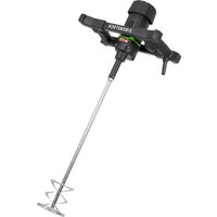
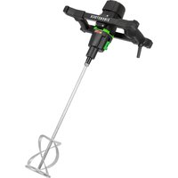
natural_image
Exterior view of a black and green industrial oil pump with attached hoses (no visible text or symbols)EBM 250/2 RP
Wichtige Hinweise
natural_image
Warning symbol of a lightning bolt inside a triangle (no text or numbers)natural_image
Simple line drawing of a trash bin with crossed lines indicating no waste or discharge (no text or symbols)Nur für EU-Länder
Lothar Lässig
General Manager
Eibenstock, 12.12.2024
Frank Markert
Head of Engineering
Important Instructions
Important instructions and warnings are labelled with symbols on the machine:

Before you start working, read the operating instructions of the machine.

Work concentrated and carefully. Keep your work-place clean and avoid dangerous situations.

In order to protect the user, take precautions.
To protect yourself, it is recommended that you take the following protective measures:

Wear safety goggles

Wear safety helmet

Use ear protection

Wear protective gloves

Wear protective boots
Warning signs

Warning of general danger
Warning of dangerous voltage
Warning of hot surface

Danger of being ripped or cut
Technical Data
Diamond core drill EBM 250/2 RP
| Rated voltage: | 230 V ~ |
| Power input: | 2500 W |
| Rated current: | 11.5 A |
| Frequency: | 50 / 60 Hz |
| Max. drilling diameter: | 250 mm |
| Spindle connection: | 1 1⁄4" UNC |
| Protection class: | I |
| Degree of protection: | IP 20 |
| Net weight: | about 10.5 kg |
| Interference suppression: | EN 55014 and EN 61000 |
| Order number | 0352H000 |
| Speed | Rated speed | Max. drilling diameter |
| I | 360 rpm | 250 mm |
| II 850 | rpm 152 mm |
Available accessories:
| Item | Order no. |
| Diamond drill rig BST 152 with quick -change adapter | 09631000 |
| Fastening set concrete / stone | 35720000 |
| Copper rings for easy removal of the drill bit | 35450000 |
| Adapter 1 1/4" i - 1/2" i | 35116000 |
| Quick action bracing unit | 35730000 |
| Water tank 10 l metal | 35810000 |
| Wet/dry vacuum cleaner DSS 25 A | 09915000 |
| Wet/dry vacuum cleaner DSS 25 M | 09917000 |
| Diamond drill bits ∅ 25 - 162 mm | |
| Drill bit extensions |
Supply
Diamond core drill with ball valve and GARDENA connector, PRCD protective switch, operating instructions, one spanner SW 32 and one spanner SW 41 in a cardboard box
Intended use
The EBM 250/2 RP diamond core drilling machine is intended for commercial use. It may only be operated by trained personnel. The machine is intended exclusively for wet drilling of concrete, stone and masonry in conjunction with suitable wet core bits. The machine may only be operated in a diamond drill rig suitable for this purpose.

Safe work with the machine is only possible if you read this operating instruction and follow the instructions contained strictly.
Additionally, the general safety instructions of the leaflet supplied with the tool must be observed. Prior to the first use, the user should absolve a practical training. Save all warnings and instructions for future reference.

If the mains cable gets damaged or cut during use, do not touch it, but instantly pull the plug out of the socket. Never use the tool with a damaged mains cable.
When drilling in ceilings or walls make sure you will not cut through electrical mains, gas or water pipes. Use metal detection systems if needed.
Prior to the start of your work, consult a statics specialist to determine the exact drilling position.
If drilling through ceilings, secure the place below, because the core may fall downward.
Pay attention that the tool is not exposed to direct rain.
- Do not use the tool in an environment with danger of explosion.
- Do not use the tool standing on a ladder.
- Do not drill in asbestos-containing materials.
- Never carry the tool at its cable and always check the tool, cable and plug before use. Have damages only repaired by specialists. Insert the plug into the socket only when the tool switch is off.
■ Modifications of the tool are prohibited. - The machine should only work under supervision of sbd. Plug and switch the machine off if it is not under supervision, e.g. in case of putting up and stripping down the machine, in case of voltage drop or when fixing or mounting an accessory.
- Switch the machine off if it stops for whatever reason. You avoid that it starts suddenly and not under supervision.
- Do not use the machine if a part of the housing is damaged or in case of damages on the switch, the cable or plug.
- During work, always lead the mains cable, extension cable and extraction hose to the back away from the machine.
- Power tools have to be inspected visually by a specialist in regular intervals.
- When using the drill, cooling water is never allowed to get into the motor and all electrical parts.
-
Overhead-drillings only with suitable safety measures (water collection).
-
After an interruption of your work, only switch the machine on again after having checked that the drill bit can be turned freely.
■ The tool may be used with the drill rig only. - Do not touch rotating parts.
- Persons under 16 years of age are not allowed to use the tool.
- During use, the user and other persons standing nearby have to wear suitable ear protectors, goggles, helmets, protective gloves and boots.


- Always work concentrated and carefully. Do not use the tool when you are lacking in concentration.
For further safety instructions, please refer to the enclosure!
Fixing to Drill Rig
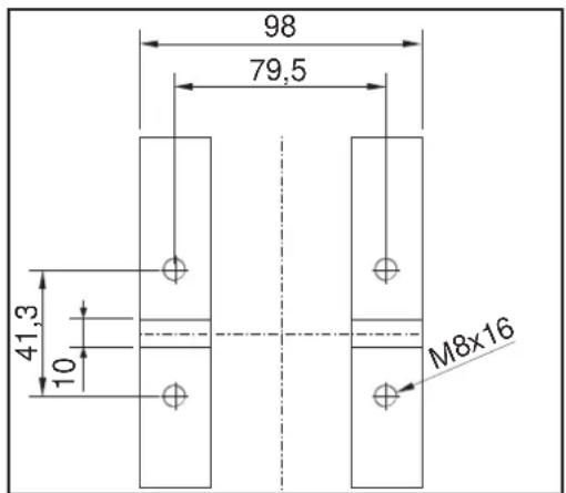
The EBM 250/2 RP is attached to the drill stand at the base of the gearbox using 4 M8 hexagon socket head screws. Only insert the machine into a stable drill stand that is equipped with precise guides and ensure that the machine axis is aligned parallel to the drill stand column. Only use drill stands that are sufficiently stable. The use of a water collection ring is recommended.
Electrical Connection
natural_image
Warning symbol of a lightning bolt inside a triangle (no text or numbers)The EBM 250/2 RP is designed in protection class I. To protect the operator, the machine may only be operated if a residual current device is available. For this reason, the device is supplied with a residual current circuit breaker (PRCD) integrated in the cable as standard.

Attention!
- The PRCD-safety switch must not lay in water.
- PRCD-safety switch must not be used to switch the tool on and off.
- Before you start working, check the proper functioning by pressing the TEST button.
Before commissioning, check that the mains voltage and mains frequency match the specifications on the rating plate. Voltage deviations of +6 % and -10 % are permissible. Only use a 3-core extension cable with a protective earth conductor and a sufficient cross-section (min. 2.5 mm ^4 ) A cross-section that is too small can lead to excessive power loss and overheating of the machine and cable.
Water Connection
If the core bit is not sufficiently cooled with water, the diamond segments can heat up, which can lead to damage and weakening of the diamond segments. For this reason, care should always be taken to ensure that the cooling system of the core bit is not blocked.
To supply the drill with water, proceed as follows:
- Connect the machine to the water supply or to a pressurised water tank using the GARDENA plug nipple.
- Only operate the machine with clean water and ensure a sufficient water supply, as the seals will be damaged if the machine is operated dry.
- Caution! The maximum water pressure must not exceed 3 bar!
- Ensure that the segments are sufficiently cooled. Sufficient cooling is ensured if the drilling water is clear.
- If the hole that has just been drilled is to be enlarged, it must be sealed to ensure a sufficient flow of cooling water.
■ Always use a water collection ring when working overhead.
■ Empty the water system if there is a risk of frost.
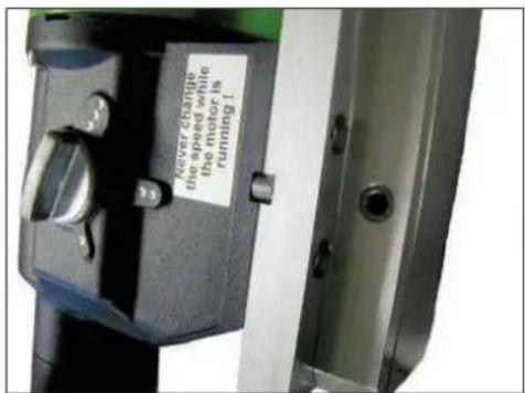
Changing Gears
The EBM 250/2 RP is equipped with a mechanical 2-speed gearbox in an oil bath.
The speed of the machine is adapted to the drilling diameter (see device characteristics for details). To do this, the gear switch is turned to the faster or slower gear. The speed may only be changed when the machine is at a standstill; it may be necessary to support the shifting process by turning the working spindle slightly.

Warning!
- Never use force and only switch over when the machine is running down or at a standstill!
- Do not use tools such as pliers or hammers to switch over!
Drill bits
Diamond drill bits with a 1/4' UNC internal thread can be screwed directly onto the working spindle. Adapters for drill bits with an R 12 ' external thread are available as accessories. Only use drill bits that are suitable for the material to be drilled. The core drilling machine will last longer if only round and non-deformed drill bits are used. Make sure that the diamond segments are sufficiently free-cutting in relation to the drill bit body.
Drill Bit Changing


Attention!
The tool is heavy and can become very hot during use or when grinding. There is a risk of burns, cuts, cracks or bruises on the segments. Therefore, always use protective gloves when changing the tool.
The drill spindle is equipped with a right-hand thread. A 32 mm open-ended spanner must always be used as a counterholder, which is placed on the drill spindle. Never use hammer blows to loosen the drill bit, as this can cause damage to the core drilling machine. Loosening the drill bit is facilitated by applying a little waterproof grease to the thread of the drill spindle and a copper ring between the spindle and drill bit.
Using the Drilling Unit
To start up the machine safely, follow these instructions
Information on the place of use
- Remove all obstacles that could hinder the work process from the place of use.
- Ensure that the place of use is sufficiently lit.
- Observe the specified conditions for connection to the power supply.
- Lay the electrical cables in such a way that it is not possible for the tool to damage them.
■ Make sure that you always have an adequate view of the work area. All necessary control elements and safety devices must be accessible at all times. - To avoid accidents, keep other people away from your work area.
Space required for operation and maintenance
If possible, maintain a free space of approx. 2 m around the machine for operation and maintenance so that you can work safely and intervene immediately in the event of malfunctions.
Preparation
- When drilling in blocks, make sure that these blocks are well anchored and secured.
- Make sure that the statics are not violated before drilling into load-bearing parts. Follow the instructions of the professionals responsible for the planning.
■ Make sure that no gas, water or electricity lines are damaged during drilling. - Be careful not to touch any metal parts of the machine when drilling through walls or floors. In these areas, power cables may be located under water.
- Care should be taken to ensure that the drill core does not fall and cause injury to persons or damage to property. Clear and secure the work area.
- Install a suitable device to contain the drill core if it could cause damage when it falls out.
■ Make sure that the drill bit is properly secured. - Use the correct tool for the material to be worked.
Fastening of the Drill Rig
The diamond core drilling machine EBM 250/2 RP may be operated only when it is mounted in a drill stand. We wish to point out a few important mounting variants, since the drill stand is not included in the scope of delivery. The operating instructions for the drill stand must be observed. When using a vacuum fastening, make sure that the vacuum is sufficiently strong (at least -0.8 bar). The seals must not be worn.
Caution! Not for wall and ceiling drilling!
Do not forget that you can only unscrew the levelling screw to a certain point in order not to destroy the vacuum.
The most commonly used type of mounting is the plug mounting.
If possible, use metal plugs. The plug diameter must not be smaller than 12 mm.
- To properly mount the drilling unit, you need the mounting set (order no. 35720000).
- Drill a hole with a diameter of 16 mm, 50 mm deep and remove dust.
- Insert an anchor and expand it using the setting tool.
- Screw the threaded rod into the anchor.
- Place the drilling unit with the slot in the foot on the threaded rod.
- Put the disc on and screw the wing nut on tightly.
- Adjust the drilling unit using the four screws in the base plate.
Drilling
Vertical drilling
■ Switch the PRCD to On.
- Open the water supply.
- Switch on the motor without the drill bit touching the surface.
- Turn the handle to lower the drill bit until it touches the surface.
- To ensure that the drill bit is centred precisely, keep the feed low for the first centimetre of cutting depth.
- You can then drill faster. If the drilling speed is too low, this will reduce performance. If the drilling speed is too high, the diamond segments will quickly become blunt.
Angular drilling
- Remove the screw in the foot plate that locks the column at 90°.
- Loosen the two screws at the foot of the column and swivel the column to the desired angle.
■ Retighten the two screws. - Drill very slowly at the beginning, as the bit only grips the material with a fraction of its cutting surface. If you drill too fast or with too much pressure, the bit can go off course.
If you notice while drilling that the feed rate is becoming very slow, you have to apply more force and the water from the drill hole is clear and mixed with metal splinters, you have encountered reinforcing bars. To cut through the reinforcement without any problems, reduce the pressure on the drill bit. After you have cut through the reinforcement, you can increase the pressure on the drill bit again.
Drill bit extension
If you need to drill deeper than the effective length of your drill bit:
- First, only drill as far as the effective length of the bit allows.
- Remove the bit and release the drill core from the hole without moving the core drilling rig.
- Push the bit back into the drill hole.
Screw a suitable extension between the drill bit and the motor. If the drill bit adapter is 114 , do not forget the copper rings to make it easier to loosen the drill bit.
Overload Protection
The EBM 250/2 RP is equipped with mechanical and electronic overload protection to protect the operator, motor and drill bit.
Mechanical: If the drill bit is suddenly blocked in the hole, a clutch will slip disengaging the drill spindle from the motor.
Electronic: To warn the user against overstressing the tool by applying to high feed force, a LED is mounted on the motor cap. It does not light during no-load run or at normal load. In case of over- load, the LED lights red. Now the tool must be discharged. In case of longer non-observation of the red indication, the electronics will independently cut the unit off. After discharge and switching the tool off and on again, you can continue working.
Thermal: In case of permanent overload, a thermocouple protects the motor against destruction. Here also, the user is warned by the overload indicator. Shortly before the maximum temperature is reached, the indicator flashes red. In that case, the tool switches off and can only be restarted after a certain cooling-down period (approx. 2 minutes). The overload indicator flashes until the machine has cooled sufficiently and can be used again. The cooling-down time depends on the temperature of the motor winding and ambient temperature.
Safety clutch
The slip clutch is designed to absorb shocks and overloads. To maintain its functionality, it may slip for a maximum of 2 seconds. If it shows excessive wear, it must be replaced by an authorised specialist workshop.
Segmental fracture
If a diamond segment, parts of the reinforcement or similar comes loose during drilling and the drill bit is blocked as a result, the drilling operation must be stopped.
Drill a new hole with the same centre. The diameter should be 15 to 20 mm larger.
Do not attempt to finish the drilling with a different drill bit of the same diameter!
After drilling
When you have finished drilling:
- Pull the drill bit out of the hole.
- Switch off the motor. Use the motor switch and not the PRCD for this purpose.
- Close the water supply.
Remove the drill core if it remains in the drill bit - Separate the drill bit from the motor.
- Place the drill bit vertically.
- Tap the pipe lightly with a wooden hammer handle until the drill core slides out. Never force the drill bit against a wall or use tools such as hammers or open-ended spanners, as this can cause the pipe to warp, preventing the drill core from being removed and the drill bit from being reused.
Removing the drill core from a blind hole
- Break off the core with a wedge or lever.
- Lift out the core with a suitable pair of pliers or drill a hole in the core, screw an eye bolt into it and pull it out using the bolt.
Care and Maintenance
Before the beginning of the maintenance or repair works you have to disconnect the plug from the mains!
Repairs must only be carried out by suitably qualified and experienced engineers. After any repair the machine must be tested by a qualified electrician.
The power tool has been designed to require a minimum of maintenance. However, the following points must always be observed:
■ After finishing the drilling work, the core drilling unit must be cleaned. Then grease the thread of the drill spindle. The ventilation slots must always be kept clean and open. Ensure that no water enters the interior of the core drilling machine during cleaning.
■ After the first 150 operating hours, the gear oil must be changed. By changing the gear oil, the service life of the gear can be increased many times over.
■ After approx. 200 operating hours, the carbon brushes must be checked by an electrician and replaced if necessary (only original carbon brushes may be used).
- Quarterly inspection of switches, cables and plugs by an electrician.
Our customer service will be pleased to help you with questions regarding repair, maintenance and spare parts supply.
The EIBENSTOCK application consulting team will be pleased to help you if you have questions about our products and their accessories.
Environmental Protection

Raw material recycling instead of waste disposal
In order to avoid damages on transportation, the power tool has to be delivered in sturdy packing. The packing as well as the tool and its accessories are made of recyclable materials and can be disposed accordingly. The tool's plastic components are marked according to their material, which makes it possible to remove environmental friendly and differentiated because of available collection facilities.
Only for EU countries

natural_image
Simple line drawing of a trash bin with no text or symbolsDo not dispose of electric tools together with household waste material!
In observance of European Directive 2012/19/EU on waste electrical and electronic equipment and its implementation in accordance with national law, electric tools that have reached the end of their life must be collected separately and returned to an environmentally compatible recycling facility.
Noise Emission / Vibration
The noise of this power tool is measured according to EN 62841-3-6. The sound pressure level at the workplace can exceed 85 dB (A); in this case, sound insulation measures are required for the operator.

Wear hearing protection!
Cut-off brushes
The power tool is equipped with self-disconnecting carbon brushes to protect the motor. If the brushes are worn, the machine will switch off automatically. In this case, both carbon brushes must be replaced at the same time by an authorised electrician using original carbon brushes.
In Case of Malfunction
In the event of a fault, switch off the machine and disconnect it from the power supply. Work on the machine's electrical system must only be carried out by a qualified electrician.
Trouble Shooting
| Error | Possible cause | Remedy |
| Device does not work | Power supply interrupted | Plug in another electrical device to check that it is working. |
| Defective power cable or plug | Have checked and replaced if necessary by a qualified electrician | |
| Switch defective | Have it checked and replaced if necessary by a qualified electrician. | |
| PRCD switch off | Switch on PRCD switch (RESET) | |
| Motor running – drill bit not turning | Defective gearbox | Have the unit repaired at an authorised repair centre. |
| Drilling speed decreases | Water pressure/water flow too high | regulate the amount of water |
| Drill bit defective | Check drill bit for damage and replace if necessary | |
| Defective gearbox | Have the unit repaired at an authorised repair centre. | |
| polished drill bit | Sharpen drill bit on sharpening stone while running water | |
| Engine stalls | Device comes to a stop. Hold the device straight | |
| Device too warm – motor overload protection has tripped | Relieve the device and allow it to start up again by pressing the switch | |
| Carbon brushes worn – shut-off carbon switches off | Have both carbon brushes changed by a qualified electrician | |
| Water leaking from the gearbox. | Defective shaft seals | Have the unit repaired at an authorised workshop. |
Warranty
According to our general terms and conditions, a warranty period of 12 months applies to material defects in business transactions with companies (proof by invoice or delivery note).
Excluded are damages that can be attributed to natural wear and tear, overuse or improper handling. Damages that can be attributed to material or manufacturing defects will be remedied free of charge by repair or replacement. Complaints can only be accepted if the device is sent to the supplier or an authorised workshop in Eibenstock in an undismantled state.
EU - Declaration of Conformity
We declare under our sole responsibility that the product described under "Technical Data" is in conformity with the following standards or standardization documents:
EN 62841-1:2016-07
according to the provisions of the directives 2011/65/EU, 2014/30/EU, 2006/42/EG
Technical file (2006/42/EC) at:
Lothar Lässig
General Manager
Frank Markert
Head of Engineering
GB - Declaration of Conformity
We declare under our sole responsibility that the product described under "Technical Data" is in conformity with the following standards or standardization documents:
BS EN 62841-1:2016-07
according to the provisions of the directives 2011/65/EU, 2014/30/EU, 2006/42/EG
Technical file (2006/42/EC) at:
Lothar Lässig
General Manager
Eibenstock,12.12.2024
Subject to change without notice.
Frank Markert
Head of Engineering
FRANÇAIS
natural_image
Warning symbol of a lightning bolt inside a triangle (no text or numbers)natural_image
Simple line drawing of a trash bin with no text or symbolsLothar Lässig
General Manager
Frank Markert
Head of Engineering
Eibenstock, 12.12.2024
natural_image
Warning symbol of a lightning bolt inside a triangle (no text or numbers)natural_image
Simple line drawing of a trash bin with crossed lines indicating no waste or discharge (no text or symbols)Frank Markert
Head of Engineering
Eibenstock, 12.12.2024
natural_image
Warning symbol of a lightning bolt inside a triangle (no text or numbers)natural_image
Simple line drawing of a trash bin with no text or symbolsKun for EU-lande
Lothar Lässig
General Manager
Frank Markert
Teknisk chef
Eibenstock, 12.12.2024
natural_image
Warning symbol of a lightning bolt inside a triangle (no text or numbers)natural_image
Symbol of a trash bin crossed with diagonal lines, representing waste sorting or disposal (no text or labels)Lothar Lässig
Direttore generale
Frank Markert
natural_image
Warning symbol of a lightning bolt inside a triangle (no text or numbers)natural_image
Simple line drawing of a trash bin with crossed lines indicating no waste or discharge (no text or symbols)PORTUGUÊS
Notas importantes
natural_image
Warning symbol of a lightning bolt inside a triangle (no text or numbers)natural_image
Simple line drawing of a trash bin with crossed lines indicating no waste or discharge (no text or symbols)Důležité poznámky
natural_image
Warning symbol of a lightning bolt inside a triangle (no text or numbers)natural_image
Symbol of a trash bin with crossed lines indicating no waste or discharge (no text or labels)Frank Markert
natural_image
Warning symbol of a lightning bolt inside a triangle (no text or numbers)natural_image
Simple line drawing of a trash bin with no text or symbolsTylko dla krajów EU
Lothar Lässig
General Manager
Frank Markert
Head of Engineering
Eibenstock, 12.12.2024
natural_image
Warning symbol of a lightning bolt inside a triangle (no text or numbers)Frank Markert
Head of Engineering
Eibenstock, 12.12.2024
natural_image
Six circular icons representing different person and footwear styles (no text or symbols)


الاشارات التحذيرية
التحذير من خطر عام
natural_image
Warning symbol of a lightning bolt inside a triangle (no text or numbers)! انتباه
natural_image
Simple line drawing of a trash bin with crossed lines indicating no waste or plastic (no text or symbols)FRANK MARKERT
Head of Engineering
12.12.2024
. عرضة لل tangير
ΕΛΛΗΝΙΚΑ
natural_image
Warning symbol of a lightning bolt inside a triangle (no text or numbers)natural_image
Symbol of a trash bin with no text or labelsLothar Lässig
Γενικός Διευθυντής
Frank Markert
natural_image
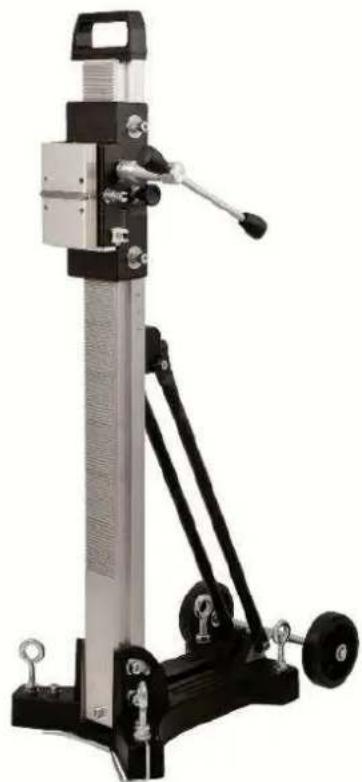
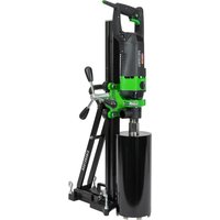
Mechanical testing apparatus with green and black components mounted on a stand (no visible text or symbols)BST 250
natural_image
Mechanical device with articulated arms and wheels, no visible text or symbolsBST 300
DEUTSCH
Wichtige Hinweise
natural_image
Six circular icons representing different human and footwear behaviors (head, glasses, hat, hand, boot, boots), no text or symbols present.natural_image
Close-up of a mechanical device with black and metallic components and a black lever handle (no visible text or symbols)natural_image
Close-up of a mechanical clamp or bracket component with metallic fittings and mounting holes (no visible text or symbols)natural_image
Close-up of a mechanical lever with a black handle and arrow pointing to a measurement scale (no text or symbols visible)natural_image
Mechanical device with attached lever and adjustment knobs, no visible text or symbolsImportant instructions and warnings are indicated by symbols on the machine:
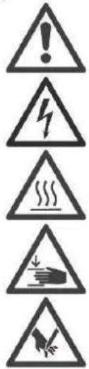
Warning of general danger
Warning of dangerous electrical voltage
Warning of hot surface
The machine, drill bit and drill stand are heavy – caution: risk of crushing
Risk of tearing or cutting
To protect yourself, it is recommended that you take the following precautions:

Use hearing protection
Use eye protection
Use a safety helmet
Use protective gloves
Use protective footwear
Technical specifications
Diamond drill stand BST 250, BST 300
| BST 250 | BST 300 | |
| Dimensions | 430 x 330 x 1040 mm | 540 x 330 x 1100 mm |
| Column length: | 995 mm | 995 mm |
| Weight | 15,5 kg | 18,5 kg |
| Max. drilling diameter | 250 mm | 350 mm |
| Inclination | 0° bis 45° | |
| Lock in end position: | Yes | |
| Motor mounting: | quick-release plate | |
| Adjustment to base: | 4 adjustment screws / 2 spirit levels | |
| Order number | 09631000 | 09662600 |
Available special accessories:
| Item | Order no. |
| Fastening set (concrete) | 35720000 |
| Fastening set (brickwork) | 35724000 |
| Spare dowel | 35722000 |
| Brickwork – dowel | 35725000 |
| Quick action bracing unit | 35730000 |
Scope of delivery
Diamond drill stand with turnstile, hexagon socket wrenches SW 6 and SW 8, 4 hexagon socket screws M 8 x 25 and operating instructions in a box.
Application for Intended Purpose
The diamond drill stand is designed for diamond core drilling machines that are attached using a mounting plate. Please note that the maximum diameter of the drill bit must not exceed the value specified in the table (see technical data)!
When drilling overhead, a water collection device must always be used to collect and dispose of the drilling water.
The manufacturer accepts no liability if the product is not used for its intended purpose or is used for other purposes.
Use

After each new adjustment, check that the screws are tight so that the drill stand can be used safely.
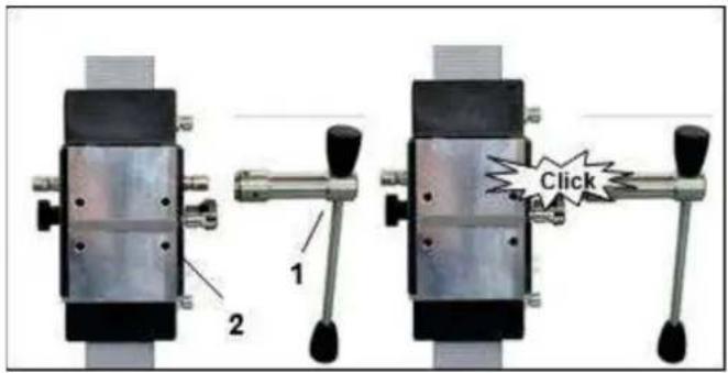
Attaching the turnstile
■ Attach the turnstile (1) to the left or right of the carriage (2). This depends on the work to be carried out.
- Please check that the turn-stile (1) is correctly positioned.
Fastening of the Drill Rig
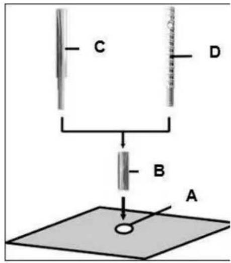
Fastening by means of dowels in concrete
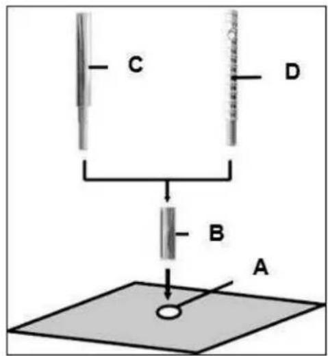
■ Mark the position of the mounting hole on the surface to be drilled.
- Drill the hole (∅ 16) 50 mm deep (A) into which the M12 dowel (B) is to be inserted; insert the dowel and expand it with the dowel setting tool (C).
- Screw the quick-release screw (D) into the dowel.

Masonry anchors must be used for masonry.
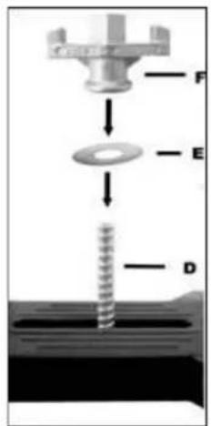
- Put the stand in place.
- Secure the washer (E) and finally the fastening nut (F) on the quick-release screw (D).
- Tighten the nut (F) with a 27 mm wrench.
■ Before and after tightening the nut (F), adjust the 4 adjusting screws as necessary to adapt to the ground.

Be sure to check that the stand is securely mounted.
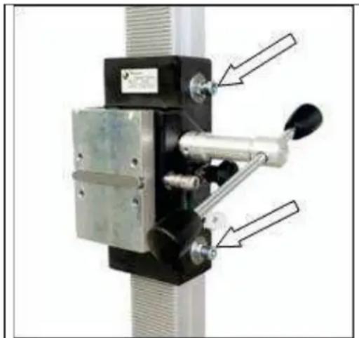
Fastening by means of quick action bracing unit
In order to be able to brace the drill stand using the quick-release column, the distance to the opposite wall must be between 1.7 m and 3 m.
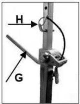
Position the drill stand. Place the quick-release column as close as possible behind the column on the stand base. Secure the drill stand by turning the crank (G clockwise. Secure the setting with the corresponding bolt (H).
Caution!
It is important that the drill stand is firmly secured to the ground. Incorrectly secured drill stands can cause injury to the operator and damage to the drill unit.
Movements during drilling cause the drill bit to strike the borehole wall, which can lead to the segments breaking off. The drill bit can also become jammed in the borehole, which in turn causes damage to it.
Fixing the Core Drill Motor


Be careful when inserting the machine, risk of crushing! Wear protective gloves!
Setting up the mounting plate
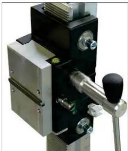
natural_image
Close-up of a mechanical device with black and metallic components, no visible text or symbolsMove the machine holder upwards until it locks into place.
Use the turnstile to open the mounting plate lock.
Remove it and connect it to the core drilling machine as described below.
The scope of delivery includes a mounting plate, a 10 mm key and
four M8 x 25 hexagon socket screws. The mounting plate is placed on the machine with the key and secured with the four screws.
Pay attention to the mounting direction.
Insert the core drill with the attached mounting plate into the drill rig and lock it with the turnstile (see picture above).

The operating instructions and the associated safety instructions must be strictly observed when operating the core drilling machine!
Operations
In order to operate the tool safely, please observe the following notes:
Details of the work area
- Keep the work area free of everything which could obstruct operations.
■ Provide for adequate illumination of the work area. - Adhere to the regulations concerning the power connection.
- Lay the power cable in such a way that any damage by the drill can be avoided.
■ Make sure to always keep the work area in view and to be able to reach all necessary operating elements and safety installations. - Keep other persons away from your work area in order to avoid accidents.
Space requirements for operating and maintenance
Whenever possible, keep a free space for operating and maintenance of about 2 m around the drill position, so that you can work safely and have immediate access in case of a failure.
Drilling
Inclined drilling
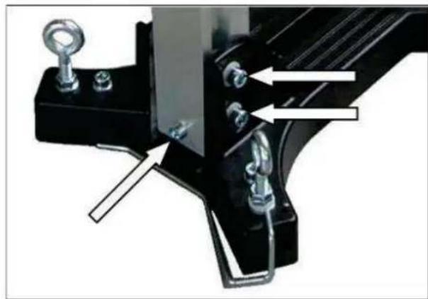
natural_image
Close-up of a mechanical component with mounting holes and a bracket, showing no visible text or symbols.- Remove the screw that locks the drill column at 90°.
- Then loosen the two M10 hexagon socket screws using the SW8 wrench provided.
■ Move the column to the desired angle. Tighten the two screws again.
■ After drilling, return the co-lumn to the 90° position and lock it in place with the screw.
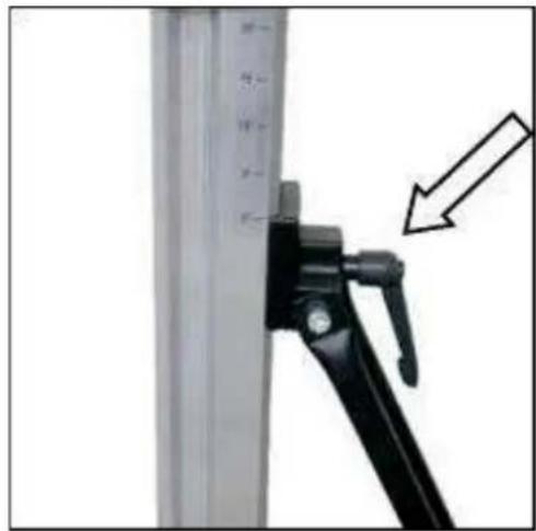
natural_image
Close-up of a mechanical lever with a black handle and arrow indicating motion (no text or symbols visible)On the BST 300, the toggle screw located on the support must also be loosened.
The scale on the tooth column makes it easier to set the drilling angle, which greatly simplifies the work.
At the beginning, it is important to drill very slowly, as only a fraction of the cutting surface of the core bit engages with the material. Drilling too quickly or with too much pressure can cause the core bit to slip.
An extension may be required for the core bit in order to achieve the full drilling depth!
Demounting the Core Drill Unit

- Move the machine holder with the core drilling machine upwards until it locks into the end position.
- Remove the drill bit.
■ Loosen the wing nut (F). (see section on fastening) - Hold the drill stand firmly in place while doing so!
■ Remove the drill stand. - Unscrew the quick-release screw (D). (see section on fastening)
Care and Maintenance
- Always keep the drill rig clean, especially the column with the toothing and the 4 sliding pieces in the machine holder.
- In order to allow the free movement of the pinion shaft, it should be slightly lubricated.
- In order to achieve a good performance of the drill rig, the 4 sliding pieces in the machine holder have to move along the column without slackness.
Attention:
After every tenth drilling you should check if the sliding pieces have got loose-fitting due to drilling vibration.
If the position should have changed, it can be readjusted as follows:
natural_image
Mechanical device with labeled components and directional arrows (no readable text or symbols)- Using a 17 mm open-end wrench, loosen the lock nut on the hexagon socket screw.
- Using an 8 mm hexagon key, adjust the hexagon socket screws and thus the position of the pressure pieces relative to the column.
- Tighten the lock nut again and check that the machine holder moves smoothly on the guide column of the diamond drill stand.
Warranty
In accordance with our General Terms and Conditions of Delivery, a warranty period of 12 months applies to material defects in business transactions with entrepreneurs (proof by invoice or delivery note).
This does not include damage resulting from natural wear and tear, excessive use or improper handling. Damage resulting from material or manufacturing defects will be repaired free of charge by repair or replacement. Complaints can only be accepted if the device is returned to the supplier or an Eibenstock authorised repair shop in its unassembled state.
EU - Declaration of Conformity
It is necessary that the machine (f. e. EBM 250/2 RP) used in this drill rig comply with the requirements which are described in the specifications of the drill rig (f. e. drilling diameter, fixture of the motor).
We declare that this unit has been designed in compliance with 2006/42/EC. This unit must not be put into service until it was established that the Power Tool to be connected to this unit is in compliance with 2006/42/EC (identified by the CE-marking on the Power Tool).
natural_image
Close-up of a mechanical device with black and metallic components, no visible text or symbolsnatural_image
Close-up of a mechanical component with mounting holes and a bracket, showing no visible text or symbols.natural_image
Close-up of a mechanical lever with a black handle and arrow pointing to a measurement scale (no text or symbols visible)natural_image
Mechanical device with lever and adjustment knob, no visible text or symbolsnatural_image
Six circular icons representing different person features: headphones, glasses, hat, hand gesture, boots, and a boot (no text or symbols)De Boorinstallatie Verankeren
Verankering in beton d.m.v. geleidepinnen
natural_image
Close-up of a mechanical device with black and metallic components, no visible text or symbolsnatural_image
Close-up of a mechanical clamp or bracket component with mounting hardware and mounting holes (no visible text or symbols)natural_image
Close-up of a black mechanical lever with a pointer and arrow indicating measurement or adjustment (no text or symbols visible)natural_image
Mechanical device with lever and adjustment knobs, no visible text or symbolsnatural_image
Six circular icons representing different workplace safety or safety symbols (head, glasses, hat, hand, boot, and boots), no text or labels present.natural_image
Close-up of a mechanical device with black and metallic components, no visible text or symbolsnatural_image
Mechanical component with mounting holes and a bracket, showing no visible text or symbolsnatural_image
Close-up of a mechanical device with a vertical scale and an arrow pointing to it (no visible text or symbols)natural_image
Mechanical device with labeled components and directional arrows (no readable text or symbols)natural_image
Close-up of a mechanical device with black and metallic components and a metal lever handle (no visible text or symbols)natural_image
Mechanical assembly diagram showing a bracket with mounting holes and a spring, no text or symbols presentnatural_image
Close-up of a black mechanical clamp securing a vertical metal frame with a scale ruler, no visible text or symbols.natural_image
Mechanical device with labeled parts and directional arrows (no readable text or symbols)natural_image
Close-up of a mechanical device with black and metallic components, no visible text or symbolsnatural_image
Mechanical component with mounting bracket and bolts, no visible text or symbolsnatural_image
Close-up of a black mechanical lever handle attached to a vertical metal frame, with an arrow pointing to the lever (no text or symbols visible)natural_image
Mechanical device with labeled components and directional arrows (no readable text or symbols)natural_image
Six circular icons representing different workplace safety or equipment symbols (head, glasses, hat, hand, boot, and boots), no text or labels present.natural_image
Close-up of a mechanical device with black and metallic components and a black lever handle (no visible text or symbols)natural_image
Mechanical component with mounting bracket and bolts, no visible text or symbolsnatural_image
Close-up of a black mechanical lever with a white vertical bar and arrow pointing to the handle (no text or symbols visible)natural_image
Mechanical device with labeled parts and directional arrows (no readable text or symbols)natural_image
Six circular icons representing different types of protective gear and objects, including headphones, sunglasses, a hat, hand, boots, and a boot (no text or symbols)natural_image
Close-up of a mechanical device with black and metallic components, no visible text or symbolsnatural_image
Close-up of a mechanical clamp or bracket component with metallic fittings and mounting holes (no visible text or symbols)natural_image
Close-up of a black mechanical lever with a directional arrow pointing to a vertical panel (no text or symbols visible)natural_image
Mechanical device with labeled parts and directional arrows indicating motion or assembly (no readable text or symbols)Your specialist dealer


- Wichtige Hinweise
- Nur für EU-Länder
- Important Instructions
- Technical Data
- Supply
- Intended use
- Electrical Connection
- Attention!
- Water Connection
- Changing Gears
- Warning!
- Drill bits
- Drill Bit Changing
- Using the Drilling Unit
- Information on the place of use
- Space required for operation and maintenance
- Preparation
- Fastening of the Drill Rig
- Caution! Not for wall and ceiling drilling!
- Drilling
- Vertical drilling
- Angular drilling
- Drill bit extension
- Overload Protection
- Safety clutch
- Segmental fracture
- After drilling
- Removing the drill core from a blind hole
- Care and Maintenance
- Before the beginning of the maintenance or repair works you have to disconnect the plug from the mains!
- Environmental Protection
- Raw material recycling instead of waste disposal
- Only for EU countries
- Noise Emission / Vibration
- Wear hearing protection!
- Cut-off brushes
- In Case of Malfunction
- Warranty
- EU - Declaration of Conformity
- GB - Declaration of Conformity
- FRANÇAIS
- Kun for EU-lande
- PORTUGUÊS
- Notas importantes
- Důležité poznámky
- Tylko dla krajów EU
- ΕΛΛΗΝΙΚΑ
- DEUTSCH
- Technical specifications
- Scope of delivery
- Application for Intended Purpose
- Use
- After each new adjustment, check that the screws are tight so that the drill stand can be used safely.
- Attaching the turnstile
- Fastening by means of quick action bracing unit
- Caution!
- Fixing the Core Drill Motor
- Setting up the mounting plate
- The operating instructions and the associated safety instructions must be strictly observed when operating the core drilling machine!
- Operations
- Details of the work area
- Space requirements for operating and maintenance
- Inclined drilling
- Demounting the Core Drill Unit
- Attention:
- De Boorinstallatie Verankeren
Brand : Eibenstock
Model : DBE 250 R
Category : Electric drill