
DSE 162 - Electric drill Eibenstock - Free user manual and instructions
Find the device manual for free DSE 162 Eibenstock in PDF.

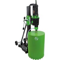
| Product type | Electric diamond core drill |
| Brand | Eibenstock |
| Model | DSE 162 |
| Rated voltage | 230 V ~ |
| Power consumption | 2200 W |
| Amperage | 10.0 A |
| Frequency | 50/60 Hz |
| No-load speed | 0-1100 rpm |
| Impact frequency | max. 22000 min⁻¹ |
| Tool holder | 1 ¼" UNC female / R ½" female |
| Drilling diameter (concrete) | 82-162 mm (up to 202 mm with stand) |
| Weight (core drill) | approx. 6.7 kg |
| Protection class | I |
| Protection rating | IP 20 |
| Interference suppression | EN 55014 and EN 61000 |
| Package contents | Core drill, 2 open-ended wrenches (SW32 and SW41), instruction manual, transport case |
| Included accessories | Drill stand BST 162H, diamond core bits ∅82/102/132/162 mm (dry drilling), copper ring, vacuum cleaner ESS 35 MP (optional) |
| Maintenance | Clean after use, grease the shaft, change engine oil every 150 h, check carbon brushes every 200 h |
| Safety | Wear PPE (goggles, helmet, gloves, shoes, ear protection), disconnect before maintenance, do not use in wet environments |
| Warranty | 12 months for businesses (on invoice), covers manufacturing defects, excludes abnormal use |
Frequently Asked Questions - DSE 162 Eibenstock
User questions about DSE 162 Eibenstock
0 question about this device. Answer the ones you know or ask your own.
Ask a new question about this device
Download the instructions for your Electric drill in PDF format for free! Find your manual DSE 162 - Eibenstock and take your electronic device back in hand. On this page are published all the documents necessary for the use of your device. DSE 162 by Eibenstock.
USER MANUAL DSE 162 Eibenstock
natural_image
Green hexagonal logo with stylized letter 'E' (no text or symbols)Original Instructions....14 - 25
natural_image
EIBENSTOCK electric drill putter with black and green casing (no visible text or symbols)natural_image
Mechanical device with black handle and threaded shaft, showing bidirectional arrow indicating rotation (no text or symbols)natural_image
Close-up of a green and black electric drill press tool with a pull rod and mechanical base (no visible text or symbols)natural_image
Close-up of a black circular device with a white T-shaped symbol and a metallic screw, mounted on a green surface (no text or symbols visible)natural_image
Close-up of a black circular device with white markings on a green background (no visible text or symbols)natural_image
Symbol of a trash bin crossed with diagonal lines, representing waste sorting or disposal (no text or labels)Nur für EU-Länder
natural_image
Close-up of a camera control panel with three buttons and a white arrow pointing to the button (no text or symbols visible)Frank Markert
Head of Engineering
Important Instructions
Important instructions and warning notices are put on the machine by means of symbols:

Before you start working, read the operating instructions of the machine.

Work concentrated and carefully. Keep your work-place clean and avoid dangerous situations.

In order to protect the user, take precautions.
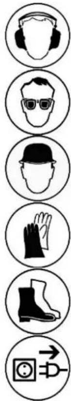
In order to protect yourself, implement the following actions:

Use ear protection

Wear safety goggles

Wear a helmet

Use protective gloves

Wear protective boots
Warning of dangerous voltage

Warning of hot surface
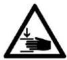
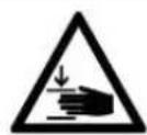
Danger of being crushed

Danger of being ripped or cut
Technical Data
Percussion Diamond Core Drill ESD 162
| Nominal voltage 230 V ~ | |
| Power drain 2200 W | |
| Rated current 10,0 A | |
| Frequency: 50/60 Hz | |
| No-Load speed: | 0-1100 rpm |
| Percussion frequency: | max. 22000/min |
| Bit holder: 1 1⁄4“ UNC - R1⁄2” i | |
| Max. drilling diameter concrete: | 82-162 mm (brickwork up to 202mm) |
| Protection class: | I |
| Degree of protection: | IP 20 |
| Weight: | approx. 6.7 kg |
| Order No. | 03E25000 |
Interference suppression acc.to:
EN 55014 and EN 61000
Available add-ons:
| Item | Order No. |
| Diamond drill rig BST 162H | 0963W000 |
| Fastening set concrete/stone | 35720000 |
| Diamond drill bit dry ∅ 82, 102, 132 and 162mm | |
| Copper ring for easier drill bit removal | 35450000 |
| Wet/dry deduster ESS 35 MP | 09931000 |
For further information about our products and our wide range of accessories please see: www.eibenstock.com.
Supply
Diamond core drill with 2 open-end wrench (SW32 and SW41) and instruction manual in transport case.
Application for Indented Purpose
The diamond core drill ESD 162 is indented only for professional use and may be used only by instructed personnel.
With an appropriate drill bit, the tool can be used for drilling of concrete, stone, bricks, sand-lime bricks and pore concrete.
For drilling jobs with diameters above 132mm (102mm in reinforced concrete) it is a must to use a suitable drill rig.
The machine may be used exclusively in conjunction with a vacuum cleaner of dust category M.
Concrete and reinforced concrete are to be drilled only with soft impact.
The user alone is liable for damage caused by improper use.

Safe use of the tool is only possible if the user had studied the instruction manual and safety instructions completely and is strictly following the instructions contained therein. Additionally, the general safety instructions of the leaflet supplied with the tool must be observed. Prior to the first use, the user should absolve a practical training. Save all warnings and instructions for future reference.
If the mains cable gets damaged or cut during the use, do not touch it, but instantly pull the plug out of the socket. Never use the tool with damaged mains cable.
Prior to drilling in walls and ceilings, check them for hidden cables, gas and water pipes and other media. Check the working area, e. g. using a metal detector. Prior to the start of your work, consult a statics specialist to determine the exact drilling position. If drilling through ceilings, secure the place below, because the may fall downward.

Do not expose power tools to rain or wet conditions.
Water entering a power tool will increase the risk of electric shock.
- Do not use the tool in an environment with danger of explosion.
- Do not use the tool standing on a ladder.
- Do not drill into asbestos-containing materials.
- Do not carry the tool at its cable, and always check the tool, cable and plug before use. Have damages only repaired by specialists. Insert the plug into the socket only when the tool switch is off.
■ Modifications of the tool are prohibited. - Unplug the tool and make sure that the switch is off if the tool is not under supervision, e.g. during preparation and take-down works, at power failures, for insertion or mounting accessories.
- Unplug the tool if it stops for any reason. So you avoid sudden starts in unattended condition.
- Don't use the machine if a part of the housing is damaged or in case of damages on the switch, the cable or plug.
- Always lead the mains and extension cables as well as the dedusting hose from the tool to the back.
- Electrical tools have to be inspected visually by a specialist in regular intervals.
■ After interruption of your work, restart the tool only after having made sure that the drill bit is moving freely. - Keep the handles dry, clean, and free of oil and grease.
- Do not touch rotating parts.
- Persons under 16 years are not allowed to use the tool.


- During use, the user and other persons standing nearby have to wear suitable goggles, helmets, ear protectors, dust mask, protective cloves and boots.
- The tool may be used only in two-hand operation or with the drill rig. During manual operation, always hold the tool with both hands and be fall-safe. Consider the tool's reaction torque in case of blocking.
- Always work in a carefully considered way and do not use the tool if you are lacking consideration.
- Hold power tool by insulated gripping surfaces, when performing an operation where the cutting accessory may contact hidden wiring or its own cord. Cutting accessory contacting a “live” wire may make exposed metal parts of the power tool “live” and could give the operator an electric shock.
- During manual operation, work with a special circumspection when dry drilling with dimensions between 102 and 132mm!
For further safety instructions, see the enclosure.
Electrical Connection
The ESD 162 is made in protection class 1.
Prior to putting the tool into operation, check the mains voltage for conformity with the requirements of the tool's nameplate.
Voltage variations between + 6 % and - 10 % are permissible.
Use only extension cable with sufficient cross-section (min. 2,5 mm ^2 ). A cross-section which is to small could lead to excessive power loss and to overheating the motor and the cable.
Recommended minimum cross sections and maximum cable lengths
| Mains voltage | Cross section in sq. mm | |
| 1.5 | 2.5 | |
| 110V | 20 m | 40 m |
| 230V | 50 m | 80 m |
The tool includes a start-up speed limiter to prevent fast expulsion fuses from unindented responding.
Additional Handle
natural_image
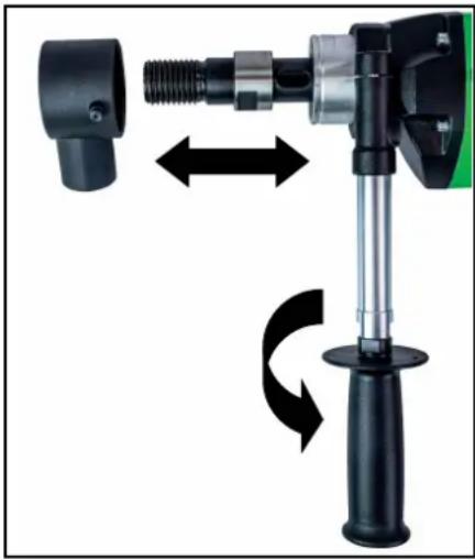
Mechanical device with black plastic housing and mechanical lever, showing bidirectional rotation arrows (no text or symbols)For manual drilling, the ESD 162 may be used only together with its additional handle which comes with the tools.
Place it on the gearing collar from the front and fix it by turning the handle in direction of the arrow.
Before mounting or dismounting the handle clamp, the dust exhaustion must be disconnected from the gearing collar.
Switching ON and OFF
Short-time operation
ON: Press the ON/OFF switch
OFF: Release the ON/OFF switch
Long-time operation
ON: Keeping the ON/Off switch pressed, push in the arrestor button.
OFF: Press and release the ON/OFF switch again.

Attention!
Use the arrestor button only during operation with drill rig. Its use during manual operation is not allowed.
If the machine stops for any reason or due to power failure, immediately release the arrestor button by pressing the ON/OFF switch.
Dust Exhaustion
natural_image
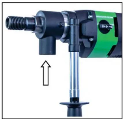
Close-up of a green and black electric drill press tool with a pull rod and mechanical base (no text or symbols visible)Dust which occurs during your work is hazardous to health. That is why it is advisable to use a deduster (Dust class M) and to wear a dust mask on dry drilling. Place the adapter for the dedusting unit onto the tool's connector and turn into the direction of the arrow up to the stop. As a suitable wet/dry deduster, our DSS 35 M iP is available as add-on. The use of a dedusting system is also a prerequisite for optimal cutting performance of the bit (air cooling).
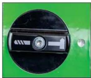
Engaging and Disengaging of the percussion
The machine is equipped with mechanical soft impact for drilling in hard materials, such as concrete and hard sand-lime bricks.
This can be enabled or disabled as follows.
natural_image
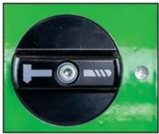
Close-up of a black circular switch with a white T-shaped symbol and a metallic connector, mounted on a green background (no text or symbols visible)Drill symbol on mark
- drilling without soft impact
natural_image
Close-up of a black circular device with white directional arrows and a central button, mounted on a green background (no text or symbols visible)Hammer symbol on mark
- drilling with soft impact
Manual Drilling
natural_image
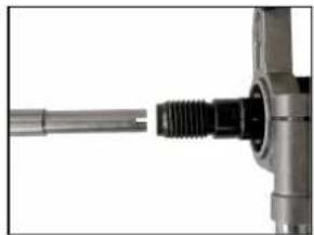
Close-up of a mechanical component with threaded shaft and flange (no visible text or symbols)Insert the centering point so that the recesses in the centering point latch on the catches of the working spindle.
Fix the required dry drill bit on the working spindle.
Always deactivate the soft impact to start drilling!
Check for appropriate gear selection. Operate the ON/OFF switch and drill until the segments are approximately 5 mm in the material. Remove the centering point. To drill in concrete, activate the soft impact.
Refix the drill bit to the existing groove and complete your drilling.
Take care that the drill bit is not out of line.
Advance the tool according to bit diameter and machine power. Observe the LED in the handle.
If it lights red, reduce your pressing force.
In case the bit gets jammed, to not dry to release it by switching the tool on and off. This would cause premature wearing of the safety clutch. Switch the tool off immediately and unfix the drill bit by turning to the left or right using an appropriate open-end wrench. Cautiously pull the tool out of the borehole.
Drill Bits
Diamond drill bits with a 1 14 " UNC female thread can be screwed directly onto the working spindle.
Use only appropriate drill bits for the material to be drilled in. You can protect your tool by using only well balanced drill bits without deformation.
Make sure that the diamond segments have sufficient cutting clearance towards the bit body.
Changing Drill Bits


Attention!
When you use or sharpen the machine, it might heat up enormously. You could burn your hands or get cut or ripped by the segments. Therefore, always use protective gloves when changing the drill bit.
The drilling spindle has a right-hand thread.
To ease screwing on and off, always use a SW 32 open-end wrench at the drilling spindle. Never use a hammer, because this may damage both the drill bit and the tool. Some water-resistant grease on the drilling spindle threat or a copper ring between spindle and drill bit will simplify removal of the drill bit.
After Drilling
When you have finished drilling:
■ Pull the drill bit out of the hole.
- Turn the motor off.
Removal of the core when it sticks in the drill bit:
- Separate the drill bit from the motor (if possible).
- Put the drill bit in a vertical position.
- Knock carefully on the pipe by using a wooden hammer shank till the drilling core slips out. Never throw the drill bit against a wall by force or set about it with tools, such as hammer or jaw wrench. Otherwise, the pipe could go out of shape and neither the drilling core can be extracted nor the drill bit is reusable.
Removal of the core by blind holes:
Break off the core with a cotter or lever, or in pieces. Lift the core out with appropriate tongs or drill a hole with a dowel in the core, screw an eyebolt in and pull the core out.
Rig Drilling
The drill rig does not belong to the supply.
For this purpose, please refer to the drill rig's operating instructions.
Overload Protection
To protect the user, motor and drill bit, the ESD 162 is equipped with a mechanical, electrical and thermal overload protection.
Mechanical: In the event of a sudden jamming of the drill bit, the machine's kickback is limited to a reaction torque controllable by the operator by means of a slip clutch.
Electrical: To warn the user against overstressing the tool by applying to high an advance force, the handle includes a LED as a overload indicator. It does not light during idle run or at normal load. At overload, it lights red. In that case the tool most be stress-relieved. In case of longer non-observation of the rad indication, the electronics will independently switch the tool off. After relieving be switching the tool off and on, the work can be continued as normal.
Safety Clutch
The safety clutch should absorb shock and excessive stress. It is an aid and not an absolute protection. Therefore you have to handle and drill carefully. To keep it in good condition, the clutch should slip for a very short time (max. 2 seconds) in each case only. Slipping for longer periods destroys the safety clutch. After excessive wearing the clutch has to be renewed by an authorized service shop.
Care and Maintenance
Before the beginning of the maintenance- or repair works you have to disconnect plug from the mains.
Repairs may be executed only by appropriately qualified and experienced personnel. After every repair, the unit has to be checked by an electrical specialist. According to its design, the tool requires a minimum of care and maintenance. However, the following maintenance works and component checks have to be performed in regular intervals:
- Clean the tool after completion of your work. Apply some grease onto the drilling spindle thread. The ventilation slots must always be clean and unclogged. Make sure that now water gets into the tool during cleaning.
■ After the first 150 hours of operation, the gearing oil must be changed.
Gearing oil changes bring about an essential increase of the tool's lifetime.
■ After approx. 250 hours of operation, the carbon brushes must be checked and, if necessary, be replaced by an authorized specialist (use only original carbon brushes). - Once per quarter of a year, an electrical specialist should check the switch, cable and plug.
Our after-sales service responds to your questions concerning maintenance and repair of your product as well as spare parts.
EIBENSTOCK's application service team will gladly answer questions concerning our products and their accessories.
Environmental Protection

Raw material recycling instead of waste disposal
To avoid damages in transit, the tool is supplied in a sturdy packing. The packing as well as the tool and its accessories are made of recyclable materials which enable environmentally friendly and sortwise disposal by the local reception points.
Only for EU countries

natural_image
Symbol of a trash bin crossed with no text or numbers, representing waste sorting or disposal (no text present)Do not dispose of electric tools together with household waste material!
In observance of European Directive 2012/19/EU on waste electrical and electronic equipment and its implementation in accordance with national law, electric tools that have reached the end of their life must be collected separately and returned to an environmentally compatible recycling facility.
Noise Emission / Vibration
Measured sound values determined according to EN 62841-2-1.
Typically the A-weighted noise levels of the product are:
Sound pressure level L_pA 95 dB(A)
Sound power level L_wA 106 dB(A)
Uncertainty K 3 dB

Wear ear protectors!
Vibration total values a_h and uncertainty K determined according to EN 62841-2-1:
Vibration emission value a_h 13,5 m/s ^2
Uncertainty K 0,3 m/s ^4
The declared vibration emission level represents the main applications of the tool. However if the tool is used for different applications, with different accessories or poorly maintained, the vibration emission may differ. This may significantly increase the exposure level over the total working period. An estimation of the level of exposure to vibration should also take into account the times when the tool is switched off or when it is running but not actually doing the job. This may significantly reduce the exposure level over the total working period. Identify additional safety measures to protect the operator from the effects of vibration such as: maintain the tool and the accessories, keep the hands warm, organisation of work patterns.
Dust Protection
Dust from material such as paint containing lead, some wood species, minerals and metal may be harmful. Contact with or inhalation of the dust may cause allergic reactions and/or respiratory diseases to the operator or bystanders. Certain kinds of dust are classified as carcinogenic such as oak and beech dust especially in conjunction with additives for wood conditioning (chromate, wood preservative). Material containing asbestos must only be treated by specialists.
- Where the use of a dust extraction device is possible it shall be used.
- To achieve a high level of dust collection, use industrial vacuum cleaner ESS 35 MP for wood and/or minerals together with this tool.
■ The work place must be well ventilated. - The use of a dust mask of filter class P2 is recommended.
Trouble Shooting
In case of breakdown, switch the motor off and disconnect it from the power. Repairs of the electrical parts may only be performed by an authorised service specialist.
| Error | Possible Cause | Error Recovery |
| Machine does not work. | mains current supply interruptedline cord or plug damagedswitch damaged | plug in another electric appliance and check the functioninghave it checked by an electric specialist and replaced if necessaryhave it checked by an electric specialist and replaced if necessary |
| motor runs, drill bit does not rotate | gearbox damaged have the tool | repaired by an authorised service workshop |
| drilling speed too slow | drill bit damageddrill bit polished | check if drill bit is damaged and replace it if necessarysharpen the drill bit with a sharpening stick while using the flush |
| motor shuts down the | tool stopsoverload protection of the motor has reactedcarbon brushes are worn out - auto-stop brush switch off | lead the tool in a straight mannerdischarge the tool and restart it by pressing the switch a couple of timesboth brushes must be replaced with original brushes by an electrical specialist |
Auto-stop brushes
In order to protect the motor, this power tool is equipped with auto-stop brushes. When the carbon brushes are worn out, the machine switches itself off. In this case both brushes must be replaced at the same time with original brushes by an electrical specialist.

natural_image
Close-up of a camera key with three buttons and a white arrow pointing to the button (no text or symbols visible)In addition there is a service indicator on the operating handle which indicates in advance that the machine is about to shut down due to worn carbon brushes. After the indicator lights up, you can use the tool for approximately 1 day. Then the carbon brushes should be replaced.
Warranty
According to the general supply conditions for business dealings, suppliers have to provide to companies a warranty period of 12 months for redhibitory defects. (To be documented by invoice or delivery note). Damage due to natural wear, overstressing or improper handling are excluded from this warranty. Damages due to material defects or production faults shall be eliminated free of charge by either repair or replacement.
Complaints will be accepted only if the tool was returned in non-dismantled condition to the manufacturer or an authorized Eibenstock service centre.
EU - Declaration of Conformity
We declare under our sole responsibility that the product described under “Technical Data” is in conformity with the following standards or standardization documents:
EN 62841-1:2023-03
EN 62841-2-1:2023-06
EN 55014-1:2020-12
EN 55014-2:2022-10
EN 61000-3-2:2023-10
EN 61000-3-3:2023-02
according to the provisions of the directives 2011/65/EU, 2014/30/EU, 2006/42/EG
Technical file (2006/42/EC) at:
Frank Markert
Head of Engineering
GB - Declaration of Conformity
We declare as the manufacturer under our sole responsibility that the product described under “Technical Data” fulfills all the relevant provisions of the following regulations S.I. 2008/1597 (as amended), S.I. 2017/1206 (as amended), S.I. 2012/3032 (as amended) and that the following designated standards have been used:
BS EN 62841-1:2023-03
BS EN 62841-2-1:2023-06
BS EN 55014-1:2020-12
BS EN 55014-2:2022-10
BS EN 61000-3-2:2023-10
BS EN 61000-3-3:2023-02
Technical file (S.I. 2008/1597) at:
Lothar Lässig
General Manager
Frank Markert
Head of Engineering
26.11.2024
Subject to change without notice.
Attention: Voltage dangereux
Attention: Surface chaude
natural_image
Mechanical device with black handle and threaded shaft, showing bidirectional motion arrows (no text or symbols)natural_image
Close-up of a green and black electric drill press tool with a pull rod and threaded shaft (no visible text or symbols)natural_image
Close-up of a black circular switch with a white T-shaped symbol and a metallic screw, mounted on a green surface (no text or numbers visible)natural_image
Close-up of a black circular device with a white handle and indicator lights, mounted on a green background (no visible text or symbols)natural_image
Close-up of a metallic mechanical component with threaded shaft (no visible text or symbols)natural_image
Symbol of a trash bin crossed with diagonal lines, representing waste sorting or disposal (no text or labels)natural_image
Close-up of a black handheld device with circular buttons and a white arrow pointing to a button (no readable text or symbols)Frank Markert
Head of Engineering
natural_image
Mechanical device with black components and directional arrows indicating motion (no text or symbols)natural_image
Close-up of a green and black electric drill press tool with a pull rod and mechanical base (no text or symbols visible)natural_image
Close-up of a black circular device with a T-shaped symbol and a metallic connector, set against a green background (no text or symbols visible)natural_image
Close-up of a green industrial component with a black circular dial and white directional arrow (no text or symbols visible)natural_image
Close-up of a metallic mechanical component with threaded end (no visible text or symbols)natural_image
Symbol of a trash bin crossed with no text or labelsSolo per i paesi UE
natural_image
Close-up of a camera control panel with three buttons and a white arrow pointing to the button (no text or symbols visible)Frank Markert
Head of Engineering
natural_image
Mechanical device with black handle and threaded shaft, showing bidirectional arrow indicating rotation (no text or symbols)natural_image
Close-up of a green and black electric drill bit with a pull rod and mechanical lever (no text or symbols visible)natural_image
Close-up of a black circular device with a white T-shaped symbol and a metallic connector, set against a green background (no text or symbols visible)natural_image
Close-up of a black circular device with white arrows and a circular button, mounted on a green background (no visible text or symbols)natural_image
Close-up of a mechanical component with a threaded shaft and flange (no visible text or symbols)natural_image
Symbol of a trash bin crossed with no text or labelsnatural_image
Close-up of a black handheld device with four circular buttons and a white arrow pointing to a button (no readable text or symbols)Frank Markert
Head of Engineering
DANSK
natural_image
Mechanical device with threaded shaft and lever mechanism, shown in two different orientations (no text or symbols)natural_image
Close-up of a green and black electric drill press tool with a pull rod and mechanical base (no text or symbols visible)natural_image
Close-up of a black circular mechanical component with a T-shaped symbol and a metallic screw, set against a green background (no text or symbols visible)natural_image
Close-up of a black circular device with a white connector and a circular button, mounted on a green background (no visible text or symbols)natural_image
Pure electrical circuit lines without any symbolsnatural_image
Symbol of a trash bin with no text or labelsKun for EU lande
natural_image
Close-up of a black electronic device's control knob with a white arrow pointing to it, no visible text or symbols.Lothar Lässig
General Manager
26.11.2024
Frank Markert
Head of Engineering
Ihr Fachhändler Your distributor Votre marchand spécialisé Il vostro rivenditore specializzato Uw distributeur Din forhandler
EIBENSTOCK
Vakuum Technik
D Originalbetriebsanleitung...... 2 – 10
GB Original instructions.... 11 – 18
F Notice originale.... 19 – 26
IT Istruzioni d'uso originali.... 27 – 35
NL Oorspronkelijke gebruiksaanwijzing...... 36 – 43
ES Manual de instrucciones original.... 44 – 52
natural_image
Green and black industrial machine with handle and base (no visible text or symbols)natural_image
Close-up of a green mechanical clamp or fixture with a hand adjusting a black tool (no visible text or symbols)
natural_image
Green mechanical clamp device with labeled parts (1 and 2), no visible text or symbols beyond labelsnatural_image
Close-up of a mechanical clamp or bracket with a metallic wire and a cross mark, no visible text or symbolsnatural_image
Close-up of a green industrial mechanical component with threaded shaft and mounting bracket (no visible text or symbols)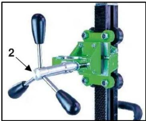
natural_image
Close-up of a green mechanical clamp or fixture with four black-handled handles and a labeled component (no text or symbols visible)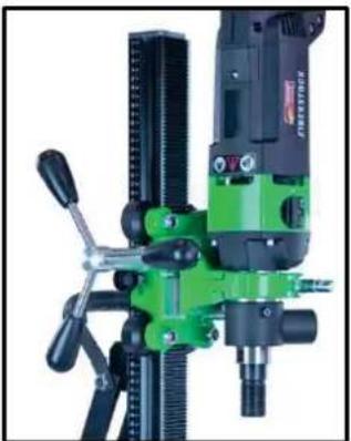
natural_image
Close-up of a green and black industrial milling machine with no visible text or symbols
natural_image
Close-up of a black mechanical clamp or bracket component with mounting holes and a numbered annotation (1) pointing to a specific part.
natural_image
Close-up of a bicycle climbing mechanism with labeled component '2' (no text or symbols on the mechanism itself)natural_image
Close-up of a green industrial machine component with a central screw and two bolts, showing no visible text or symbols.
natural_image
Close-up of a green industrial machine with dual gears and a dial, showing no visible text or symbols.
natural_image
Close-up of a mechanical clamp or bracket assembly with green and metallic components (no visible text or symbols)Important Instructions
Warning symbols:

Warning: general precaution
Warning: dangerous voltage
Warning: hot surface
Tool, drill bit and rig are heavy
- Caution: risk of squashing
Danger of tearing or cutting
During work you should wear goggles, ear protectors, protective gloves, and sturdy work clothes!
Wear ear protection
Wear safety goggles
Wear protective helmet
Wear protective gloves
Wear protective boots
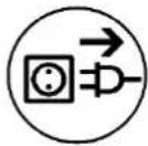
Do disconnect from power before working on the tool!
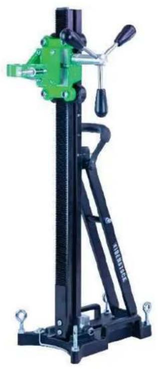
Technical characteristics
| Measures: 460 x 230 x 895 mm | |
| Length of the column / Hub: 860 mm / Weight: 10,5 kg | 650mm |
| Max. drilling diameter 202 mm | |
| Inclination: | 0° bis 45° |
| Locking in top position: Yes | |
| Fixture of the motor: Collar mounting ∅ 60mm | |
| Adaptation to surface | 4 positioning screws / 2 bubble levels |
Available special accessories:
| Item | Order no. |
| Fastening set (concrete) 35720000 | |
| Fastening set (brickwork) 35724000 | |
| Spare dowel 35722000 | |
| Brickwork-dowel 35725000 | |
| Quick action bracing unit 35730000 |
Supply
Diamond drill rig base gasket, fastening screws, Allen screw, turnstile and operating instructions in a cardboard box.
Application for indented purpose
The diamond drill rig BST 162 H is made for diamond core drills with a collar mounting ∅ 60mm (e.g.: ESD 162 or PLD 182.1 NT).
The max. drilling diameter must not exceed 202 mm.
In case of wrong handling or misuse, the producer does not assume any liability.
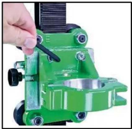
Mounting machine holder
natural_image
Close-up of a green mechanical clamp or fixture with a hand adjusting a black tool (no visible text or symbols)Before using the machine for the first time, the machine holder must be mounted on the carriage. To do this, place the machine holder on the keyway mount on the carriage and screw in the four M8x30 hexagon socket screws firmly using the SW6 Allen key.
Use

After each readjustment always check that the screws are tightly fixed so that safe operating of the drill rig is possible.
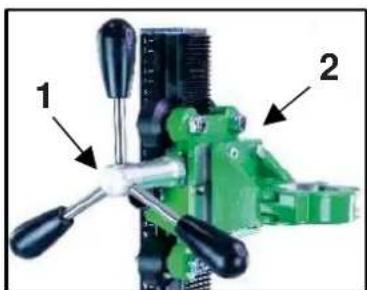
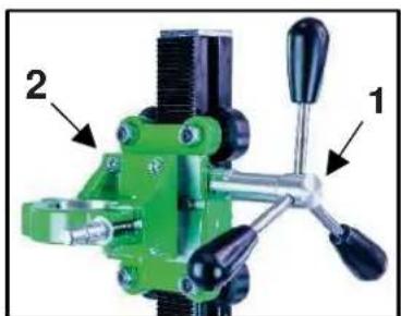
Mounting the turnstile
■ Mount the turnstile (1) on the right or left side of the carriage (2) depending on the work to be performed.
■ Check whether the turnstile (1) is fixed tightly.
natural_image
Green mechanical clamp device with labeled parts (1 and 2), no visible text or symbols beyond labelsFastening of the drill rig
Hole centering indicator:
The drill rig is fitted with a hole centering indicator for easy and precise positioning.
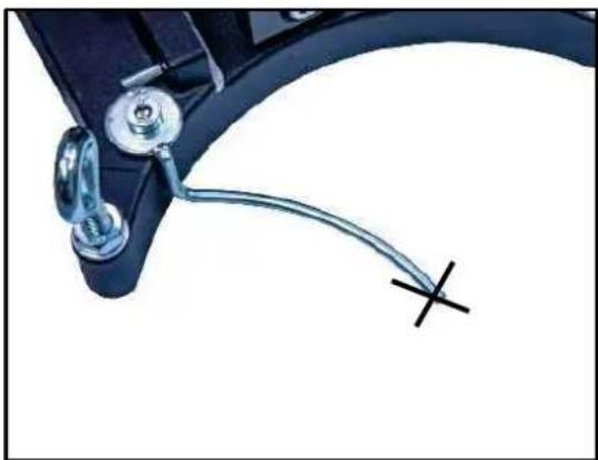
natural_image
Close-up of a mechanical clamp or bracket with a metallic wire and a cross mark, no visible text or symbolsMark the center of the hole to be drilled.
Fully extend the hole centering indicator (see fig.).
Position the drill rig in such a way that the tip or the groove of the indicator points precisely to the hole center mark.
After the drill rig has been fastened, put the hole center indicator back in its original position.
Fastening by means of dowels in concrete
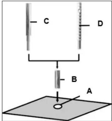
■ Mark the position of the drill holes for the fastening on the surface to be drilled.
- Drill a hole (∅ 16) 50 mm deep (A), into which the dowel M12 (B) is to be placed; insert and secure the dowel with the doweling tool (C).
- Screw the quick action clamping screw (D) into the dowel.
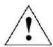
For brickwork, Brickwork-dowels must be used (drillhole - ∅ 18mm).
- Install the drill rig.
- Fix the washer (E) and finally the fastening nut (F) on the quick action clamping screw (D).
- Tighten the fastening nut (F) with a wrench SW 27.
■ Before and after tightening the nut (F), the 4 adjustable screws have to be adjusted in order to adapt the rig to the surface.
Do check whether the drill rig is installed safely and firmly.
Fastening by means of quick action bracing unit
In order to brace the drill rig by means of the quick action bracing unit, the distance to the opposite wall must be between 1.7 m and 3 m.
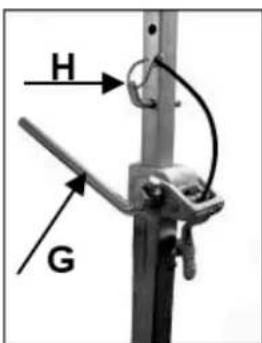
Position the drill rig. Position the quick action bracing unit as close as possible behind the support on the base of the rig. Fix the drill rig by turning the crank (G) clockwise. Secure in position by means of the appropriate bolt (H).
Attention!
It is important, that the drill rig is firmly connected to the surface. If not fixed correctly, injuries to the operator or damages to the drilling unit may be caused.
Uncontrolled movements during drilling will cause the drill bit to hit the surface to be drilled which may lead to a chipping of the segments. The drill bit might also tilt in the bore hole which consequently will damage it.
Fixing the core drill motor

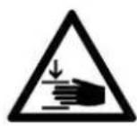

Wear protective gloves! Caution! When mounting the machine, risk of squashing!
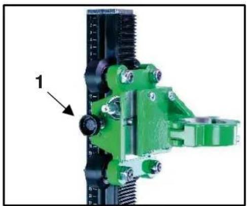
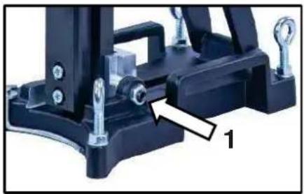
Mounting the core drill machine
Move the machine holder far up and fix it by tightening the screw (1).
Using the feed lever (2), loosen the clamping screw and open the clamp.
Dismantle the additional handle of the machine beforehand.
Place the core drill in the holder and close the clamp using the clamping screw.
Loosen the screw (1) before drilling.
Always lock the carriage when the assembly is not in use.
natural_image
Close-up of a green mechanical assembly with threaded components and a labeled component '1' (no text or symbols on the main structure)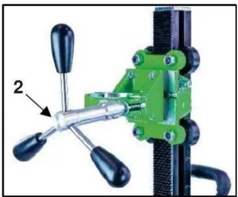
natural_image
Close-up of a green mechanical clamp with four handles and a labeled component (no text or symbols visible)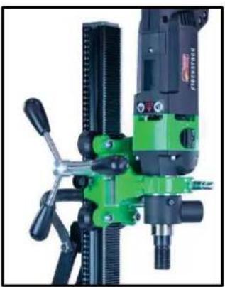
natural_image
Close-up of a green and black industrial milling machine with no visible text or symbols
For operation with the core drill machine you have to attend the operating instructions and the safety indications!
Operations
In order to operate the tool safely, please observe the following notes:
Details of the work area
- Keep the work area free of everything which could obstruct operations.
■ Provide for adequate illumination of the work area. - Adhere to the regulations concerning the power connection.
- Lay the power cable in such a way that any damage by the drill can be avoided.
■ Make sure to always keep the work area in view and to be able to reach all necessary operating elements and safety installations. - Keep other persons away from your work area in order to avoid accidents.
Space requirements for operating and maintenance
Whenever possible, keep a free space for operating and maintenance of about 2 m around the drill position, so that you can work safely and have immediate access in case of a failure.
Drilling
At the beginning, drill very slowly, since the drill bit does only starts cutting with a fraction of the cut surface in the material. If you drill too fast or with too much pressure, the drill bit could get jammed.
Observe the LED in the handle of the ESD 162. If it lights red, reduce your pressing force.
Angled drilling
natural_image
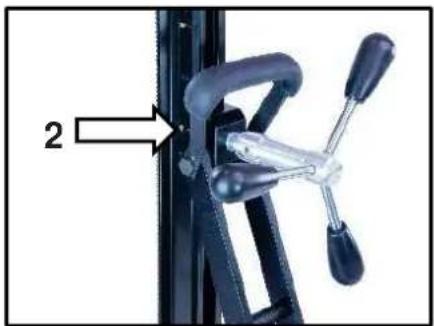
Close-up of a black mechanical clamp or bracket component with mounting screws and a labeled part '1' (no text or symbols on the main subject)■ Loosen the two side screws (1) on the base plate.
■ Loosen the clamp (2) on the support with the help of the feed lever.
- Now turn the column until the desired angle.
- Tighten the 2 screws (1) and the clamp (2) again.
natural_image
Close-up of a mechanical clamp or bracket with a labeled component (no text or symbols visible)The scale on the toothed column makes adjusting the drilling angle easier.
Demounting the core drill unit


- Move the machine holder with the core drill upwards and fix it by tightening the screw (1 - page 14).
■ Remove the drill bit. - Loosen the clamping screw at the machine holder and remove the core drill machine from the drill rig. (see page 14)
■ Loosen the fastening nut (F). (see page 13) While doing so, hold the drill rig firmly!
■ Remove the drill rig.
■ Unscrew the quick action clamping screw (D). (see page 13)
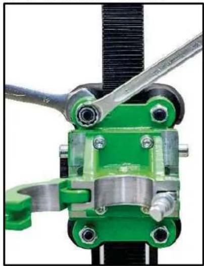
Care and maintenance
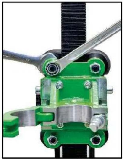
- Always keep the drill rig clean, especially the column with the toothing and the 4 sliding rollers in the machine holder. In order to allow the free movement of the pinion shaft, it should be slightly lubricated.
- In order to achieve a good performance of the drill rig, the 4 sliding rollers in the machine holder have to move along the column without slackness.

Attention!
After every tenth drilling you should check if the sliding pieces have got loose-fitting due to drilling vibration.
If the position has changed, it can be adjusted as follows:
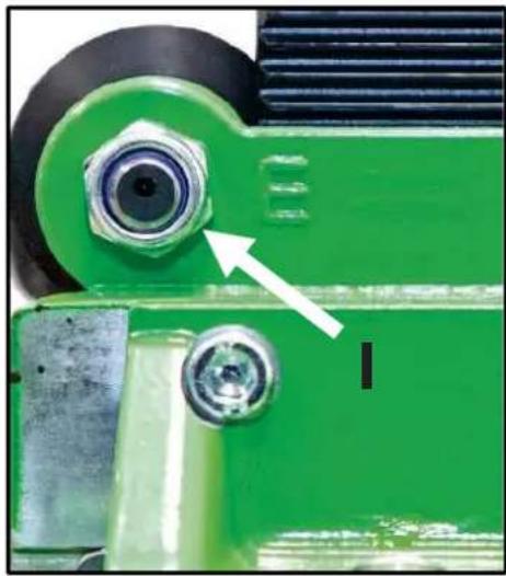
Use an open-ended spanner SW 19 to loosen the nut on the sliding roller marked E.
By slightly turning the nuts (K) with an open-ended spanner SW 19, the pressure of the sliding roller can be adjusted.
After adjusting the sliding roller, the nut (I) must be tightened again.
natural_image
Close-up of a green industrial mechanical component with a white arrow pointing to a circular feature (no text or symbols visible)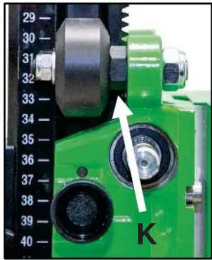
natural_image
Close-up of a mechanical clamp or bracket assembly with green and metallic components (no visible text or symbols)Behaviour at malfunction
Turn off the machine by malfunction and disconnect from the electricity network. Operations on the electrical system of the machine can be executed only by a specialist.
Trouble shooting
| Malfunction | Possible cause | Repair |
| Drill unit has too much play (vibration) | stand has been loose | adjust the wing nut |
| guidance has too much play thrust piece worn | adjust guidance (see page 16) replace the thrust piece | |
| thrust sliding rollers | replace the sliding rollers |
Warranty
According to our general terms of delivery for business dealings, suppliers have to provide to companies a warranty period of 12 months for redhibitory defects. (to be documented by invoice or delivery note).
Damage due to natural wear, overstressing or improper handling are excluded from this warranty.
Damages due to material defects or production faults shall be eliminated free of charge by either repair or replacement.
Complaints will be accepted only if the tool is returned in non-dismantled condition to the manufacturer or an authorized Eibenstock service centre.
EU - Declaration of conformity
It is necessary that the machine (e.g.: ESD 162) used in this drill rig comply with the requirements which are described in the specifications of the drill rig (f. e. drilling diameter, fixture of the motor).
We declare that this unit has been designed in compliance with 2006/42/EC.
This unit must not be put into service until it was established that the Power Tool to be connected to this unit is in compliance with 2006/42/EC (identified by the CE-marking on the Power Tool).
Lothar Lässig
General Manager
16.05.2024
Subject to change without notice.
FRANÇAIS
natural_image
Close-up of a green mechanical clamp or fixture with a hand adjusting a black tool (no visible text or symbols)natural_image
Close-up of a mechanical component with a metallic cable and a cross mark, no visible text or symbolsnatural_image
Close-up of a green mechanical assembly with threaded components and a labeled component (1), no visible text or symbols.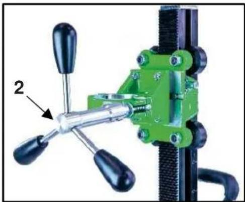
natural_image
Close-up of a green mechanical clamp or fixture with four handles and a labeled component (no text or symbols visible)
natural_image
Close-up of a green and black industrial machine with drill bit and tool handle (no visible text or symbols)
natural_image
Close-up of a black mechanical clamp or bracket assembly with mounting screws and a numbered annotation (1), no visible text or symbols.natural_image
Close-up of a mechanical clamp or bracket with a labeled component (no text or symbols visible)natural_image
Close-up of a green industrial mechanical component with a white arrow pointing to a circular feature (no text or symbols visible)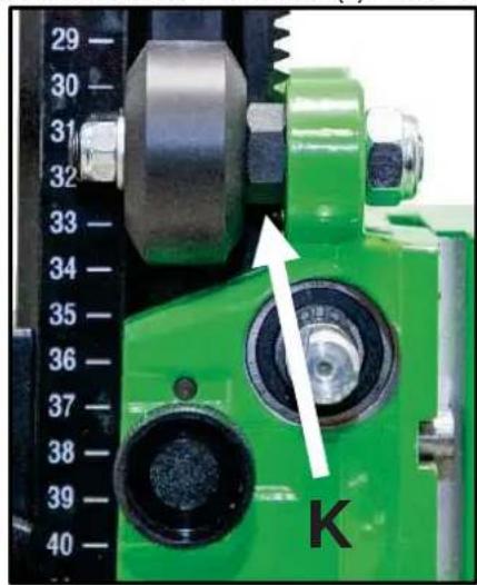
natural_image
Close-up of a mechanical clamp or bracket assembly with green and metallic components (no visible text or symbols)Consignes en cas de panne

Lothar Lässig
General Manager
16.05.2024
natural_image
Close-up of a green mechanical clamp or fixture with a hand adjusting a black tool (no visible text or symbols)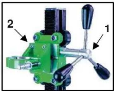
natural_image
Green mechanical clamp device with labeled parts (1 and 2), no visible text or symbols beyond labelsnatural_image
Close-up of a mechanical clamp or bracket with a metallic wire and a cross mark, no visible text or symbolsnatural_image
Close-up of a green mechanical clamp or bracket assembly with threaded components and a labeled component (1), no visible text or symbols.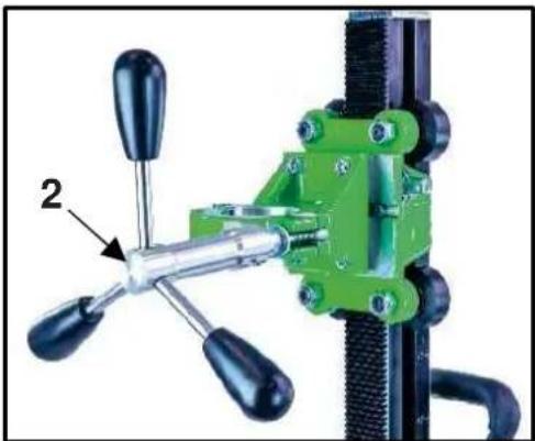
natural_image
Green mechanical clamp device with black handles and a labeled component (no text or symbols visible)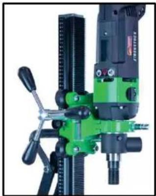
natural_image
Close-up of a green and black industrial milling machine with no visible text or symbols
natural_image
Mechanical assembly component with mounting bracket and mounting holes (no visible text or symbols)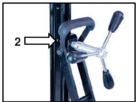
natural_image
Close-up of a bicycle climbing mechanism with labeled component '2' (no text or symbols on the mechanism itself)natural_image
Close-up of a green industrial machine component with a white arrow pointing to a circular component (no text or symbols visible)
natural_image
Close-up of a green industrial machine component with a dial indicator and a white arrow pointing to a circular component labeled 'K' (no readable text or symbols beyond the label)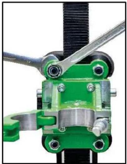
natural_image
Close-up of a green mechanical clamp or bracket assembly with metal fittings and a black threaded rod (no visible text or symbols)natural_image
Close-up of a green mechanical clamp or fixture with a hand adjusting a black tool (no visible text or symbols)natural_image
Green mechanical clamp device with labeled parts (1 and 2), no visible text or symbols beyond labelsDe Boorinstallatie Verankeren
Centreringsindicator boorgat:
natural_image
Close-up of a mechanical component with a metallic cable and a cross mark, no visible text or symbolsnatural_image
Close-up of a green mechanical clamp or bracket component with threaded ends and a labeled part (1), no visible text or symbols.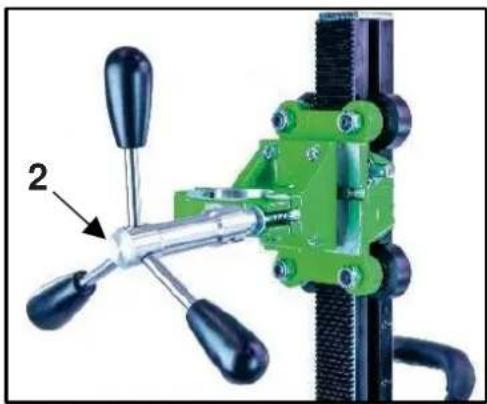
natural_image
Close-up of a green industrial clamping device with three blades and a handle, labeled with number 2 (no text or symbols on the device itself)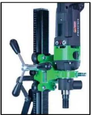
natural_image
Close-up of a green and black industrial machine with drill bit and control lever (no visible text or symbols)
natural_image
Close-up of a mechanical clamp or bracket component with a white arrow pointing to a specific part (no text or symbols visible)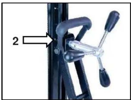
natural_image
Close-up of a mechanical clamp or bracket with a labeled component (no text or symbols visible)natural_image
Close-up of a green industrial machine component with a white arrow pointing to a circular component (no text or symbols visible)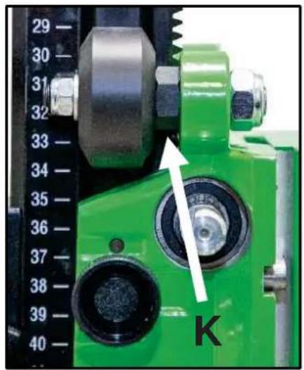
natural_image
Close-up of a green industrial machine component with a dial indicator and a white arrow pointing to a circular component labeled 'K' (no readable text or symbols beyond the label)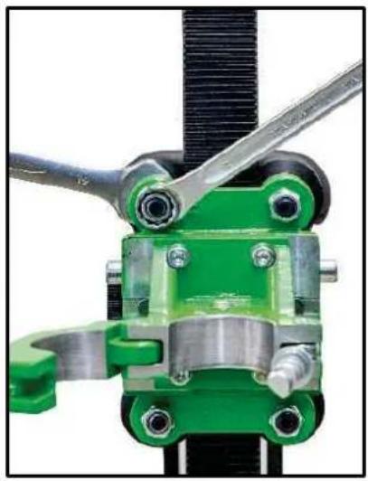
natural_image
Close-up of a mechanical clamp assembly with green and metallic components (no visible text or symbols)Lothar Lässig General Manager
16.05.2024
natural_image
Close-up of a green mechanical clamp or fixture with a hand adjusting a black tool (no visible text or symbols)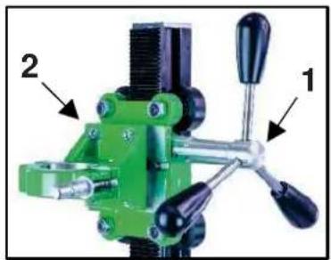
natural_image
Green mechanical clamp device with labeled parts (1 and 2), no visible text or symbols beyond labelsnatural_image
Close-up of a mechanical clamp or bracket with a metallic hook and metal clip, connected by a wire to a cross symbol (no text or labels visible)natural_image
Close-up of a green industrial mechanical clamp or bracket component with threaded ports and a labeled part (1), no visible text or symbols.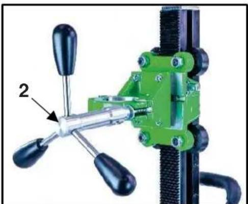
natural_image
Close-up of a green mechanical clamp or fixture with black handles and a labeled component (no text or symbols visible)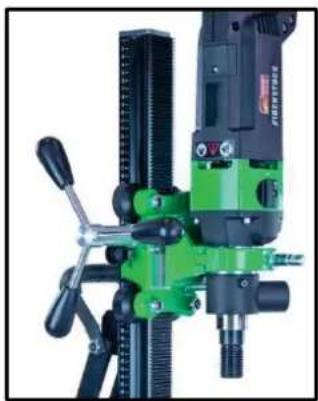
natural_image
Close-up of a green and black industrial machine with no visible text or symbols
natural_image
Close-up of a black mechanical clamp or bracket component with bolts and a numbered annotation (1), no visible text or symbols.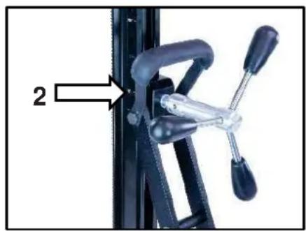
natural_image
Close-up of a bicycle climbing mechanism with black levers and lever (no text or symbols visible)natural_image
Close-up of a green industrial machine component with a white arrow pointing to a circular component (no text or symbols visible)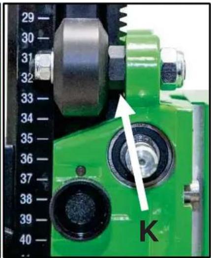

natural_image
Close-up of a green mechanical clamp or bracket assembly with metal fittings and a black rod (no visible text or symbols)

- Nur für EU-Länder
- Important Instructions
- Technical Data
- Supply
- Application for Indented Purpose
- Electrical Connection
- Additional Handle
- Switching ON and OFF
- Short-time operation
- Long-time operation
- Attention!
- Dust Exhaustion
- Engaging and Disengaging of the percussion
- Manual Drilling
- Drill Bits
- Changing Drill Bits
- After Drilling
- Rig Drilling
- Overload Protection
- Safety Clutch
- Care and Maintenance
- Before the beginning of the maintenance- or repair works you have to disconnect plug from the mains.
- Environmental Protection
- Raw material recycling instead of waste disposal
- Only for EU countries
- Noise Emission / Vibration
- Wear ear protectors!
- Dust Protection
- Trouble Shooting
- Auto-stop brushes
- Warranty
- EU - Declaration of Conformity
- GB - Declaration of Conformity
- Solo per i paesi UE
- DANSK
- Kun for EU lande
- EIBENSTOCK
- Vakuum Technik
- Mounting machine holder
- Use
- Mounting the turnstile
- Fastening of the drill rig
- Hole centering indicator:
- Fastening by means of dowels in concrete
- Fastening by means of quick action bracing unit
- Fixing the core drill motor
- Wear protective gloves! Caution! When mounting the machine, risk of squashing!
- Mounting the core drill machine
- For operation with the core drill machine you have to attend the operating instructions and the safety indications!
- Operations
- Details of the work area
- Space requirements for operating and maintenance
- Drilling
- Angled drilling
- Demounting the core drill unit
- Behaviour at malfunction
- FRANÇAIS
- Consignes en cas de panne
- De Boorinstallatie Verankeren
- Centreringsindicator boorgat:
Brand : Eibenstock
Model : DSE 162
Category : Electric drill