
RCMT-352M - Kitchen accessory Royal Catering - Free user manual and instructions
Find the device manual for free RCMT-352M Royal Catering in PDF.

| Product type | Manual meat tenderizer |
| Brand | Royal Catering |
| Model | RCMT-352M |
| Dimensions (W x D x H) | 240 x 320 x 440 mm |
| Weight | 4.5 kg |
| Frame material | Stainless steel and ABS plastic |
| Blade material | Stainless steel |
| Mechanism | Manual crank |
| Max meat capacity | Max thickness 2.5 cm |
| Blade type | Multi-blade set |
| Included accessories | Guidance pliers, Allen key, mounting screws |
| Intended use | Tenderizing meat (domestic use) |
| Assembly | Mounting of feet, hopper, handle required |
| Cleaning | Disassemblable, wash with soapy water, brush blades |
| Maintenance | Food-grade silicone spray recommended after cleaning |
| Safety | Sharp blades, use pliers, do not insert fingers |
| Storage | Dry and cool place, out of reach of children |
| Power source | Manual (no electrical source required) |
| Usage period | Domestic only |
| Manufacturer | Royal Catering |
Frequently Asked Questions - RCMT-352M Royal Catering
User questions about RCMT-352M Royal Catering
0 question about this device. Answer the ones you know or ask your own.
Ask a new question about this device
Download the instructions for your Kitchen accessory in PDF format for free! Find your manual RCMT-352M - Royal Catering and take your electronic device back in hand. On this page are published all the documents necessary for the use of your device. RCMT-352M by Royal Catering.
USER MANUAL RCMT-352M Royal Catering
natural_image
Abstract white line drawing of a stylized creature or mythical creature on a dark blue background (no text or symbols)| DE | Produktname | MANUELLER FLEISCHKLOPFER |
| EN | Product name | MANUAL MEAT TENDERIZER |
| PL | Nazwa produktu | KOTLECIARKA RĘCZNA |
| CZ | Název výrobku | RUČNÍ TENDERIZÉR NA MASO |
| FR | Nom du produit | ATTENDRISSEUR DE VIANDE MANUEL |
| IT | Nome del prodotto | INTENERITRICE PER CARNE MANUALE |
| ES | Nombre del producto | ABLANDADOR DE CARNE MANUAL |
| HU | Termék neve | HÚSKLOPFOLÓ - MANUÁLIS |
| DA | Produktnavn | K∅DHAMMER MED HÅNDSVING |
| FI | Tuotteen nimi | MANUAALINEN PIHVIKONE |
| NL | Productnaam | VLEESVERMALSER HANDLEIDING |
| NO | Produktnavn | MANUELL KJ∅TTM∅RNING |
| SE | Produktnamn | MANUELL KÖTTMÖRARE |
| PT | Nome do produto | PICADOR DE MÃO |
| SK | Názov produktu | RUČNÝ ZMÄKČOVAČ MÄSA |
| DE | Modell | RCMT-352M |
| EN | Product model | |
| PL | Model produktu | |
| CZ | Model výrobku | |
| FR | Modèle | |
| IT | Modello | |
| ES | Modelo | |
| HU | Modell | |
| DA | Model | |
| FI | Tuotteen malli | |
| NL | Productmodel | |
| NO | Produktmodell | |
| SE | Produktmodell | |
| PT | Modelo do produto | |
| SK | Model | |
| DE | Hersteller | expondo Polska sp. z o.o. sp. k. |
| EN | Manufacturer | |
| PL | Producent | |
| CZ | Výrobce | |
| FR | Fabricant | |
| IT | Produttore | |
| ES | Fabricante | |
| HU | Termelő | |
| DA | Producent | |
| FI | Valmistaja | |
| NL | Producent | |
| NO | Produsent | |
| SE | Tillverkare | |
| PT | Fabricante | |
| SK | Výrobca | |
| DE | Anschrift des Herstellers | ul. Nowy Kisielin – Innowacyjna 7, 66-002 Zielona Góra | Poland, EU |
| EN | Manufacturer Address | |
| PL | Adres producenta | |
| CZ | Adresa výrobce | |
| FR | Adresse du fabricant | |
| IT | Indirizzo del produttore | |
| ES | Dirección del fabricante | |
| HU | A gyártó címe | |
| DA | Producentens adresse | |
| FI | Valmistajan osoite | |
| NL | Adres producent | |
| NO | Produsentens adresse | |
| SE | Tillverkarens adress | |
| PT | Endereço do fabricante | |
| SK | Adresa výrobcu |

natural_image
Technical line drawing of a mechanical bracket assembly with mounting holes and bolts (no text or symbols)natural_image
Line drawing of a mechanical component with mounting holes and a tool, no text or symbols presentnatural_image
Technical line drawings of mechanical components including a motor, gear, and base frame (no text or symbols)This User Manual has been translated for your convenience using machine translation. Reasonable efforts have been made to provide an accurate translation; however, no automated translation is perfect nor is it intended to replace human translators. The official User Manual is the English version. Any discrepancies or differences created in the translation are not binding and have no legal effect for compliance or enforcement purposes. If any questions arise related to the accuracy of the information contained in the User Manual, please refer to the English version of those contents which is the official version.
Technical data
| Parameter description | Parameter value |
| Product name | Manual meat tenderizer |
| Model | RCMT-352M |
| Dimensions [width x depth x height; mm] | 240 x 320 x 440 |
| Weight [kg] | 4.5 |
1. General description
The user manual is designed to assist in the safe and trouble-free use of the device. The product is designed and manufactured in accordance with strict technical guidelines, using state-of-the-art technologies and components. Additionally, it is produced in compliance with the most stringent quality standards.
DO NOT USE THE DEVICE UNLESS YOU HAVE THOROUGHLY READ AND UNDERSTOOD THIS USER MANUAL.
To increase the product life of the device and to ensure trouble-free operation, use it in accordance with this user manual and regularly perform maintenance tasks. The technical data and specifications in this user manual are up to date. The manufacturer reserves the right to make changes associated with quality improvement. The device is designed to reduce noise emission risks to a minimum, taking into account technological progress and noise reduction opportunities.
Legend

Read instructions before use.

WARNING! or CAUTION! or REMEMBER!
General warning sign.

ATTENTION! Hand crush hazard!

PLEASE NOTE! Drawings in this manual are for illustration purposes only and in some details may differ from the actual product.
2. Usage safety

ATTENTION! Read all safety warnings and all instructions. Failure to follow the warnings and instructions may result in serious injury or even death.
The terms "device" or "product" are used in the warnings and instructions to refer to: Manual meat tenderizer
2.1. Safety in the workplace
a) Make sure the workplace is clean and well lit. A messy or poorly lit workplace may lead to accidents. Try to think ahead, observe what is going on and use common sense when working with the device.
b) If you are unsure about whether the product is operating correctly or if you find damage, please contact the manufacturer's service centre.
c) Please keep this manual available for future reference. If this device is passed on to a third party, the manual must be passed on with it.
d) Keep packaging elements and small assembly parts in a place not available to children.
e) Keep the device away from children and animals.

Remember! When using the device, protect children and other bystanders.
2.2. Personal safety
a) Do not use the device when tired, ill or under the influence of alcohol, narcotics or medication which can significantly impair the ability to operate the device.
b) The device is not designed to be handled by persons (including children) with limited mental and sensory functions or persons lacking relevant experience and/or knowledge unless they are supervised by a person responsible for their safety or they have received instruction on how to operate the device.
c) When working with the device, use common sense and stay alert. Temporary loss of concentration while using the device may lead to serious injuries.
d) Do not wear loose clothing or jewellery. Keep hair and clothes away from moving parts. Loose clothing, jewellery or long hair may get caught in moving parts.
e) The device is not a toy. Children must be supervised to ensure that they do not play with the device.
f) Do not put your hands or other items inside the device while it is in use!
2.3. Safe device use
a) When not in use, store in a safe place, away from children and people not familiar with the device who have not read the user manual. The device may pose a hazard in the hands of inexperienced users.
b) Clean the device regularly to prevent stubborn grime from accumulating.
c) The device is not a toy. Cleaning and maintenance may not be carried out by children without supervision by an adult person.
d) It is forbidden to interfere with the structure of the device in order to change its parameters or construction.
e) Keep the device away from sources of fire and heat.
f) The device may only be used for meat mincing.
g) Never mince:
- hard food products such as grains, nuts or bones using the device.
- hard fiber food products, such as, for example, ginger.
- frozen food products,
- items not intended for consumption.
h) Never push food products through the feeding duct by fingers or other objects.

ATTENTION! Despite the safe design of the device and its protective features, and despite the use of additional elements protecting the operator, there is still a slight risk of accident or injury when using the device. Stay alert and use common sense when using the device.
3. Use guidelines
The device is designed to tenderise meat.
The product is intended for home use only.
The user is liable for any damage resulting from unintended use of the device.
3.1. Preparing for use
APPLIANCE LOCATION
The temperature of environment must not be higher than 40^ C and the relative humidity should be less than 85%. Ensure good ventilation in the room in which the device is being used. There should be at least 10 cm distance between each side of the device and the wall or other objects. The device should always be used when positioned on an even, stable, clean, fireproof and dry surface, and be out of the reach of children and persons with limited mental and sensory functions.
Disassemble the device and all its components and clean them before the first use.
3.2. Assembling the device
A. Connect the left and right legs to the base using the allen key provided and the four base screws and lock washers. Using an allen key and four leg screws and lock washers, attach the left and right legs to the lower housing:
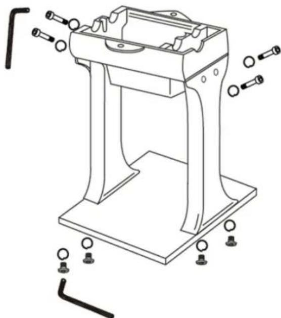
natural_image
Technical line drawing of a mechanical bracket assembly with mounting holes and bolts (no text or symbols)B. Fit the chute to the upper housing using an allen key and two chute screws and lock washers:
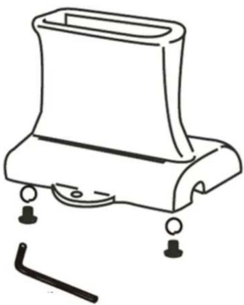
natural_image
Line drawing of a mechanical component with mounting holes and a tool, no text or symbols presentC. Insert the blade assembly into the lower housing, guiding the drive shaft into the bearing journals. Ensure that the gears and blades of the blade assembly are properly meshed and resting in the pivots:
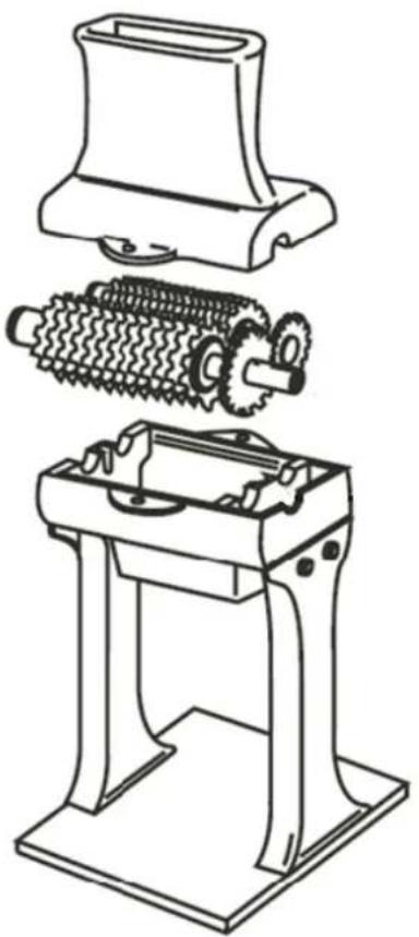
natural_image
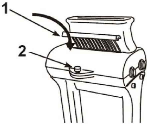
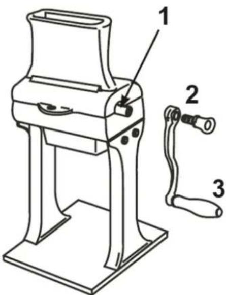
Technical line drawing of a mechanical assembly with three views: top view, side view, and bottom view (no text or symbols)D. Place the upper housing on the lower housing and align the screw holes. Fasten the upper housing to the lower housing using the two housing thumb screws. DO NOT OVERTIGHTEN! Insert combs into the upper housing:
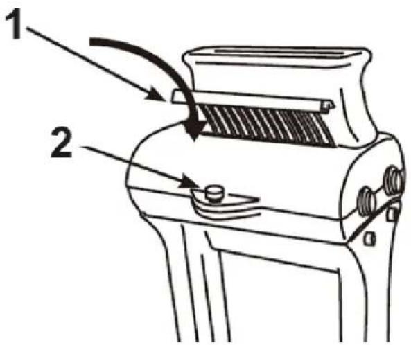
1 - Combs
2 – Housing thumb screws
E. Fit the handle onto the blade drive shaft. Attach the handle to the drive shaft using the handle thumb screw.
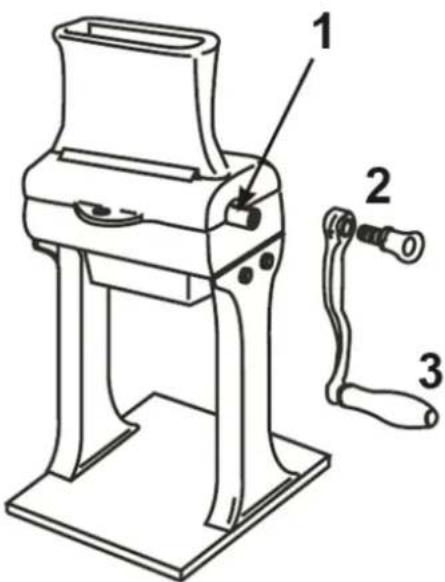
1 – Drive shaft 2 – Handle thumb screw 3 - Handle
3.3. Device use
Remove all bones or hard items from the meat before tenderising. Pushing through bones or hard items may damage the machine.
Do not tenderise meat thicker than 2.5 cm (1"). Thicker meat may get stuck in the blades and damage the product.
Insert the meat into the trough until it comes into contact with the blades. Turn the handle clockwise. This will cause the meat to be pulled through the blades. Only insert one piece of meat at a time to prevent jamming.
If the piece of meat is too short to reach the blades, use the tongs provided to guide the meat to the blades.
CAUTION! DO NOT press or push meat into the chute with your fingers or other objects. This may cause injury and/or damage to the appliance. DO NOT push tongs or other utensils into the blades.
It may be necessary to run the meat through the chopper several times to achieve the desired results. You can also run the meat through at different angles if a different result is desired.
The appliance should be cleaned before and after each use.
NEVER REACH INSIDE THE UNIT. This can cause serious injury. ALWAYS USE THE TONGS PROVIDED.
KEEP YOUR FINGERS AWAY FROM THE BLADES AT ALL TIMES. Failure to do so may result in injury. The blades/blade assembly are very sharp.
DO NOT push or push meat into the chute with your fingers or any other objects. This may cause injury and/or damage to the appliance.
NEVER use your fingers to scrape food from the appliance while it is running. THIS CAN CAUSE SERIOUS INJURY.
DO NOT push the tongs or other utensils into the blades.
3.4. Cleaning and maintenance
1) Remove the handle from the blade stand shaft by unscrewing the handle thumb screw.
2) Lift the combs to remove them from the upper housing.
3) Remove the two thumb screws from the upper housing.
4) Remove the upper housing. WARNING! This will expose the cutting blades. Use caution when handling the blade assembly. Always wear cut resistant gloves (sold separately) when handling the blades.
5) Using the allen spanner provided, remove the chute from the top housing.
6) Carefully lift the blade rack assembly from the lower housing.
7) Remove the lower housing from the legs.
8) Remove the legs from the base.
9) Thoroughly wash all parts with warm soapy water. NOTE: A long bristle brush is recommended for cleaning the blade stand assembly.
10) Rinse with clean water.
11) Disinfect if necessary.
12) Dry thoroughly before reassembly.
NOTE: We recommend coating all metal parts with food grade silicone spray (sold separately) to prevent corrosion.
Use only mild, food-safe detergents to wash the device.
After cleaning the device, all parts should be dried completely before using it again.
Store the unit in a dry, cool place, free from moisture and direct exposure to sunlight.
The device must be regularly inspected to check its technical efficiency and spot any damage.
Use a soft, damp cloth for cleaning.
Do not use sharp and/or metal objects for cleaning (e.g. a wire brush or a metal spatula) because they may damage the surface material of the appliance.
Do not clean the device with an acidic substance, agents of medical purposes, thinners, fuel, oils or other chemical substances because it may damage the device.

natural_image
Technical line drawing of a mechanical bracket assembly with mounting holes and bolts (no text or symbols)natural_image
Line drawing of a mechanical component with mounting holes and a tool, no text or symbols presentnatural_image
Technical line drawing of three mechanical components: a housing, gear mechanism, and a base frame (no text or symbols)natural_image
Technical line drawing of a mechanical bracket assembly with mounting holes and bolts (no text or symbols)natural_image
Line drawing of a mechanical component with mounting holes and a tool, no text or symbols presentnatural_image
Technical line drawing of a mechanical device with three views: top view, side view showing internal gears, and bottom view with base (no text or symbols)natural_image
Technical line drawing of a mechanical bracket assembly with mounting holes and bolts (no text or symbols)natural_image
Line drawing of a mechanical component with mounting holes and a tool, no text or symbols presentnatural_image
Technical line drawing of a mechanical device with three views: top view, side view showing gear and rotor assembly, bottom view with base plate (no text or symbols)natural_image
Technical line drawing of a mechanical bracket assembly with mounting holes and bolts (no text or symbols)natural_image
Line drawing of a mechanical component with mounting holes and a tool, no text or symbols presentnatural_image
Technical line drawings of three mechanical components: a flat housing, a coiled spring, and a base platform (no text or symbols)natural_image
Technical line drawing of a mechanical bracket assembly with mounting holes and bolts (no text or symbols)natural_image
Line drawing of a mechanical component with mounting holes and a tool, no text or symbols presentnatural_image
Technical line drawings of three mechanical components: a flat housing, a coiled spring, and a base platform (no text or symbols)1 - Peines
2 – Tornillos de mariposa de la carcasa
natural_image
Technical line drawing of a mechanical bracket assembly with mounting holes and bolts (no text or symbols)natural_image
Line drawing of a mechanical component with mounting holes and a tool, no text or symbols presentnatural_image
Technical line drawings of mechanical components including a housing, gear mechanism, and base frame (no text or labels)APPARATETS PLACERING
natural_image
Technical line drawing of a mechanical bracket assembly with mounting holes and bolts (no text or symbols)natural_image
Line drawing of a mechanical component with mounting holes and a tool, no text or symbols presentnatural_image
Technical line drawings of three mechanical components: a flat housing, a coiled spring, and a base frame (no text or symbols)D. Placer det øverste hus på det nederste hus, og ret skruehullerne ind. Fastgør det øverste hus til det nederste hus med de to husskruer. MÅ IKKE OVERSPÆNDES! Sæt kammene ind i det øverste hus:
natural_image
Technical line drawing of a mechanical bracket assembly with mounting holes and bolts (no text or symbols)natural_image
Line drawing of a mechanical component with mounting holes and a tool, no text or symbols presentnatural_image
Technical line drawings of mechanical components including a motor, gear, and base frame (no text or symbols)1 – kammat 2 – Kotelon sormiruuvit
1 - Vetoakseli 2 - Kahvan sormiruuvi 3 - Kahva
WAARSCHUWING! of LET OP! of ONTHOUD!
PLAATS VAN HET APPARAAT
natural_image
Technical line drawing of a mechanical bracket assembly with mounting holes and bolts (no text or symbols)natural_image
Line drawing of a mechanical component with mounting holes and a tool, no text or symbols presentnatural_image
Technical line drawings of mechanical components including a motor, gear, and base frame (no text or symbols)natural_image
Technical line drawing of a mechanical bracket assembly with mounting holes and bolts (no text or symbols)natural_image
Line drawing of a mechanical component with mounting holes and a tool, no text or symbols presentnatural_image
Technical line drawing of three mechanical components: a flat plate, a coiled spring, and a base frame (no text or symbols)D. Plasser det øvre huset på det nedre huset og juster skruehullene. Fest det øvre huset til det nedre huset med de to hus tommelskruer. IKKE OVERSTRAM! Sett kammer inn i det øvre huset:

1 - Kam
2 – Tommelskruer på huset
1 - Drivaksel
2 – Håndtak med tommelskrue
3 - Håndtak
APPARATENS PLACERING
natural_image
Technical line drawing of a mechanical bracket assembly with mounting holes and bolts (no text or symbols)natural_image
Line drawing of a mechanical component with mounting holes and a tool, no text or symbols presentnatural_image
Technical line drawings of three mechanical components: a housing, gear mechanism, and a base frame (no text or symbols)1 – Kammar 2 – Husets tumskruvar
natural_image
Technical line drawing of a mechanical bracket assembly with mounting holes and bolts (no text or symbols)natural_image
Line drawing of a mechanical component with mounting holes and a tool, no text or symbols presentnatural_image
Technical line drawings of mechanical components including a housing, gear mechanism, and base frame (no text or symbols)natural_image
Technical line drawing of a mechanical bracket assembly with mounting holes and bolts (no text or symbols)natural_image
Line drawing of a mechanical component with mounting holes and a tool, no text or symbols presentnatural_image
Technical line drawings of three mechanical components: a housing, gear mechanism, and a base frame (no text or symbols)1 – Hrebene 2 – Krídlové skrutky puzdra
E. Nasad'te rukovát na hnací hriadel'čepele. Pripevnite rukovát k hnaciemu hriadel'u pomocou krídlovej skrutky rukováte.
For the disposal of the device please consider and act according to the national and local rules and regulations.
CONTACT
expondo Polska sp. z o.o. sp. k.
- General description
- DO NOT USE THE DEVICE UNLESS YOU HAVE THOROUGHLY READ AND UNDERSTOOD THIS USER MANUAL.
- Legend
- Usage safety
- Safety in the workplace
- Personal safety
- Safe device use
- Use guidelines
- Preparing for use
- Assembling the device
- Device use
- Cleaning and maintenance
- APPARATETS PLACERING
- PLAATS VAN HET APPARAAT
- APPARATENS PLACERING
- CONTACT
Brand : Royal Catering
Model : RCMT-352M
Category : Kitchen accessory