
YT-44085 - Milling template Yato - Free user manual and instructions
Find the device manual for free YT-44085 Yato in PDF.

User questions about YT-44085 Yato
0 question about this device. Answer the ones you know or ask your own.
Ask a new question about this device
Download the instructions for your Milling template in PDF format for free! Find your manual YT-44085 - Yato and take your electronic device back in hand. On this page are published all the documents necessary for the use of your device. YT-44085 by Yato.
USER MANUAL YT-44085 Yato
natural_image
Mechanical switch device with metal components and a YATO brand logo (no visible text or symbols on main body)PL EN DE RU UA LT LV CZ SK HU RO ES FR IT NL GR
natural_image
Diagram of a circular mechanical component with internal features and directional arrows, no text or symbols present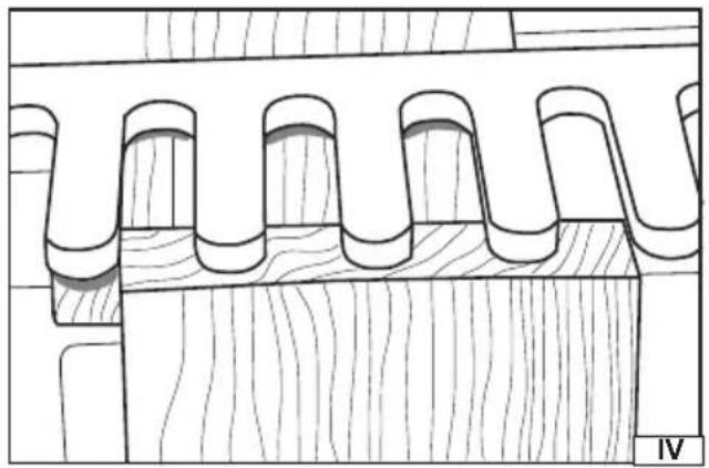
natural_image
Technical line drawing of a wooden architectural element with curved and rectangular features (no text or symbols)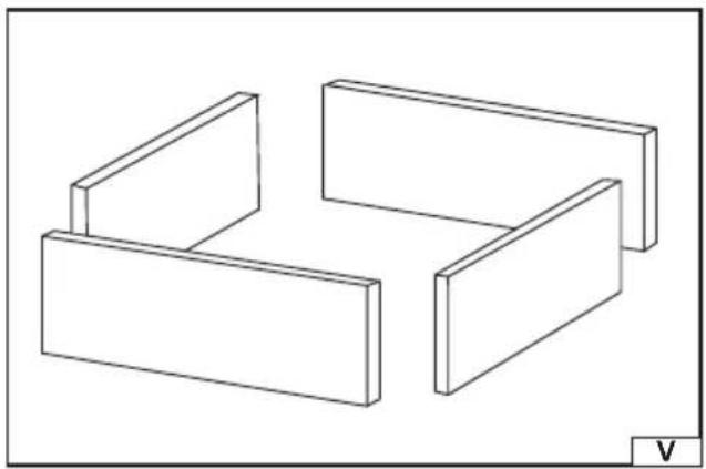
natural_image
Isometric line drawing of three rectangular blocks arranged in a staggered layout (no text or symbols)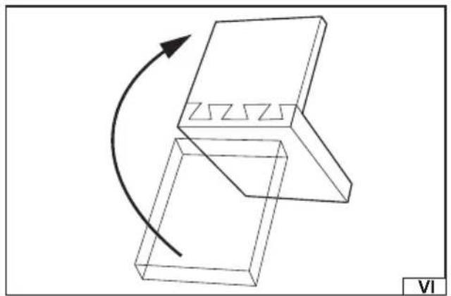
natural_image
Diagram of a mechanical component with a curved arrow indicating rotation or movement, no text or symbols present.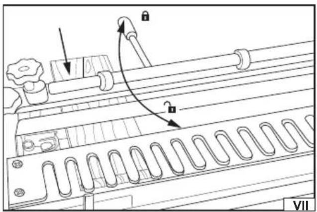
natural_image
Technical line drawing of a mechanical component with no visible text or symbolsnatural_image
Technical line drawing of a mechanical assembly with no visible text or symbols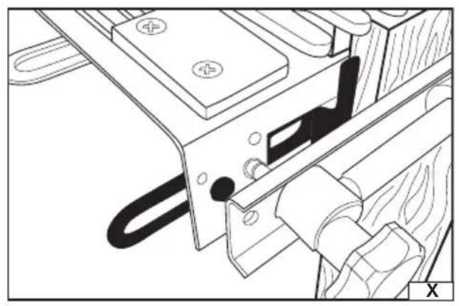
natural_image
Technical line drawing of a mechanical assembly with no visible text or symbols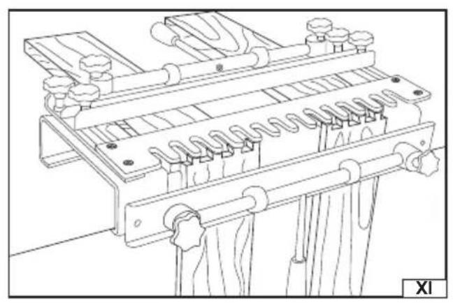
natural_image
Technical line drawing of a mechanical assembly with spring-loaded components and mounting brackets (no text or symbols)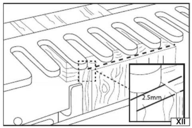
natural_image
Pure mechanical diagram showing gear and cam mechanism without any text or symbols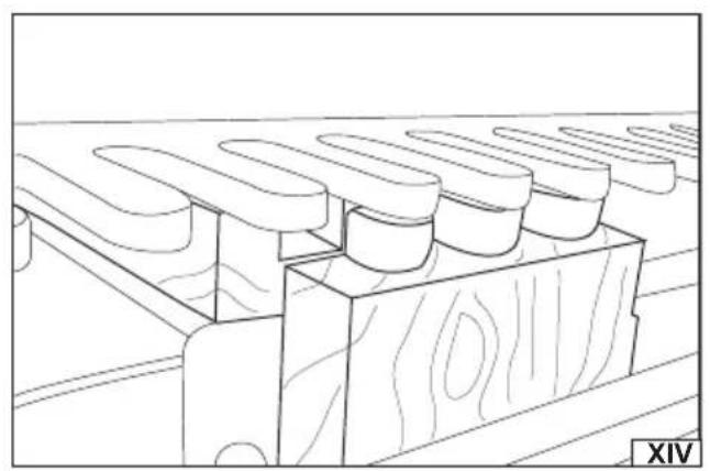
natural_image
Line drawing of a wooden plank with multiple oval cutouts, no text or symbols presentPL
The tool facilitates the preparation of wood elements joints i.e. dovetail joints. The joint is used when making cabinets, boxes, drawers, frames, etc. The tool allows for making joint cuts in both elements to be joined at the same time.
Technical data
Template: 12.7 mm (1/2")
Bushing (available separately): 11.1 mm (7/16")
Bit (available separately): 6.35 mm (1/4") shank – 12.7 mm (1/2) x 14° dovetail
Maximum material thickness: 32 mm
Horizontal width range: 140 – 300 mm
Vertical width range: 150 – 275 mm
Weight: 9.5 kg
PREPARING FOR OPERATION
Warning! Due to sharp edges, it is recommended to unpack the tool while wearing protective gloves. Unpack the tool and dispose of all packaging elements. Check all tool elements for damage during transport.
Installing the tool
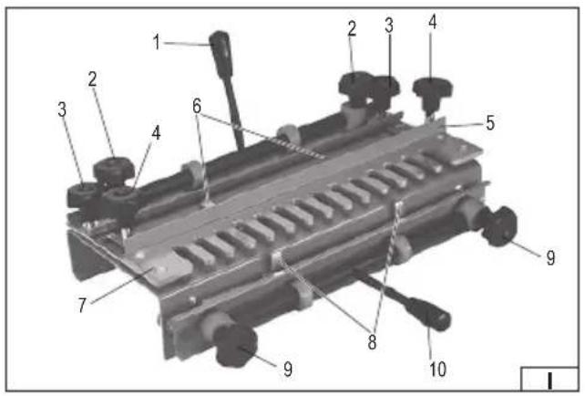
Assemble the tool before starting work. The assembly consists in screwing the horizontal and vertical clamp levers to the tool (I). Tighten the levers firmly and securely. Check that the levers have not come loose before starting any work. Levers can be screwed from both sides of the clamp – make sure that when turning the levers they are away from the templates
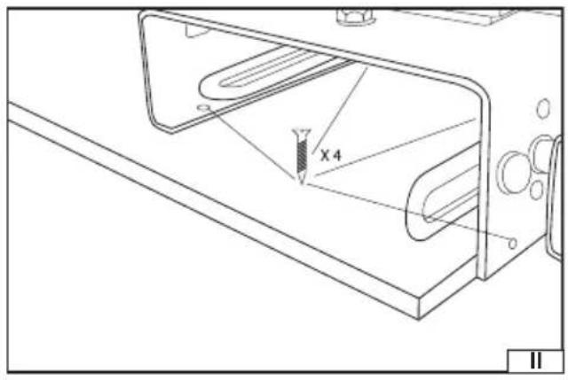
Secure the tool to the work table with four screws (II). Instead of mounting the tool directly to the table, you can attach it to a plate and then fix the plate to the table using clamping elements. The plate should be large enough so that the clamping elements do not interfere with the work.
TOOL OPERATION
Warning! When working with the bit make sure that it will not have contact with any element of the tool. Use a suitable guide bushing. Contact of the bit with the tool may lead to the bit or tool damage. It can also cause serious injury.
Preparing the router
Warning! Carefully read the manual supplied with the router before starting work with the router. The below description relates only to the manner of using the router with the tool and does not present all hazards and methods for avoiding them when operating the router.
The dovetail jig is designed for the interoperation with the following bits: 6.35 mm / 1/4" and 12.7 mm / 1/2".
It may be necessary to use additional accessories to fit the 6.35 mm / 1/4" bit to the router.
Attach a base, which will allow for installing the guide bushing, to the router. Then assemble the guide bushing with a diameter of 11.1 – 12 mm / 7/16". The bushing should move freely between the template slots. The height of the guide bushing should not be greater than the template thickness. Install a dovetail bit 12.7 mm / 1/2" 14° with the 6,35 mm / 1/4" shank.
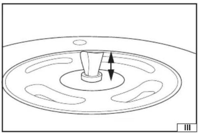
The bit height should be set so that the cutting edge will not have contact with the template. The height of the bit beyond the router should be approx. 17 mm (III).
Material preparation
The material intended for the dovetail joint should be initially prepared by cutting to appropriate dimensions. The material edges should be perpendicular. When determining the dimensions take into account the depth of the cut joint.
The tool, thanks to the offset of the elements to be joined (IV) in relation to each other, allows for making the joint cuts in both elements to be joined at the same time.
It is advisable to pre-assemble the material to be joined (V) and then mark the edges which will be joined together. This will facilitate making correct cuts.
When pre-fitting the elements, make sure that they adhere to each other at the right angles.
Setting the vertical and horizontal stops
Caution! Setting the stops requires the use of a spanner (available separately).
Caution! The elements to be joined should be placed in the template with the inside joining side facing out. After making the joint cuts, the element placed vertically in the template should fit the element placed horizontally at an angle of 180^ in relation to the cut – as if a hinge had been formed at the point of cutting (VI).
Turn the horizontal clamp lever to the back of the tool. Loosen the horizontal clamp knobs and insert the element to be joined from the back of the tool (VII). The material to be joined should be under the backstop and template. The face of the material to
EN
be joined should be flush with the front of the tool housing. This will allow for placing a vertical element to be joined in front of it.
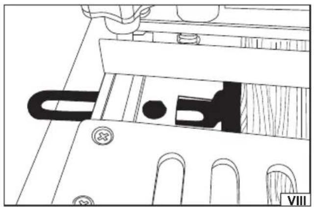
Use the left horizontal stop to position the element to be joined in the desired position to make the joint (VIII).
Tighten the horizontal clamp knobs so that the clamp is close to the element to be joined but does not restrict its movement.
Check the position of the element to be joined, then turn the horizontal clamp lever towards the front of the tool to immobilise the element to be joined.
Caution! The clamp should be set so that the turning of the clamp lever allows the element to be joined to be inserted and fixed without the additional use of the clamping knobs.
Caution! Do not apply excessive force when turning the lever. If there is too much resistance when turning the lever, withdraw the lever and adjust the clamp knobs so that the turning of the lever locks the element without excessive force. This will protect the clamping mechanism from damage.
Turn the vertical clamp lever towards the bottom of the tool. Loosen the vertical clamp knobs.
Insert the vertical element to be joined. The material to be joined should be under the backstop and have contact with the vertical edge of the frame (IX). As with the horizontal element, adjust the knobs so that the element to be joined can be fixed by turning the lever.
Adjust the left vertical stop to 12.7 mm / 1/2" relative to the right side of the horizontal stop (X). This is an offset corresponding to the width of the template element (tine).
Set the left side of the element to be joined on the left side of the vertical stop.
Position the vertical element so that its top edge is flush with the top surface of the horizontal element (IV).
Turn the vertical clamp lever to immobilise the vertical element in the tool.
Caution! Use the right horizontal and vertical stops to secure and align the larger elements to be joined more centrally in the template.
Simultaneous cutting of two joints
Use the stops on the right with the second pair of elements to be joined to allow two dovetail joints to be made at the same time (XI).
The use of left or right clamping knobs allows the elements to be joined and set on one side without affecting the setting on the other side. In this case, the knob is used instead of the clamp levers.
Once the stops are in the correct position, align the elements to be joined at the same level and avoid readjustment of the stops.
This is only possible if the elements to be joined are of the same size.
Instead, once the correct offset between the vertical and horizontal stops is set, the spacer can be cut from a small piece of wood.
This will enable the offset position to be set quickly and accurately, even with different sizes of the elements to be joined.
Template position adjustment
To adjust the template position unscrew the template position knobs and adjust the template position to the thickness of the element to be joined making sure that the template is aligned on both sides. The template's face should be approximately 2.5 mm from the front edge of the vertical element (XII).
Backstop adjustment
The backstop controls the depth of the female cuts, limiting the movement of the router base.
There are no fixed distance values because the distance depends on the size of the router base and the thickness of the elements to be joined.
The distance should be determined according to the following formula:
Distance = (2 x thickness of the vertical element to be joined) + (1/2 x router base width) - (bit radius)
This is the measurement from the backstop to the end of the template cuts (tines). When using the recommended 12.7 mm / 1/2" dovetail bit, the cutting radius will be 6.35 mm (1/4").
Caution! When using a router without a fully round base (a router with 2 flat sides of the base), measure the distance from the centre of the base to the end of the edge closer to the centre of the base. When working with the router, remember to work to the side of the base that has been measured. If the widest base distance is set, there is a risk of the bit coming into contact with the template. In this case, use the side of the base closer to the bit.
Cutting the dovetail joints
Ensure that the router and the tool are correctly set according to the above recommendations. It is advisable to make a trial cut on the waste material, especially if it is the first cut with the tool.
Use protective clothing including: a dust mask if there is a risk of inhaling toxic particles, for example when working with wooden composite material.
Set the router speed so that it is not faster than the speed of the bit used.
Place the router over the template with the bit in such a position that it does not touch the material to be cut, but is in the ideal
EN
position to start cutting.
Holding the router securely, start it and wait until the bit reaches full speed.
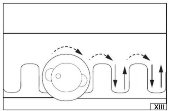
Carefully start cutting, allowing the guide bushing to follow the slot pattern on the template (XIII). The result of the cut should look like in figure XIV.
Caution! Do not cut slots individually, but instead make the cut in one process, carefully following the shape of the template.
Warning! When cutting, make sure that the bit does not come into contact with any part of the template. The bit should also not be lifted before the cut is completed.
Once the cut is complete, turn off the router and wait for the bit to completely stop and remove it from the template.
After finishing the cut, slide the elements to be joined out of the template and check the joint made.
Caution! The correct joint should be neither too loose nor too tight. If the joints made are incorrect, or if you need to gain more experience in making dovetail joints, cut off the joint made with a saw and try again.
If the joint is too tight, it may be helpful to strike it using low force with a wooden or rubber mallet to bring the pieces together.
MAINTENANCE
After finishing work clean the tool of the dust using a jet of compressed air with a pressure of not more than 0.3 MPa by using for example industrial vacuum cleaner or soft brush. If the tool is soiled with resin, clean it with a resin remover. Store the tool in a well-ventilated place protecting it from moisture and direct sunlight.