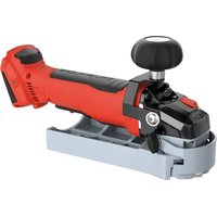
PF 80-18 PURE - Plane Mafell - Free user manual and instructions
Find the device manual for free PF 80-18 PURE Mafell in PDF.


| Product Type | Cordless Surface Planer |
| Brand | Mafell |
| Model | PF 80-18 PURE |
| Service Voltage | 18 V DC |
| Motor Type | Brushless |
| No-Load Speed | 10,000 min⁻¹ |
| Cutter Diameter | 80 mm |
| Suction Connector Diameter | 35 mm |
| Weight (without battery) | 2.8 kg |
| Dimensions (L x W x H) | 316 x 160 x 162 mm |
| Max. Surfacing Capacity | 10 mm |
| Battery Type | CAS Li-ion (Cordless Alliance System) |
| Main Functions | Surfacing, flush trimming |
| Safety | Rotatable protective ring, spindle lock, automatic brake, restart protection, safety switch |
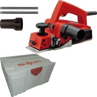
| Standard Equipment | Milling head with 4 reversible blades, suction connector, 2 service tools, transport case, instruction manual, safety booklet |
| Maintenance and Cleaning | Regular cleaning of ventilation slots, resin removal from cutters (soak for 24h in petroleum or anti-resin product) |
| Spare Parts and Repairability | Reversible blades (ref. 034907), battery packs (ref. 094500 onwards), authorized Mafell after-sales service |
| Sound Level | Sound pressure L_PA = 90 dB(A), sound power L_WA = 98 dB(A) (K=3 dB) |
| Hand-Arm Vibration | < 3.3 m/s² |
| Intended Use | Surfacing and flush trimming of excess material on solid wood or wood-based materials |
| Storage and Transport | Store in a dry place, transport Li-Ion batteries according to dangerous goods regulations |
Frequently Asked Questions - PF 80-18 PURE Mafell
User questions about PF 80-18 PURE Mafell
0 question about this device. Answer the ones you know or ask your own.
Ask a new question about this device
Download the instructions for your Plane in PDF format for free! Find your manual PF 80-18 PURE - Mafell and take your electronic device back in hand. On this page are published all the documents necessary for the use of your device. PF 80-18 PURE by Mafell.
USER MANUAL PF 80-18 PURE Mafell
natural_image
3D rendered mechanical device with a cylindrical component and control knob, mounted on a base (no visible text or symbols)MAF02404/a
WARNUNG
Please read all safety instructions and directions. Failure to comply with the safety instructions and directions can cause electric shock, fire and/or serious injuries. Please retain all safety instructions and directions for future reference.
AVERTISSEMENT
GB · EC Declaration of Conformity
We herewith confirm that the machine PF 80-18 complies with the EU directives quoted. The standards listed were used for design and construction. Empowered person for the configuration of the technical documents: Mafell AG
natural_image
Technical illustration of a mechanical component with directional arrows indicating motion or assembly (no text or symbols)Abb. 3
natural_image
3D mechanical component diagram with dimension label '6' and directional arrow (no readable text or symbols)MAF02399/a
Abb. 5
Abb. 7
| 1 | Signs and symbols | 18 |
| 2 | Product information | 18 |
| 2.1 | Manufacturer's data | 18 |
| 2.2 | Information on the rechargeable battery | 18 |
| 2.3 | Machine identification | 18 |
| 2.4 | Technical data | 19 |
| 2.5 | Emissions | 19 |
| 2.6 | Scope of supply | 19 |
| 2.7 | Intended use | 20 |
| 2.8 | Residual risks | 20 |
| 3 | Safety instructions | 20 |
| 4 | Layout | 21 |
| 4.1 | Depicted components | 21 |
| 5 | Setting / adjustment | 22 |
| 5.1 | Charging the rechargeable battery | 22 |
| 5.2 | Rotatable rechargeable battery | 22 |
| 5.3 | Battery charge level and signal display | 22 |
| 5.4 | Fitting the rechargeable battery | 22 |
| 5.5 | Removing the rechargeable battery | 23 |
| 5.6 | Chip extraction | 23 |
| 5.7 | Changing the cutter | 23 |
| 5.8 | Changing the indexable cutting insert | 23 |
| 6 | Operation | 24 |
| 6.1 | General | 24 |
| 6.2 | Switching on and off | 24 |
| 6.3 | Work instructions | 24 |
| 6.4 | Flush milling | 24 |
| 7 | Service and maintenance | 25 |
| 7.1 | Machine | 25 |
| 7.2 | Cutter | 25 |
| 7.3 | Storage | 25 |
| 7.4 | Transport | 25 |
| 7.5 | Disposal of rechargeable batteries/batteries | 25 |
| 8 | Troubleshooting | 26 |
| 9 | Optional accessories | 27 |
| 10 | Exploded drawing and spare parts list | 27 |
1 Signs and symbols

This symbol is found in all places where you will find information for your safety.
Non-compliance with these instructions may result in very serious injuries.

This symbol indicates a potentially hazardous situation.
If this situation is not avoided, the product or objects in its vicinity may get damaged.

This symbol indicates tips for the user and other useful information.
2 Product information
for machine with Art.-No. 91F102
2.1 Manufacturer's data
MAFELL AG, Beffendorfer Straße 4, D-78727 Oberndorf / Neckar, Phone +49 (0)7423/812-0, Fax +49 (0)7423/812-218, e-mail: mafell@mafell.de
2.2 Information on the rechargeable battery
The CE Declaration of Conformity with regard to the rechargeable batteries can be found on our website www.mafell.com in the footer area under the header Legal Matters, Declaration of Conformity.
2.3 Machine identification

CE symbol to document compliance with the basic safety and health requirements according to Appendix I of the Machinery Directive.
For EU countries only
Do not dispose of electrical tools together with domestic waste!
In accordance with the European directive 2002/96/EC on waste electrical and electronic equipment and transposition into national law, obsolete electrical tools must be collected separately and recycled in an environmentally-compatible manner.

Read the operating instructions. This reduces the risk of injury.

Protect the rechargeable battery from heat, excessive solar radiation, fire, frost, water and humidity.
Protect rechargeable battery packs from humidity!

Protect rechargeable battery packs from fire!
There is danger of explosion!

Cordless Alliance System (=CAS) is a cross-manufacturer battery pack system.
Further information is available at www.cordless-alliance-system.com
2.4 Technical data
| Type of motor | brushless |
| Operating voltage | 18 V DC |
| Speed during idling | 10000 min ^-1 |
| Hose connector diameter | 35 mm (1.37 inches) |
| Cutter diameter | 80 mm (3.15 inches) |
| Weight without rechargeable battery | 2.8 kg (6.17 lbs) |
| Dimensions (W x L x H) | 160 x 316 x 162 mm (6.30 x 12.44 x 6.38 inches) |
2.5 Emissions
The declared noise emission values have been measured in accordance with EN 62841-1 and may be used for comparing the tool with another and also in a preliminary assessment of exposure.

Danger
The noise emissions during actual use of the power tool can differ from the declared values depending on the ways in which the tool is used especially what kind of workpiece is processed.
Always wear hearing protection, even when the power tool is running idle in addition to the trigger time!
2.5.1 Noise emission specifications
Noise emission values determined according to EN 62841:
| Sound pressure level | L_PA = 90 dB (A) |
| Uncertainty | K_PA = 3 dB (A) |
| Sound power level | L_WA = 98 dB (A) |
| Uncertainty | K_WA = 3 dB (A) |
The noise measurement was done without tool at idling speed.
2.5.2 Vibration specifications
The typical hand-arm vibration is less than 3.3 m/s ^2 .
2.6 Scope of supply
Face-milling cutter PF 80-18 complete with:
1 milling head
1 hose connector
2 operating tools
1 carrying case
1 operating manual
1 folder "Safety instructions"
2.7 Intended use
The face-milling cutter PF 80-18 is suitable for face and flush milling of material projections over flat surfaces made of solid wood or wood-like materials.
For this, the base plate of the machine must rest on the flat areas of the workpiece. Hand-guided processing is not permitted. (Risk of backlash)
Only use the tool included in the delivery.
Do not remove any safety devices to enable work other than that described above.
Any other use than described above is not permissible. The manufacturer cannot be held liable for any damage arising from such other use.
So as to use the machine as intended, comply with the operating, maintenance and repair instructions specified by Mafell.
Only use original Mafell / CAS rechargeable batteries and accessories.
2.8 Residual risks

Danger
Even if used in accordance with its intended purpose and despite conforming with the safety instructions, residual risks caused by the intended use that can lead to health consequences will always remain.
- Machine backlash.
- Touching the milling cutter below the protective ring.
- Touching the milling cutter when the protective ring is open.
- Putting down the machine while the tool is coasting to a standstill and a resulting unexpected movement of the machine or of an entrained object.
- Breakage and hurling out of the tool or parts of the tool.
- Hearing can be impaired when working for long periods without ear protectors.
- Emission of harmful wood dusts during longer operation without extraction.
3 Safety instructions

Danger
Always observe the following safety instructions and the safety regulations applicable in the respective country of use! Please also read the safety information in the enclosed folder 070500 "Safety instructions" (according to standard 62841-1).
General instructions:
- Only hold the power tool by the insulated gripping surfaces when carrying out work during which the bit may hit concealed power lines. Cutting accessory contacting a "live" wire may make exposed metal parts of the power tool "live" and could give the operator an electric shock.
- Use clamps or another practical way to secure and support the workpiece to a stable platform. Holding the workpiece by your hand or against the body leaves it unstable and may lead to loss of control.
- Never work without the protection devices stipulated for the respective operating sequence and do not effect any modifications on the machine that could impair safety.
- Please note the instructions in Chapter 6.4 regarding flush milling.
- Children and adolescents must not operate this machine. This rule does not apply to young persons receiving training and being supervised by an expert.
- Do not put down the machine before the tool has coasted to a standstill.
- Protect the machine and the rechargeable batteries from humidity!
- Do not throw the rechargeable batteries into a fire!
- Do not use any defective or deformed rechargeable batteries!
- Do not open the rechargeable batteries!
-
Do not touch the contacts of the rechargeable batteries and do not short-circuit them!
-
A slightly acidic, combustible liquid may leak from defective li-ion rechargeable batteries! If any battery liquid is leaking and comes in contact with the skin, immediately rinse with a copious amount of water. If any battery liquid gets into your eyes, rinse with clean water and immediately consult a doctor for medical treatment!
- Remove the rechargeable batteries from the machine before carrying out any setting, retooling, maintenance or cleaning tasks.
- Ensure that the machine is switched off when you push in the rechargeable battery.
- Please remove the rechargeable battery from the machine if the machine is put down, transported or stored unattended.
Instructions on the use of personal protective equipment:
- Always wear ear protectors during work.
- Always wear protective goggles during work.
- Always where a dust mark during work.
Instructions on operation:
- Keep your hands away from the cutting range and the tool. With your other hand, support the supplementary handle or the motor casing.
- Never support the workpiece in your hand or over your leg. Secure the workpiece against a sturdy support, e.g. by means of clamps.
- Never use damaged or incorrect tool washers or screws.
- Hold the machine with both hands and bring your arms into a position where you are able to resist the backlash forces.
- Examine the workpiece for foreign objects. Do not saw or mill into steel parts.
- Always mill in counter direction.
- Before starting up, check the tight seat of the milling cutter and its correct running.
- Only use milling cutters approved for manual feed. Only use the tool included in the delivery or a corresponding spare part.
- Do not reach under the protective ring.
- Only swing the protective ring upwards when flush milling (see Chapter 6.4).
- Remove the battery before changing tools, making adjustments, performing maintenance, or
troubleshooting (this includes removing jammed splinters).
- Before switching on, make sure that the milling cutter is tightly secured.
- Only switch on the machine once its rests on the flat surface to be processed. After processing, switch off the machine and only lift it off the workpiece once the tool has coasted to a standstill.
- Only begin milling the workpiece when the milling cutter has achieved its full speed.
- Examine the workpiece for foreign objects. Do not mill into metal parts, e.g. nails.
- Only start working if the base plate can be securely rested on the workpiece.
- Hand-guided milling is not permitted.
- The wood dust arising during milling impairs the necessary view and is partly injurious to health. If the machine is used for longer periods, it must therefore be connected to a chip extractor if the work is not carried out outdoors or in a sufficiently ventilated room.
Instructions on service and maintenance:
- Regularly cleaning the machine, especially the adjusting devices and guides, constitutes an important safety factor.
- Only original MAFELL spare parts and accessories may be used. Otherwise the manufacturer will not accept any warranty claims and cannot be held liable.
4 Layout
4.1 Depicted components
(see Fig. 1, 2, 4)
(1) Base plate
(2) Protective ring
(3) Spindle lock button
(4) Handle
(5) Grip area
(6) Rechargeable battery
(7) Switch trigger
(8) Cutter head
(9) Indexable cutting inserts
5 Setting / adjustment
5.1 Charging the rechargeable battery
Check whether the rated voltage of the rechargeable battery agrees with the information specified on the machine.
Rechargeable battery and charger are matched to each other. Only use original Mafell / CAS rechargeable batteries and chargers.
Before using a new machine, first of all charge the rechargeable battery.

The charging operation is described in the instructions supplied with the charger.
The rechargeable battery is equipped with a temperature monitoring system. This guarantees that the rechargeable battery is only charged in the temperature range between 0°C and 50°C. This achieves a long service life for the rechargeable battery.
A considerably shortened operating time per charging procedure indicates that the rechargeable battery is spent and needs to be replaced.

Danger
Explosion hazard
Protect the rechargeable battery from heat, fire and moisture.
Do not place the rechargeable battery onto heating appliances and do not expose the rechargeable battery to strong solar radiation for a longer period of time. Temperatures above 50°C are detrimental to the rechargeable battery. Allow a heated rechargeable battery to cool down before charging it.
The optimum storage temperature ranges between 10^ C and 30^ C.

Do not open the rechargeable battery and protect it from impacts. Keep the rechargeable battery in a dry and frost-proof place.

Danger
Cover the rechargeable battery's contacts if it is stored outside the charger. There is a fire and explosion hazard in case of a short circuit caused by metallic bridging.

Follow the instructions for the protection of the environment.
5.2 Rotatable rechargeable battery
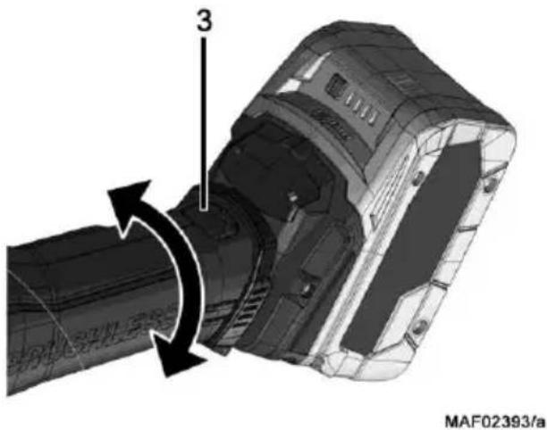
The rear part of the machine can be rotated by 270^ in three stages (see Fig. 3). This allows the machine to be adapted to the working conditions. Only work when the tool is locked in position.
- Press the locking button 3 to start rotating the rear part of the machine.
- Release the locking button 3 during the rotation. Make sure that the locking mechanism engages with an audible click.
natural_image
Technical illustration of a mechanical component with directional arrows indicating motion or rotation (no text or symbols)Fig. 3
5.3 Battery charge level and signal display
Press the button on the battery to query the charge level of the rechargeable battery. The charge level is indicated by LED lights.
If the battery is almost empty, an LED light flashes. Recharge the battery.
5.4 Fitting the rechargeable battery
Before inserting, check whether the rated voltage of the rechargeable battery agrees with the information specified on the machine.

Danger
There is an explosion hazard if the rechargeable battery is replaced incorrectly. Only replace the rechargeable battery with the same or equivalent type.
Inserting: Slide the charged rechargeable battery into the battery guide below the handle until it perceptibly engages.

Before using the machine, convince yourself that the rechargeable batteries are firmly seated in the machine.
5.5 Removing the rechargeable battery
Press the battery release button 14 and pull the battery 6 out of the battery guide (see Fig. 4).
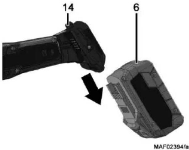
Fig. 4

Do not use force to do so.
5.6 Chip extraction

Danger
Substances that are harmful to health must be taken up with an M-suction device.
Connect the machine to a suitable external dust extractor during all work generating a considerable amount of dust. The air velocity must be at least 20 m/s (65.6 ft / sec.).
The internal diameter of hose connector is 35 mm (1 3/8 in.).
5.7 Changing the cutter

Danger
Unplug the rechargeable battery for all service work.
So as to guarantee its function, the machine is harmonised with the milling cutter included in the delivery, therefore only a corresponding spare part can be used.
- Press and hold the spindle lock button.
- Place the supplied hex nut driver onto the milling head and turn the milling head counterclockwise until it is loosened and can be removed.
- Replace the cutter and tighten it again (13 Nm). Ensure there are no chips on the clamping surfaces.
Deresinification is carried out by soaking the cutters for 24 hours in paraffin or commercially available resin remover.
5.8 Changing the indexable cutting insert

Danger
Unplug the rechargeable battery for all service work.

Danger
Indexable cutting inserts are cutting tools and have sharp corners and sharp edges. Handle these indexable cutting inserts with care to prevent injuries and damage to the inserts.
The milling head is equipped with 4 HM carbide indexable cutting inserts. When the cutting edges become blunt, you can turn the indexable cutting insert up to three times. After that, new original indexable cutting inserts must be fitted!
Follow the procedure below:
- Unscrew the countersunk screws using the supplied SW4 Allen key.
- Clean all parts and the cutter chambers of the milling head.
- Turn or replace the indexable cutting inserts.
- Fasten the indexable cutting inserts with the countersunk screws and tighten them using the SW4 Allen key (4 Nm).
The parts have been inserted correctly if the rear of a cutter edge is resting against the carrier body, and the countersunk screw can be screwed in that far that the surface of the countersunk screw is located below or on the same level as the surface of the indexable cutting insert. The radial blade protrusion of max. 1.1 mm is thus guaranteed.
6 Operation
6.1 General
- Personnel entrusted to work with the machine must be made aware of these operating instructions, calling particular attention to the chapter "Safety instructions".
- Ensure that the cutter is fastened correctly.
6.2 Switching on and off
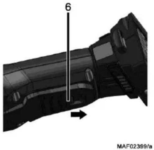
- Switching on: Slide the switch lock in the direction of the arrow and press the switch button 6 (see Fig. 5)
- Switching off: Release switch button 6.
natural_image
3D mechanical component diagram with dimension label '6' and directional arrow, no readable text or symbols beyond the labelFig. 5
As this is a switch without locking device, the machine will only run while this switch button is pressed. The built-in automatic brake limits the working tool's slow-down time to approx. 1-2 s.
The machine is equipped with a restart protection. In case of overload, you must first turn off the machine and then turn it back on.
6.3 Work instructions
- With the protective ring 2 folded down, up to 10 mm high material projections can be milled flat.
- Hold the face milling cutter with both hands at the handle and the motor casing.
- Place the base plate of the machine securely on the flat area of the workpiece.
- Switch on the machine.
- Switch off the machine before removing one of your hands from the machine or before lifting the machine.

Danger
Before putting the machine down, switch off the engine and wait until the working tool has come to a standstill.
6.4 Flush milling
The flush milling function is used to trim excess material flush with a workpiece edge.
Follow the procedure below:
- Loosen the wing screw 10 and swing the protective ring 2 upwards using the gripping surface 11 (Fig. 6).
- Retighten the wing screw to secure the protective ring in the open position.
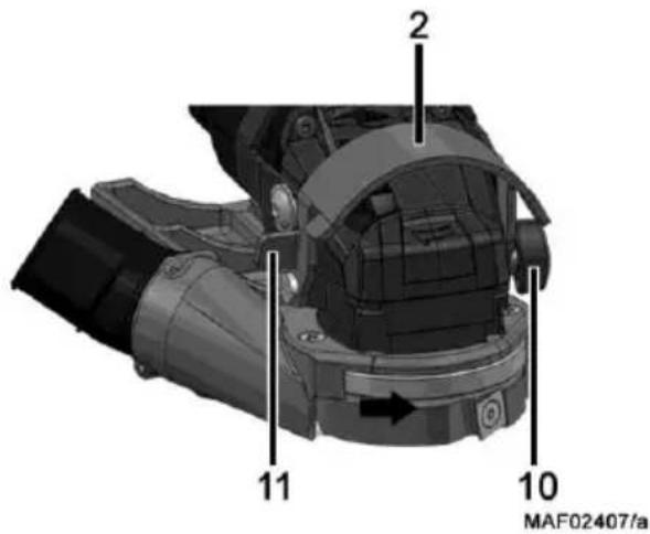
Fig. 6
• After completing the work, return the protective ring 2 to its starting position and secure it with the wing screw 10 (Fig. 7).
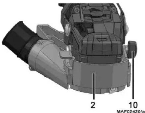
Fig. 7
7 Service and maintenance

Danger
Unplug the rechargeable battery for all service work.
MAFELL machines are designed to be low in maintenance.
The ball bearings used are greased for life. When the machine has been in operation for a longer period of time, we recommend to hand the machine in at an authorised MAFELL customer service shop for inspection.
Only use our special grease, order No. 049040 (1 kg tin) for all greasing points.
7.1 Machine
The machine must be regularly cleaned off deposited dust. The ventilation openings on the motor should be cleaned with a vacuum cleaner.
7.2 Cutter
The cutters used on the machine must be freed from resin regularly as clean tools improve the cutting quality.
For cleaning, only acid-free but not highly alkaline cleaning agents may be used.
Deresinification is carried out by soaking the cutters for 24 hours in paraffin or commercially available resin remover.
7.3 Storage
If the machine is out of service for a lengthy period of time, it should be thoroughly cleaned (see chapter 7.1).
Spray bright metal parts with a rust inhibitor.
Only store the machine in dry rooms and protected from the effects of the weather.
7.4 Transport
The included Li-ion rechargeable batteries are subject to the requirements of dangerous goods legislation.
The rechargeable batteries can be transported by the user on the road without any further requirements.
For the dispatch by third parties (e.g.: air transport or forwarding agent), special requirements for packaging and labelling must be observed. In this case, a dangerous goods expert must be consulted when preparing the package.
Only dispatch rechargeable batteries if their housing is undamaged. Tape open contacts and pack the rechargeable battery so that it does not move in the packaging.
Please also observe any further national regulations.
7.5 Disposal of rechargeable batteries/batteries

Electrical tools, rechargeable batteries, accessories and packaging should be recycled in an environmentally friendly manner.
Do not dispose of electrical tools together with domestic waste!
For EU countries only:
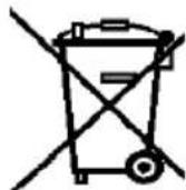
According to the European Directive 2002/96/EC, power tools that are no longer serviceable, and according to the European Directive 2006/66/EC, defective or used rechargeable batteries/batteries must be collected separately and recycled in an environmentally sound manner.
Return unusable rechargeable batteries/batteries directly to:
Germany
Stiftung
GRS Batterien
Heidenkampsweg 44
20097 Hamburg
Germany
Rechargeable batteries/batteries:
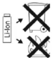
Li-Ion:
Please comply with the information in Section "Transport", page 25.
Subject to changes.
8 Troubleshooting

Danger
Determining the causes for existing defects and eliminating these always requires increased attention and caution. Unplug the rechargeable battery beforehand!
Some of the most frequent defects and their causes are listed in the following chart. In case of other defects, please contact your dealer or the MAFELL customer service directly.
| Defect | Cause | Elimination |
| Machine cannot be switched on. | Discharge the rechargeable battery. | Charge the rechargeable battery. |
| Rechargeable battery not engaged in end position. | Insert the rechargeable battery correctly and ensure it is properly seated. | |
| The electronic signal indicator lights up permanently. | Rechargeable battery is almost empty.The electronic system protects the rechargeable battery from deep discharge. | To check its state of charge, press the button on the rechargeable battery.If only one LED is on, recharge the rechargeable battery. |
| Temperature is too high. | Allow the machine and the rechargeable battery to cool down. | |
| The restart protection prevents the machine from starting. | Switch the machine off and on again. If the battery is inserted while the machine is switched on, the machine will not start. | |
| The electronic signal indicator lights up permanently. | Overloading of the machine during operation. Performance may be reduced. | Reduce the working pressure. |
| The machine switches off at a sudden increase in load. | With a sudden increase in load, the required current also rises sharply. This rise in current, which occurs when there is a sudden blockage or backlash, is measured and then leads to the machine being switched off. | Switch the machine off and on again. You can continue working normally. Try to avoid further blockages. |
| Sudden smoke emission from the motor casing | Overload of the machine's electronic system | Interrupt the power supply by removing the battery pack. The smoke emission stops.Do not insert a rechargeable battery! Avoid inhaling the smoke! |
| Machine stops. | When the machine is overloaded, the restart protection is triggered. | Switch machine off and on again |
| Milling cutter jams as the machine is advanced. | Blunt milling cutter | Switch off the machine immediately.Remove the machine from the workpiece and replace the milling cutter.Replace the indexable cutting inserts. |
| Burn marks on the milled surfaces. | The milling cutter is unsuitable for the operation or blunt. | Replace the indexable cutting inserts.Replace the milling cutter |
| Chip ejection blocked | Wood is too damp | Clean chip ejectionUse dry wood |
| Extended milling without extraction | Connect machine to an external extraction system |
9 Optional accessories
- Reversible scoring knives for milling head Order No. 034907
- Rechargeable battery PowerTank 18 M 72 LiHD Order No. 094500
- Rechargeable battery PowerTank 18 M 72 LiHDX Order No. 094523
- Rechargeable battery PowerTank 18 M 99 LiHD Order No. 094503
- Rechargeable battery PowerTank 18 M 144 LiHD Order No. 094498
- Rechargeable battery PowerTank 18 M 144 LiHDX Order No. 094520
10 Exploded drawing and spare parts list
The corresponding information in respect of spare parts can be found on our homepage: www.mafell.com
Sommaire
natural_image
3D mechanical component diagram with dimension label '6' and directional arrow, no readable text or symbols beyond the number and identifierIII. 5
III. 7
natural_image
Technical illustration of a mechanical component with directional arrows indicating rotation or assembly (no text or symbols present)Fig. 3
natural_image
3D mechanical component diagram with dimension label '6' and directional arrow (no readable text or symbols)MAF02399/a
Fig. 5
natural_image
3D mechanical assembly diagram showing a component with numbered parts (2 and 10) and no readable text or symbols.Fig. 7
natural_image
3D mechanical component diagram with dimension label '6' and directional arrow, no readable text or symbols beyond the labelAfb. 5
Afb. 7
7.5 Afdanking accu's/batterijen

natural_image
Technical illustration of a mechanical component with directional arrows indicating motion or assembly (no text or symbols present)Fig. 3
natural_image
3D mechanical component diagram with dimension label '6' and directional arrow, no readable text or symbols beyond labelsFig. 5
Fig. 7
natural_image
Technical diagram of a mechanical component with directional arrows indicating motion or assembly (no readable text or symbols)Kuva 3
Kuva 7
natural_image
3D mechanical component diagram with dimension label '6' and directional arrow, no readable text or symbols beyond the number and identifierBild 5
Bild 7
natural_image
3D mechanical component diagram showing a curved assembly with directional arrows, no readable text or symbols present.Fig. 3
natural_image
3D mechanical assembly diagram showing a component with numbered parts (2 and 10) and no readable text or symbols beyond labelsFig. 7
natural_image
Technical illustration of a mechanical component with directional arrows indicating motion or assembly (no text or symbols present)Puc. 3
natural_image
3D mechanical component diagram with dimension label '6' and directional arrow (no readable text or symbols)MAF02399/a
Puc. 5
Puc. 7
natural_image
Mechanical component diagram showing a cylindrical assembly with a curved arrow indicating rotation or movement (no text or symbols present)Rys. 3
natural_image
3D mechanical component diagram with dimension label '6' and directional arrow, no readable text or symbols beyond the labelRys. 5
Rys. 7
natural_image
3D mechanical component diagram showing a cylindrical assembly with directional arrows indicating rotation or movement (no text or symbols present)Obr. 3
natural_image
Mechanical component diagram showing a shaft with a labeled dimension (6) and an arrow indicating direction, no readable text or symbols present.Obr. 5
natural_image
3D mechanical assembly diagram showing a component with numbered parts (2 and 10) and no readable text or symbols beyond labelsObr. 7
7 Servis a opravy

Nebezpečí
natural_image
3D mechanical component with directional arrow indicating rotation or assembly (no text or symbols)Sl. 3
5.3 Akumulator – stanje napolnjenosti in prikaz signalov
Če želite preveriti stanje napolnjenosti baterije, pritisnite tipko na akumulatorju. Odčitajte stanje napolnjenosti na LED-lučkah.
Če je akumulator skoraj prazen, utripa ena LED-lučka. Znova napolnite akumulator.
natural_image
Mechanical component diagram showing a shaft with a labeled dimension (6) and an arrow indicating direction, no readable text or symbols present.Sl. 5
Ker gre za stikalo brez aretirnega mehanizma, stroj teče le tako dolgo, dokler pritiskate na pritisno stikalo.
Sl. 7
Obr. 7
7 Údržba a opravy

Nebezpečenstvo
MAFELL AG
Beffendorfer Straße 4, D-78727 Oberndorf / Neckar
Telefon +49 (0)7423/812-0
Internet:
E-Mail:
Fax +49 (0)7423/812-218
www.mafell.de
mafell@mafell.de
- WARNUNG
- AVERTISSEMENT
- GB · EC Declaration of Conformity
- Signs and symbols
- Product information
- Manufacturer's data
- Information on the rechargeable battery
- Machine identification
- Cordless Alliance System (=CAS) is a cross-manufacturer battery pack system.
- Further information is available at www.cordless-alliance-system.com
- Technical data
- Emissions
- Danger
- Noise emission specifications
- Vibration specifications
- Scope of supply
- Intended use
- Residual risks
- Safety instructions
- General instructions:
- Instructions on the use of personal protective equipment:
- Instructions on operation:
- Instructions on service and maintenance:
- Layout
- Depicted components
- Setting / adjustment
- Charging the rechargeable battery
- Explosion hazard
- Rotatable rechargeable battery
- Battery charge level and signal display
- Fitting the rechargeable battery
- Removing the rechargeable battery
- Chip extraction
- Changing the cutter
- Changing the indexable cutting insert
- Follow the procedure below:
- Operation
- General
- Switching on and off
- Work instructions
- Flush milling
- Service and maintenance
- Machine
- Cutter
- Storage
- Transport
- Disposal of rechargeable batteries/batteries
- For EU countries only:
- Germany
- Rechargeable batteries/batteries:
- Subject to changes.
- Troubleshooting
- Optional accessories
- Exploded drawing and spare parts list
- Sommaire
- Afdanking accu's/batterijen
- Servis a opravy
- Nebezpečí
- Akumulator – stanje napolnjenosti in prikaz signalov
- Údržba a opravy
- Nebezpečenstvo
Brand : Mafell
Model : PF 80-18 PURE
Category : Plane