TE-SY 18/90 Li - Paint spray EINHELL - Free user manual and instructions
Find the device manual for free TE-SY 18/90 Li EINHELL in PDF.

| Product type | Cordless paint spray gun |
| Brand | Einhell |
| Model | TE-SY 18/90 Li |
| Supply voltage | 18 V (DC) |
| Max. flow rate | 1000 ml/min |
| Tank volume | 1200 ml |
| Nozzle diameters | 1.5 mm (grey), 2.5 mm (black), 3.0 mm (white) |
| Max. viscosity | 90 DIN-sec |
| Protection class | III |
| Weight (without battery) | 2.7 kg |
| Sound pressure level | 78.1 dB(A) |
| Sound power level | 89.1 dB(A) |
| Vibration emissions | 0.5 m/s² (uncertainty K=1.5 m/s²) |
| Sprayable materials | Paints, varnishes, stains, lacquers, primers, wood preservatives |
| Non-sprayable materials | Products containing soda, acids, particulates, latex, anti-drip paints |
| Delivery contents | Spray gun, 3 nozzles, viscosity cup, tank, cap, air hose, shoulder strap, cleaning needle, adapter, brush, instruction manual |
| Intended use | Spraying of water-soluble or solvent-based paints |
| Cleaning | Immediately after use with solvent or water; clean nozzle, air cap, needle, filter |
| Safety | Wear dust mask, safety goggles, gloves, ear protection |
| Wear parts | Battery, nozzle |
| Warranty | 2 years |
Frequently Asked Questions - TE-SY 18/90 Li EINHELL
User questions about TE-SY 18/90 Li EINHELL
0 question about this device. Answer the ones you know or ask your own.
Ask a new question about this device
Download the instructions for your Paint spray in PDF format for free! Find your manual TE-SY 18/90 Li - EINHELL and take your electronic device back in hand. On this page are published all the documents necessary for the use of your device. TE-SY 18/90 Li by EINHELL.
USER MANUAL TE-SY 18/90 Li EINHELL
GB Original operating instructions Cordless paint spray system
natural_image
Close-up of a mechanical device with labeled parts (8 and 14), no visible text or symbols beyond labels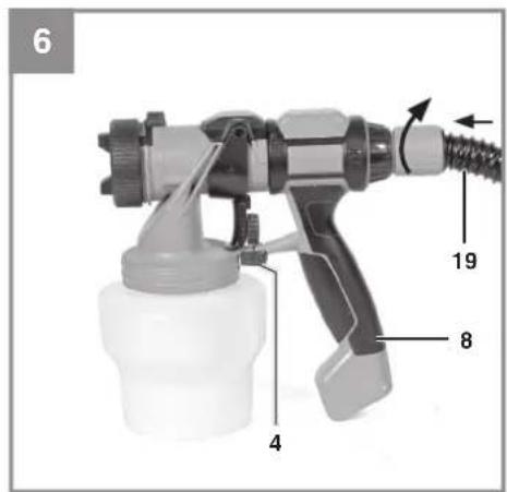

natural_image
Hand holding a spray gun with a white hose and nozzle, labeled with number 11 (no text or symbols on the weapon itself)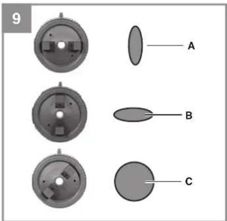
natural_image
Close-up of a spray gun with a handle and nozzle, showing no text or symbols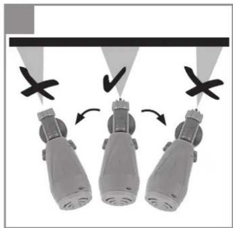
natural_image
Three identical mechanical devices with arrows indicating motion or assembly, no visible text or symbols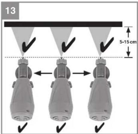
natural_image
Close-up of a hand using a spray gun to adjust or install a mechanical component (no visible text or symbols)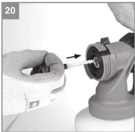
natural_image
Close-up of hands using a tool to adjust or install a mechanical component (no visible text or symbols)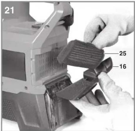
natural_image
Close-up of a mechanical device with labeled parts (23, 24, 23, 22), no readable text or symbols beyond labels24

flowchart
graph TD
    A["1: Person using device"] --> B["2: Head with headphones"]
    B --> C["3: Handheld hand, wearing mask"]
    C --> D["4: Headless worker wearing mask"]
    D --> E["5: Hand with gloves"]
    E --> F["6: Handheld hand, using a device"]
    F --> G["7: Temperature monitoring diagram with +40°C and +10°C indicators"]
-7-
D
Gefahr!
When using the equipment, a few safety precautions must be observed to avoid injuries and damage. Please read the complete operating instructions and safety regulations with due care. Keep this manual in a safe place, so that the information is available at all times. If you give the equipment to any other person, hand over these operating instructions and safety regulations as well. We cannot accept any liability for damage or accidents which arise due to a failure to follow these instructions and the safety instructions.
Explanation of the symbols used (see Fig. 24)
- Danger! - Read the operating instructions to reduce the risk of injury.
- Caution! Wear ear-muffs. The impact of noise can cause damage to hearing.
- Caution! Wear a dust mask. Harmful mist can form when processing paints and lacquers. Note the information provided by the manufacturer of the materials you are processing. Use suitable safety masks to protect yourself.
- Caution! Wear safety goggles. Note the information provided by the manufacturer of the materials you are processing. Wear suitable eye protection (goggles) to protect yourself.
- Caution! Wear gloves.
- Note! Disassemble and clean the equipment immediately after each use. This is the only way to keep the wetted parts clean and prevent clogging. Parts that are not cleaned can become clogged, causing an equipment fault.
- Store the batteries only in dry rooms with an ambient temperature of +10°C to +40°C. Place only fully charged batteries in storage (charged at least 40%).
1. Safety regulations
The corresponding safety information can be found in the enclosed booklet.
Danger!
Read all safety regulations and instructions. Any errors made in following the safety regulations and instructions may result in an electric shock, fi re and/or serious injury.
Keep all safety regulations and instructions in a safe place for future use.
2. Layout and items supplied
2.1 Layout (Fig. 1-4, 14, 17, 21-23)
- Union nut
- Air cap
- 3.0 mm nozzle
- Locking lever
- Trigger
- Control screw for paint volume
- Control lever for air volume
- Handle
- Viscosity cup
- Riser pipe seal
- Riser pipe
- Container
- Fluid needle (plastic)
- Trigger unit
- Drive unit
- Filter cap
- Shoulder strap
- On/Off switch
- Air hose
- 1.5 mm nozzle
- 2.5 mm nozzle
- Air pipe
- Seal cap
- Seal
- Air inlet filter
A. Cleaning needle
B. Fluid needle adapter
C. Cleaning brush
a. Battery charge level indicator
b. Battery charge level indicator (LEDs)
c. Pushlock button
d. Li-ion battery pack
(not supplied with this product)
e. Power X-Charger
(not supplied with this product)
2.2 Items supplied
Please check that the article is complete as specified in the scope of delivery. If parts are missing, please contact our service center or the sales outlet where you made your purchase at the latest within 5 working days after purchasing the product and upon presentation of a valid bill of purchase. Also, refer to the warranty table in the service information at the end of the operating instructions.
- Open the packaging and take out the equipment with care.
- Remove the packaging material and any packaging and/or transportation braces (if
GB
available).
- Check to see if all items are supplied.
- Inspect the equipment and accessories for transport damage.
- If possible, please keep the packaging until the end of the guarantee period.
Danger!
The equipment and packaging material are not toys. Do not let children play with plastic bags, foils or small parts. There is a danger of swallowing or suffocating!
- Shoulder strap
• 1.5 mm nozzle (colour: grey)
• 2.5 mm nozzle (colour: black)
3.0 mm nozzle
(fitted to the tool, colour: white) - Viscosity cup
- Container
• Cap for the container
Air hose
• Original Operating Instructions
• Safety Information
3. Proper use
The machine is suitable for spraying solvent-borne and water-borne paint, varnish, primers, transparent lacquer, vehicle basecoats and clearcoats, stains and wood preservatives. It must not be used for alkaline solutions, acidic solutions, particle-containing spraying substances, latex paints, and paints containing spray or drip inhibitors.
The equipment is to be used only for its prescribed purpose. Any other use is deemed to be a case of misuse. The user / operator and not the manufacturer will be liable for any damage or injuries of any kind caused as a result of this.
Please note that our equipment has not been designed for use in commercial, trade or industrial applications. Our warranty will be voided if the machine is used in commercial, trade or industrial businesses or for equivalent purposes.
4. Technical data
Motor power supply .... 18 V DC Max. flow rate .... 1000 ml/min Container volume .... 1200 ml
Nozzle ∅ ....1.5 / 2.5 / 3.0 mm Max. viscosity ....90 DIN-sec Protection class ....III Weight without battery ....2.7 kg
Danger!
Sound and vibration
Sound and vibration values were measured in accordance with EN 62841-1.
L_nA sound pressure level ..... 78.1 dB(A)
K_nA uncertainty 3 dB
L_WA sound power level 89.1 dB(A)
K_WA uncertainty 3 dB
Wear ear-muff s.
The impact of noise can cause damage to hearing.
Total vibration values (vector sum of three directions) determined in accordance with EN 62841-1.
Handle
Vibration emission level a_n = 0.5m / s^2
Uncertainty K = 1.5 m/s²
The specified vibration value was established in accordance with a standardized testing method. It may change according to how the electric equipment is used and may exceed the specified value in exceptional circumstances.
The specified vibration value can be used to compare the equipment with other electric power tools.
The specified vibration value can be used for initial assessment of a harmful effect.
Keep the noise emissions and vibrations to a minimum.
- Only use appliances which are in perfect working order.
• Service and clean the appliance regularly.
• Adapt your working style to suit the appliance.
• Do not overload the appliance. - Have the appliance serviced whenever necessary.
- Switch the appliance off when it is not in use.
• Wear protective gloves.
GB
Caution!
Residual risks
Even if you use this electric power tool in accordance with instructions, certain residual risks cannot be rules out. The following hazards may arise in connection with the equipment's construction and layout:
- Lung damage if no suitable protective dust mask is used.
- Damage to hearing if no suitable ear protection is used.
5. Before starting the equipment
Warning!
Always remove the battery pack before making adjustments to the equipment.
5.1 Charging the LI battery pack (Fig. 1d, 2-3)
- Remove the battery pack (d) from the drive unit by pressing the pushlock button (c) downwards.
- Check that your mains voltage is the same as that marked on the rating plate. Insert the power plug of the charger (e) into the mains socket outlet.
- The green LED will then begin to flash.
Push the battery pack onto the battery charger. In section 12 (Charger indicator) you will find a table with an explanation of the LED indicator on the charger.
If the battery pack fails to charge, check for the following:
• voltage at the power socket
- whether there is good contact at the charging contacts of the charging unit
If the battery pack still fails to charge, send
• the charger and charging adapter
• and the battery pack
to our customer service center.
To ensure that items are properly packaged and delivered when you send them to us, please contact our customer service or the point of sale at which the equipment was purchased.
When shipping or disposing of batteries and cordless tools, always ensure that they are packed individually in plastic bags to prevent short circuits and fi res.
To ensure that the battery pack provides long service, you should take care to recharge it promptly. You must recharge the battery pack when you notice that the performance of the device drops. Never allow the battery pack to become fully discharged. This will cause it to develop a defect.
5.2 Battery capacity indicator (Fig. 2/Pos. b) Press the button for the battery capacity indicator (a). The battery capacity indicator (b) shows the charge status of the battery using 3 LEDs.
All 3 LEDs are lit:
The battery is fully charged.
2 or 1 LED(s) are lit:
The battery has an adequate remaining charge.
1 LED fl ashes:
The battery is empty, recharge the battery.
All LEDs blink:
The battery temperature is too high. Remove the battery from the equipment, keep it at room temperature for one day. If the fault reoccurs, this means that the rechargeable battery has undergone exhaustive discharge and is defective. Remove the battery from the equipment. Never use or charge a defective battery.
5.3 Assembling the spray gun (Fig. 4, 5, 6)
Plug the riser pipe (11) with seal (10) onto the trigger unit (14) and then screw the container (12) on the trigger unit. The trigger unit (14) is attached to the handle (8) by means of a bayonet connector. To begin with, hold the trigger unit and the handle (8) at an angle of 90^ ; the correct position is indicated by arrows on both components.
Hold the locking lever (4) open. Twist and insert the trigger unit (14) into the handle. Close the locking lever.
5.4 Fitting the air hose (Fig. 6)
The handle (8) and the air hose (19) are marked with arrows indicating the locking position: Connect – turn counter-clockwise. Disconnect – turn clockwise. Fasten the hose by twisting it into the handle.
Fasten the other end of the hose to the drive unit in the same way.
GB
6. Operation
Warning!
Follow the safety precautions provided by the manufacturer of the material you want to spray. Use suitable face masks, gloves and protective clothing.
6.1 Material preparation
The paint usually has to be thinned before it can be used in the spray gun. Instructions on how to thin the paint for spraying are not always printed on the paint tin. You should use the viscosity table as a guide (viscosity = consistency of the paint).
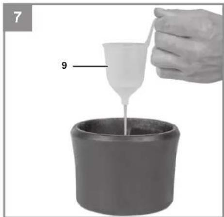
6.1.1 Measuring the viscosity (Fig. 7)
- Mix the material thoroughly before measuring.
- Completely immerse the viscosity cup (8) into the material.
- Then lift the viscosity cup (8) out of the mixture and use a stopwatch to measure the time it takes for all of the material to flow through the cup. As soon as the continuous flow out of the bottom is interrupted, stop the timer. Repeat until you have the viscosity you need.
This is the „Draining time in seconds“. (See 10. Viscosity Table)
6.1.2 Nozzle diameter
The size of the nozzle and the fluid needle to be used depends on the viscosity of the material. Depending on the viscosity, use the 3.0 mm dia. nozzle (colour: white, for high viscosity), or the 2.5 mm dia. nozzle (colour: black, for medium viscosity), or the 1.5 mm dia. nozzle (colour: grey, for low viscosity). The fluid needle in the tool is suitable for all three nozzle diameters.
6.2 Working with the paint spray gun (Fig. 8) Important! Cover all surfaces which must be protected from the spray, even areas which are further away from the place where you are working. A fi ne mist from the spray gun can spread to areas in the wider surroundings indoors and outdoors, and the material will be deposited on surfaces there.
- Unscrew the container (12) from the paint spray gun.
- Align the material tube (11) for the object you are working on.
- Spaying on horizontal objects: Rotate the material tube (11) towards the front.
- Spaying on raised objects: Rotate the materi-
al tube (11) towards the rear.
- Never continue spraying until the container is completely empty. If the material tube no longer reaches the spray material, the spray flow will be interrupted and the coverage on the surface will be uneven.
- Once you have performed the viscosity measurement as described in 6.1.1, place the container (12) on some paper, pour in the material you have prepared and tightly screw the container (12) back into the paint spray gun.
- The paint spray gun is allowed to be placed only on a clean, even surface. Otherwise it might tip over.
- After each cleaning (see 6.6) or change of fan pattern (see 6.3), tighten the air cap retaining ring (1) to prevent material from leaking out between the air cap retaining ring and the air cap (2).
6.3 Adjusting the fan pattern (Fig. 9, 10)
You can set the paint spray gun to produce three different fan patterns to suit your needs.
Loosen the air cap retaining ring (1) and rotate the air cap (2) to the desired position. Re-tighten the air cap retaining ring.
Selecting the fan pattern:
A: vertical fan
-> for horizontal surfaces
B: horizontal fan
-> for vertical surfaces
C: Round cone
-> for corners, edges and surfaces that are diffi cult to access
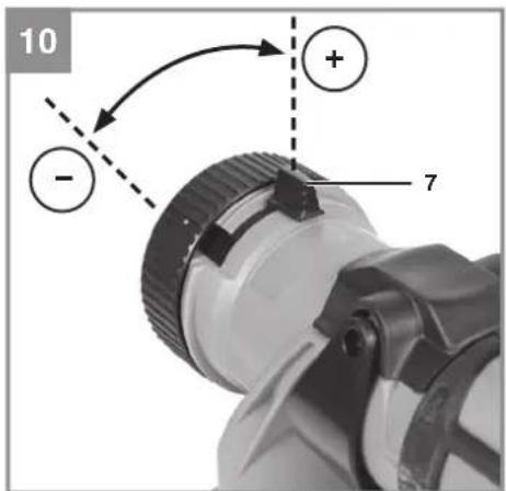
Selecting the air volume
Flat fan: Push the control lever (7) downwards to reduce the air volume > The fl at fan will become narrower and finally dot-shaped.
Solid cone: Push the control lever (7) downwards to reduce the air volume > The solid cone will become wider.
Risk of injury!
Never press the trigger while you are adjusting the jet.
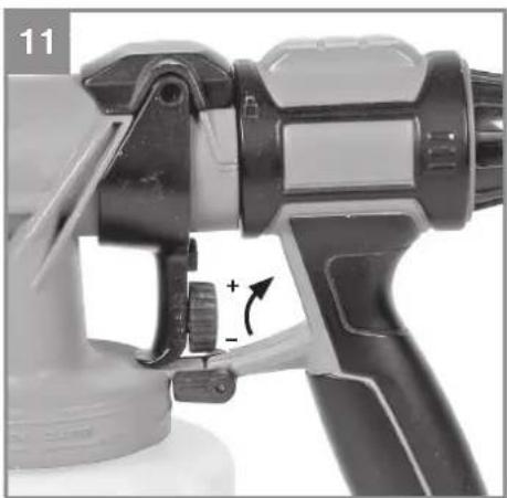
6.4 Adjusting the material flow (Fig. 11)
You can rotate the max. paint volume control (6) to regulate the material flow.
GB
- direction -> lower material flow
- direction -> higher material flow
Note: If you are not yet very familiar with the settings for the spray shape and the material volume, use a test piece to check the results before you paint the actual workpiece.
6.5 Spraying techniques
- The results you get depend on how smooth and clean the surface is. The surface must be carefully prepared and free of dust.
- Surfaces, threads, etc. which should not be sprayed must be covered.
- Always set the spray gun down on cardboard or something similar. You can use the cardboard as a target to properly adjust the spray gun.
Important:
Always begin spraying outside of the area to be sprayed and avoid interrupting spraying inside the area to be sprayed.
- Wrong (Fig. 12): If you only rotate the spray gun from side to side, the gun will produce a heavy mist and the coverage will be uneven.
- Right (Fig. 13): Always hold the spray gun at the same distance (about 5-15 cm) from the surface you are working on.
- Move the spray gun uniformly laterally or up and down depending on the fan pattern.
• Uniform motion of the spray gun produces uniform finish quality. - If material residue remains on the nozzle (3) and the air cap (2), clean both parts with solvent or water.
6.6 Disconnecting and cleaning the gun (Fig. 1a-1d, 14-21, 22a, 22b, 23)
Danger!
Always pull out the battery pack before starting any cleaning work.
- Press the trigger (5), so that the residual material flows back into the container (12).
- Unscrew the container (12) and empty the residual material back into the material tin.
- Clean the container (12) and the material tube (11) with a bristle brush.
- Pour solvent or water into the container. Screw the container back on. Solvents with a flash point above 55^ C are not allowed to be used.
- Reinsert the battery and turn on the paint
spray gun. Set the controller (6) to the maximum flow setting. Spray the solvent or water into a container or rag, but never into the surroundings.
6. Repeat the procedure above until the clear solvent or water exits from the nozzle (3).
7. Then switch off the paint spray gun and remove the battery.
8. Completely empty the container (12). Always keep the container (12) free of residue and check it for damage.
9. Use a rag soaked in solvent or water to clean the outside of the paint spray gun and the container (12).
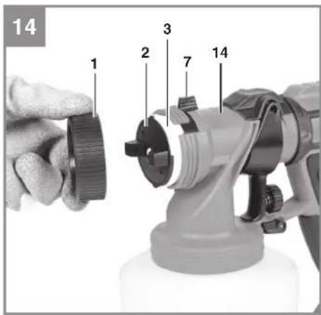
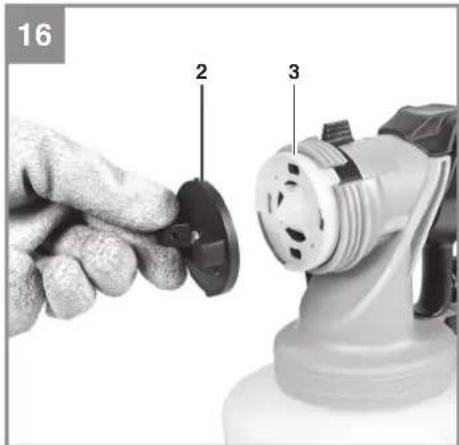
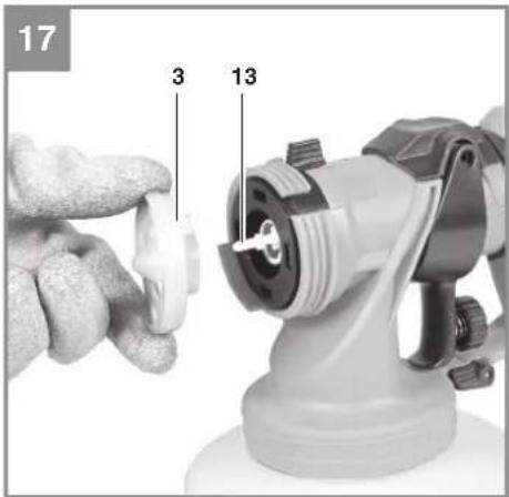
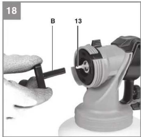
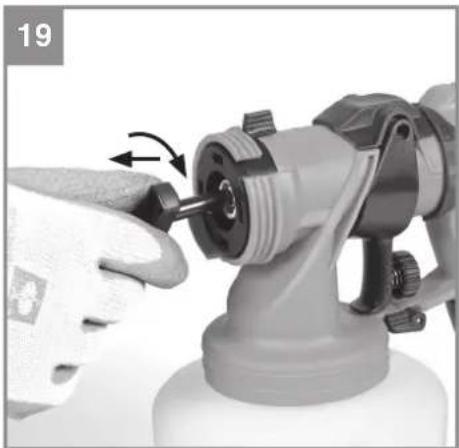
10. Unscrew the air cap retaining ring (1) and then remove the air cap (2). Remove the nozzle (3). Push the fluid needle adapter (B) onto the fluid needle (13). Twist and pull to remove the fluid needle. Clean the air cap retaining ring, the air cap, the nozzle and the fluid needle with a bristle brush and solvent or water.
11. Remove the filter cap (16) in order to clean the air inlet filter (25). Remove the filter and clean it by blowing it out with air. Then reinsert the filter and screw the filter cap onto the tool. Do not operate the tool without the filter (Fig. 21).
12. Reinsert the fluid needle. While inserting, ensure that the pins on the sides of the fluid needle point up/down and not left/right. Use slight pressure to insert the fluid needle until it latches home. (Fig. 20)
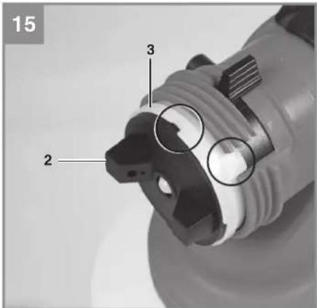
13. Pull the trigger (5) so that the fluid needle moves inwards. Now first place the nozzle (3) on the fluid needle (13) and then the air cap (2) on the nozzle (3). The nozzle has a special locking point on the drive unit, and the air cap has a special locking point on the nozzle (Fig. 15). Use the union nut (1) to screw the air cap to the trigger unit (14) (Fig. 14).
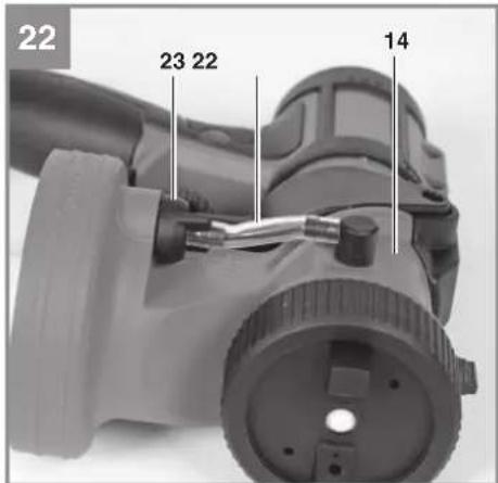
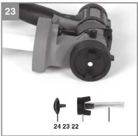
14. Pull the air pipe (23) off the trigger unit (14) and unscrew the seal cap (24) from the trigger unit, then remove the seal (24). Clean the air pipe, the seal and the seal cap as required, then refi t them on the trigger unit (Fig. 22-23).
15. Ensure that the paint spray gun is completely dry before storing it.
16. Properly dispose of residual paint and cleaning agents in accordance with local laws and regulations. Residual paint and solvents must be taken to a suitable collection point. If you are not sure, ask the local council where the nearest collection point is.
GB
Warning!
The trigger unit, the battery and the charger must never be held under water or be immersed in other liquids. Clean the housing only with a dampened cloth.
Note: If you use 2-component paint, you must clean the gun immediately. Otherwise the paint might dry inside the gun, causing an equipment fault.
7. Cleaning, maintenance and ordering of spare parts
Danger!
Always pull out the mains power plug before starting any cleaning work.
7.1 Cleaning
- Keep all safety devices, air vents and the motor housing free of dirt and dust as far as possible. Wipe the equipment with a clean cloth or blow it with compressed air at low pressure.
• We recommend that you clean the device immediately each time you have finished using it. - Clean the equipment regularly with a moist cloth and some soft soap. Do not use cleaning agents or solvents; these could attack the plastic parts of the equipment. Ensure that no water can seep into the device. The ingress of water into an electric tool increases the risk of an electric shock.
7.2 Maintenance
There are no parts inside the equipment which require additional maintenance.
7.3 Ordering spare parts and accessories
Please provide the following information when ordering spare parts:
- Type of unit
• Article number of the unit
• ID number of the unit - Spare part number of the required spare part For our latest prices and information please go to www.Einhell-Service.com
8. Disposal and recycling
The equipment is supplied in packaging to prevent it from being damaged in transit. The raw materials in this packaging can be reused or recycled. The equipment and its accessories are made of various types of material, such as metal and plastic. Never place defective equipment in your household refuse. The equipment should be taken to a suitable collection center for proper disposal. If you do not know the whereabouts of such a collection point, you should ask in your local council offices.
9. Storage
Store the equipment and accessories in a dark and dry place at above freezing temperature. The ideal storage temperature is between 5 and 30
°C. Store the electric tool in its original packaging.
10. Viscosity Table
| Examples of spray materials. Follow the manufacturer's instructions! | Draining time in seconds (DIN-sec) |
| Solvent-borne primers 25-30 | |
| Solvent-borne paint 15-30 | |
| Water-borne primers 25-30 | |
| Water-borne paint 20-25 | |
| Wood preservatives, stains, oils undiluted | |
| Vehicle topcoats 20-25 |
11. Troubleshooting Guide
| Fault Possible cause Remedy | ||
| No material exits from the nozzle | - Nozzle clogged.- Material tube clogged.- Max. paint volume control rotated too far anti-clockwise (-).- Material tube is loose.- No pressure build-up in the container.- Consistency of the material is too thick. | - Clean- Clean- Turn clockwise (+)- Insert- Tighten container- Dilute |
| Material drips from nozzle after spraying | - Nozzle is loose.- Nozzle is worn.- Nozzle seal is worn.- Solids in the air cap or nozzle. | - Tighten- Replace- Replace- Clean |
| Atomization too coarse - Material viscosity too high.- Material volume too high.- Max. paint volume control turned too far clockwise (+).- Dirty nozzle.- Insufficient pressure build-up in the container | - Dilute- Turn the max. paint volume control anti-clockwise (-)- Clean- Tighten the container | |
| Intermittent ("fl uttering") spray | - Almost all of the material in the container has been used up. | - Add more |
| Coating pattern is too light and uneven | - You moved the paint spray gun too fast across the surface you are working on. | - Move the gun more slowly |
| The paint runs | - You applied too much material | - Turn the max. paint volume control anti-clockwise (-) |
| Excessive spray mist | - The gun is too far away from the object you are working on | - Hold the gun closer- Turn the max. paint volume control anti-clockwise (-) |
GB
12. Charger indicator
| Indicator status Explanations and actions | ||
| Red LED Green LED | ||
| Off | Flashing | Ready for useThe charger is connected to the mains and is ready for use; there is no battery pack in the charger |
| On Off Charging | The charger is charging the battery pack in quick charge mode. The charging times are shown directly on the charger.Important! The actual charging times may vary slightly from the stated charging times depending on the existing battery charge. | |
| Off | On | The battery is charged and ready for use. (READY TO GO)The unit then changes over to gentle charging mode until the battery is fully charged.To do this, leave the rechargeable battery on the charger for approx. 15 minutes longer.Action:Take the battery pack out of the charger. Disconnect the charger from the mains supply. |
| Flashing Off | Adapted charging | The charger is in gentle charging mode.For safety reasons the charging is performed less quickly and takes more time. The reasons can be:- The rechargeable battery has not been used for a very long time.- The battery temperature is outside the ideal range.Action:Wait for the charging to be completed; you can still continue to charge the battery pack. |
| Flashing Flashing Fault | Charging is no longer possible. The battery pack is defective.Action:Never charge a defective battery pack.Take the battery pack out of the charger. | |
| On On Temperature fault | The battery pack is too hot (e.g. due to direct sunshine) or too cold (below 0^ ).Action:Remove the battery pack and keep it at room temperature (approx. 20^ ) for one day . | |
GB

For EU countries only
Never place any electric power tools in your household refuse.
To comply with European Directive 2012/19/EC concerning old electric and electronic equipment and its implementation in national laws, old electric power tools have to be separated from other waste and disposed of in an environment-friendly fashion, e.g. by taking to a recycling depot.
Recycling alternative to the return request:
As an alternative to returning the equipment to the manufacturer, the owner of the electrical equipment must make sure that the equipment is properly disposed of if he no longer wants to keep the equipment. The old equipment can be returned to a suitable collection point that will dispose of the equipment in accordance with the national recycling and waste disposal regulations. This does not apply to any accessories or aids without electrical components supplied with the old equipment.
Please note that batteries and lamps (e.g. light bulbs) must be removed from the tool before it is disposed of.
The reprinting or reproduction by any other means, in whole or in part, of documentation and papers accompanying products is permitted only with the express consent of the Einhell Germany AG.
Subject to technical changes
GB
Service information
We have competent service partners in all countries named on the guarantee certificate whose contact details can also be found on the guarantee certificate. These partners will help you with all service requests such as repairs, spare and wearing part orders or the purchase of consumables.
Please note that the following parts of this product are subject to normal or natural wear and that the following parts are therefore also required for use as consumables.
| Category Example | |
| Wear parts* Battery | |
| Consumables* Nozzle | |
| Missing parts |
* Not necessarily included in the scope of delivery!
In the effect of defects or faults, please register the problem on the internet at www.Einhell-Service.com. Please ensure that you provide a precise description of the problem and answer the following questions in all cases:
• Did the equipment work at all or was it defective from the beginning?
• Did you notice anything (symptom or defect) prior to the failure?
• What malfunction does the equipment have in your opinion (main symptom)?
Describe this malfunction.
GB
Warranty certifi cate
Dear Customer,
All of our products undergo strict quality checks to ensure that they reach you in perfect condition. In the unlikely event that this equipment develops a fault, please contact our service department at the address shown on this guarantee card. You can also contact us by telephone using the service number shown. Please note the following terms under which guarantee claims can be made:
-
These guarantee terms apply solely to consumers, i.e. natural persons, who do not want to use this product in connection with either their commercial or other self-employed activities. These guarantee terms regulate additional guarantee services which the undermentioned manufacturer promises to buyers of its new products in addition to their statutory rights of guarantee. Your statutory rights of guarantee are not affected by this guarantee. Our guarantee is free of charge to you.
-
The guarantee services cover only defects due to material or manufacturing faults on the new product which you have bought in the European Union from the undermentioned manufacturer and are limited to either the rectification of said defects or the replacement of the product, whichever we prefer. Please note that only equipment under the brand name "Professional" has been designed for use in commercial, trade or professional applications. For all other products the guarantee is invalidated if the equipment is used within the guarantee period in commercial, trade or industrial applications or for other equivalent activities.
-
Our guarantee does not cover:
-
Damage to the equipment caused by failure to comply with the installation/assembly instructions or by unprofessional installation; damage caused by failure to comply with the operating instructions (e.g. connection to the wrong mains voltage or current type); damage caused by failure to comply with the maintenance and safety regulations; damage caused by exposing the equipment to abnormal environmental conditions; damage resulting from poor care and maintenance.
- Damage to the equipment caused by misuse or incorrect applications (e.g. overloading the equipment or using non-approved attachments or accessories); damage caused by foreign bodies (e.g. sand, stones, dust, ....) getting inside the equipment. Damage in transit; damage caused by force or external influences (e.g. by dropping the equipment).
-
Damage to the equipment or parts of the equipment which is owed to use-related, normal or otherwise natural wear. For example, batteries and battery packs are manufactured with a cycle limit for design-related reasons. Wear is negatively influenced in particular by load demands and charging speeds as well as exposure to heat, cold, vibration and impact.
-
The guarantee is valid for a period of 2 years starting from the purchase date of the equipment. Guarantee claims must be submitted before the end of the guarantee period and within two weeks of the defect being noticed. No guarantee claims will be accepted after the end of the guarantee period. The original guarantee period remains applicable to the equipment even if repairs are carried out or parts are replaced. In such cases, the work performed or parts fitted will not result in an extension of the guarantee period, and no new guarantee will become active for the work performed or for any replacement parts fitted. This also applies if on-site service is used.
-
To assert your guarantee claim, register the defective equipment at: www.Einhell-Service.com. You will need to provide proof of purchase of the new item of equipment. Equipment returned without such proof or without a rating plate are excluded from the guarantee services because of the lack of traceability. If the defect is covered by our guarantee, then either the item in question will be repaired immediately and returned to you or we will send you a new replacement.
-
If you have taken the equipment with you to a different EU country than where you bought it, we will arrange for a local service partner to provide the guarantee services. If you take the equipment outside the EU, the guarantee will not apply.
Of course, we are also happy to offer a chargeable repair service for any defects which are not covered or no longer covered by the scope of this guarantee. To take advantage of this service, please send the equipment to our service address. We draw attention to the restrictions of this guarantee concerning wear parts, consumables and missing parts as presented in the service information included in this operating manual.
Warrantor/ Service:
Einhell UK Ltd, Unit 10, 1st Floor, Champion's Business Park, Arrowe Brook Road, Upton, Wirral, CH49 0UQ
F
Danger!
A: getto diff uso verticale
Negotovost K_WA 3 dB
Sapma K _WA ....3dB
Kulaklık takın.
X 2006/42/EC
Annex IV
Notified Body:
Reg. No.:
□2000/14/EC_2005/88/EC
Annex V
Annex VI
Noise: measured L_WA = dB (A) ; guaranteed L_WA = dB (A)
P = kW; L/∅ = cm
Notified Body:
□2012/46/EU_(EU)2016/1628
Emission No.
Standard references: EN 62841-1; EN 50580; EN IEC 55014-1; EN IEC 55014-2
Subject to change without notice
Archive-File/Record: NAPR024946
Documents registrar: Siegfried Roider
Wiesenweg 22, D-94405 Landau/Isar
* G3 Cordless peint spray system - F Sisterna de pulverisation de peniture sense fil - I Sistema a spruzzo a batteria - DKN Akku-farvesprisjekte system - S Batteridireltrifte rapurstningsystem - CZ Akumulatory atlikso system - SK Akumulatorov system pre nástrek farnek - NL Acu vertapura system - C Sistema pulverzadora de pinture inelamorto - FN Akku-maalitrujserjesteim - SLO Akumulatorski system za prjenice barve - H Akkus-Festfekzro rendszer - RO System de pulverzarea pentru vopsee ou acumulator - OR Zukturnu jokcounju bochne, je umotropa - P Sistema de pulverazarea de tintas sem filo - HR/8H Akumulatorski sustev za rasprisivanje boje - RS Akumulatorski system za rasprisivanja boje - PL Akumulatorski system natrylskowy do tarb-TR Akul Bcya sprety tebanoca - RUS Akumulatorrana Sisterna Roselysinna Krasin - RE Akuga variphrustusistemi - LV Akumulatoru krasas smizdinatas sistema - LT Akumulatorine danlj purškimo system - GB Serol sistema za bongivizane a cinkumorator - UKR Akumulatorrata system diny rupiszinna jarib - MK Barprisini system da prnaka se boja

Declaration of conformity
We, Einhell UK Ltd
Champions Business Park, First Floor Unit 10, Arrowe Brook Rd, Upton, Wirral CH49 0AB, United Kingdom
declare the conformity to UK standards and legislation was assessed for:
Cordless Paint Spray System TE-SY 18/90 Li (Einhell)
UK legislation
□ Simple Pressure Vessels (Safety) Regulation
X Electrical Equipment (Safety) Regulation
□ Radio Equipment Regulation
□ Personal Protective Equipment Regulation
☐ The Ecodesign for Energy-Related Products and Energy Information Regulation
X The Restriction of the Use of Certain Hazardous Substances in Electrical and Electronic Equipment Regulation
□ Noise Emission in the Environment by Equipment for use Outdoors Regulation
X Electromagnetic Compatibility Regulation
□ Measuring Instruments Regulation
□ Pressure Equipment (Safety) Regulation
Annex V
Annex VI
Noise:measuredL WA = dB (A); guaranteed L WA = dB (A)
P = kW; L/∅ = cm
UK Approved Body:
X Supply of Machinery (Safety) Regulation
Annex IV
UK Approved Body:
UKTE Certifi cate No.:
Standards: BS EN 62841-1; BS EN 50580; BS EN IEC 55014-1; BS EN IEC 55014-2
Wirral, 2023.26.10

Tom Chambers, Managing Director Einhell UK Ltd.
Archive-File/Record: NAPR024946
Article Number: 42.600.40 I.-No.: 21013
Subject to change without notice Wiesenweg 22, 94405 Landau/Isar, Germany
Documents registrar: Siegfried Roider
EH 10/2023 (01)