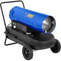
GH-BD-40000GQ - Heating MSW - Free user manual and instructions
Find the device manual for free GH-BD-40000GQ MSW in PDF.

| Product type | LPG heater (propane/butane) |
| Model | MSW-GH-BD-40000GQ |
| Appliance category | I_3B/P (forced ventilation gas convector) |
| Fuel consumption | G30 (butane): 2181 g/h; G31 (propane): 2142 g/h |
| Gas supply pressure | 700 mbar |
| Voltage / Frequency | 230 V~ / 50 Hz |
| Protection class | I (mandatory earthing) |
| Electrical power | 80 W |
| Nominal power | 40 kW |
| Airflow rate | 600 m³/h |
| Ignition | Automatic with room thermostat and RESET button |
| Ventilation mode | Yes, without gas (fan position I) |
| Use | Outdoors or well-ventilated areas (minimum volume 100 m³) |
| Required ventilation | 25 cm² per kW of power, minimum 250 cm², distributed floor/ceiling |
| Safety clearances | Front: 3.5 m; sides/back/top: 2 m; above: 2.5 m |
| Safety devices | Safety thermostat, solenoid valve, flame detection, leak protection |
| Maintenance | Cleaning with compressed air; annual inspection by qualified technician |
| Spare parts | Gas hose, regulator, solenoid valve, electrode, thermocouple (original replacements) |
| Repairability | Repairs reserved for qualified personnel |
| Special features | Possibility to connect two bottles to prevent icing |
| Supply | LPG bottle with supplied regulator; 230 V socket |
Frequently Asked Questions - GH-BD-40000GQ MSW
User questions about GH-BD-40000GQ MSW
0 question about this device. Answer the ones you know or ask your own.
Ask a new question about this device
Download the instructions for your Heating in PDF format for free! Find your manual GH-BD-40000GQ - MSW and take your electronic device back in hand. On this page are published all the documents necessary for the use of your device. GH-BD-40000GQ by MSW.
USER MANUAL GH-BD-40000GQ MSW
natural_image
Line drawing of a portable air purifier with control panel and attached hose (no text or symbols)Einrichtung
natural_image
Line drawing of three cylindrical tanks connected to a portable air vent (no text or symbols)Abbildung. 2
natural_image
Simple line drawing of a wall-mounted device with wires, no text or symbols presentAbbildung. 3
natural_image
Line drawing of a control panel with two digital displays and a rotary knob (no text or symbols)Abbildung. 4
This User Manual has been translated using machine translation. We have made every effort to ensure the translation is accurate, but please note that automated translations are not perfect and are not meant to replace human translators. The official version of the User Manual is in English. Any differences between the translated version and the original English are not legally binding. If you have any questions about the accuracy of the translation, please refer to the English version, which is the official reference.
Technical data
| Parameter description | Parameter value | ||
| Product name | LPG heater | ||
| Model | MSW-GH-BD-20000GQ | MSW-GH-BD-40000GQ | MSW-GH-BD-60000GQ |
| Appliance category | I_3B/P | ||
| Fuel consumption [g/h] | G30: 1090; G31: 1071 | G30: 2181; G31: 2142 | G30: 3636; G31: 3570 |
| Gas supply pressure [mbar] | 700 | 700 | 500 |
| Voltage [V~] / Frequency [Hz] | 230 / 50 | ||
| Protection Class | I | ||
| Electrical power [W] | 40 | 80 | 80 |
| Rated power [kW] | 20 | 40 | 60 |
| Air flow [ m^3/h ] | 320 | 600 | 872 |
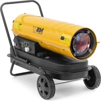
Purpose
The LPG (Liquefied Petroleum Gas) heater is used to provide efficient, portable, and powerful heating by burning LPG fuel (such as propane or butane).
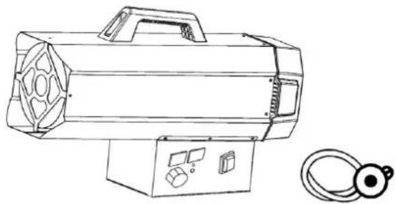
Overview
natural_image
Line drawing of a portable air purifier with control panel and attached cable (no text or symbols)Installation
- Connect the product to a suitable electric socket (230V\~50Hz).
- Ensure that the machine is properly earthed.
-
Connect the gas supply hose to the pressure regulator, and then attach the regulator to a suitable LPG cylinder.
-
Open the cylinder tap and check the supply hose and fittings for gas leaks. It is recommended to use an approved leak detector for this process.
- NEVER USE NAKED FLAMES to check for leaks.
- For automatic models, connect the room thermostat to the socket on the appliance and set it to the required temperature.
Usage

NOTE
- Use only in well-ventilated areas and keep the appliance away from combustible materials.
• After use, turn off the gas supply at the cylinder valve.
• Ensure that the fan is operating correctly before lighting the burners. - This appliance can be used by children aged 8 years and above, as well as by persons with reduced physical, sensory, or mental capabilities, or those lacking experience and knowledge, if they are supervised or properly instructed in using the appliance safely and understand the hazards involved.
- Cleaning and user maintenance must not be performed by children without supervision.

WARNING
• To prevent overheating, do not cover the product.
- Some parts of this product can become very hot and may cause burns. Special care should be taken when children and vulnerable people are present.
Safety Clearance
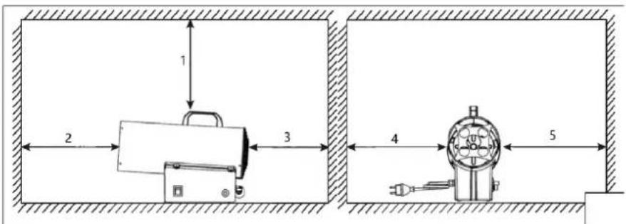
Figure. 1
1- Min. 2 m
2- Min. 3.5 m
3- Min. 2.5m
4- Min. 2 m
5- Min. 2 m
General instructions
• The product must only be operated outdoors or in well-ventilated areas.
- For every kilowatt (KW) of heater power, there must be a permanent ventilation area of 25 cm^3 . This ventilation should be evenly split between floor and ceiling levels, with a minimum total outlet of 250 cm^3 to ensure safe operation and avoid gas accumulation.
- Never point the product's hot air flow towards the gas cylinder.
- Only use the pressure regulator that comes with the product.
• The product must always have its cover in place while in use. - The product should not be used in spaces where the heat exceeds 100W per cubic meter of room volume. The room must have a minimum volume of at least 100m^3 .
• The air inlet and outlet sections of the product should never be blocked or obstructed. - If the product runs at maximum capacity for extended periods, ice may form on the gas cylinder due to excessive vapor withdrawal. However, the cylinder should never be heated to address this issue. To avoid or reduce this effect, a larger cylinder or two linked cylinders should be used (see Figure 2).
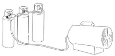
natural_image
Line drawing of three cylindrical containers connected to a portable device with a coiled cable (no text or symbols)Figure. 2
- The product should not be used in cellars, basements, or any room below ground level.
- If the product malfunctions, you should immediately contact a qualified technical assistance service.
• After using the product, always turn off the gas cylinder tap. - When replacing the gas bottle, always follow safety rules and perform the replacement away from any possible sources of ignition to avoid accidents.
• The gas hose must remain straight and untwisted. - The product must be positioned where there is no risk of fire. Specifically, the hot air outlet must be at least 3 meters away from any flammable walls or ceilings. Additionally, the hot air should never be directed toward the gas bottle to avoid overheating.
- Only use the original manufacturer's gas hose and spare parts.
- If you detect or suspect a gas leak, immediately close the gas cylinder and turn off the product. Do not use the product again until it has been inspected by a qualified service center. If the product is indoors, ensure proper ventilation by fully opening doors and windows. Avoid creating sparks or using open flames in the area until the issue is resolved.
Preparing for operation
- Inspect the product for any possible shipping damage before use.
- Connect the hose and regulator assembly to the LPG cylinder by rotating the nut counterclockwise into the cylinder's valve outlet and tightening it securely.
- Open the cylinder's gas valve and check all gas connections using a soap and water solution to detect any leaks.
- Connect the power cord to a well-grounded 220V\~, 50Hz power source.
Ignition
Ignition/automatic ignition
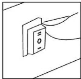
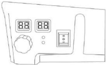
- Turn the power switch to position "I". The motor will start, and the digital display will show the room temperature (see Figure 3).
natural_image
Simple line drawing of a rectangular object with a label 'O' and connecting wires, no text or symbols present.Figure. 3
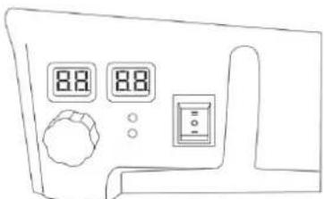
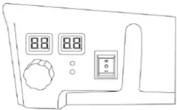
- Open the gas valve and turn the power switch to position "II". The left display window shows the set temperature, and the right window shows the room temperature. The product will automatically ignite when the set temperature is higher than the room temperature (see Figure 4).
natural_image
Line drawing of a control panel with two digital displays and a rotary knob (no text or symbols)Figure. 4
-
Regulate the gas flow pressure according to the desired thermal power by turning the wheel on the pressure reducer. Turn it anticlockwise to increase pressure or clockwise to decrease pressure.
-
If the flame ignites but the product locks after a few seconds, the RESET control lamp will light up. Wait for one minute, then unlock the product by pressing the RESET button and repeat the starting process.
-
If the problem persists, contact your supplier for further assistance.

CAUTION
If ignition is difficult or irregular before repeating the ignition operations make sure that the fan is not locked, and the air inlet and outlet are unobstructed.
Switch Off
To stop the product, follow these steps:
- Shut off the gas cylinder tap.
- Allow the fan to continue running until the flame shuts off completely.
- Once the flame is out, turn the fan switch to position "O".
Air Conditioning
The product can also be used as a ventilator. To use this function, disconnect the gas supply hose and connect the product's plug to a suitable electrical supply. Set the fan switch to position "I" to activate the ventilation mode.

Odor Fade Warning LPG may lose its odor over time, making leaks harder to detect. Do not rely on smell alone to identify gas leaks. Use a gas detector or other approved methods for leak detection. NEVER USE NAKED FLAMES to check for leaks. Failure to detect leaks can lead to fire, explosion, or serious injury.

Asphyxiation Hazard
- Do not use the product for heating human living spaces.
• Do not operate in unventilated areas. - Ensure the flow of combustion and ventilation air is not obstructed.
- Proper ventilation must be provided to meet the combustion air requirements of the product.
• Insufficient ventilation can result in improper combustion. - Improper combustion can lead to carbon monoxide poisoning, which may cause serious injury or death. Symptoms of carbon monoxide poisoning include headaches, dizziness, and difficulty breathing.
Fuel Gas Odor
Both LP (Propane) gas and natural gas have man-made odorants added to help detect fuel gas leaks. If a gas leak occurs, you should be able to smell the gas. Since Propane (LP) is heavier than air, be sure to check for the gas odor close to the floor. Any gas odor should prompt you to take immediate action.

LP Gas and Natural Gas Odor Warning
- Avoid any actions that could ignite the gas.
• Do not operate any electrical switches. - Do not unplug power cords or use extension cords.
- Avoid lighting matches or any other flame sources.
• Do not use your telephone.
• Get everyone out of the building and away from the area. - Close all propane (LP) gas tank or cylinder valves, or the main fuel supply valve located at the meter if you use natural gas.
- Since propane (LP) gas is heavier than air, it can settle in low areas. Avoid entering low areas if you suspect a propane leak.
- Use a neighbor's phone to contact your fuel gas supplier and the fire department. Do not reenter the building.
- Remain outside and away from the area until the firefighters and your fuel gas supplier declare it safe.
- Allow the fuel gas service person and firefighters to check for gas leaks, ventilate the area, and repair any issues. Only trained professionals should relight the appliance after ensuring safety.
Maintenance
-
Repairs and maintenance should only be carried out by qualified personnel.
-
The unit must be inspected by a qualified technician at least once annually.
-
Regularly inspect the condition of the gas hose and gas regulator. If replacement is necessary, use only the original spare parts.
-
Before performing any maintenance on the product, disconnect it from both the gas supply and electrical supply.
-
If the unit has not been used for an extended period, it is recommended that a technician performs a general check-up before use. This should include the following:
• Periodically inspect the condition of the gas supply hose, and if it needs replacement, use only original spare parts.
• Verify the position of the starting electrode (see Figure 5).
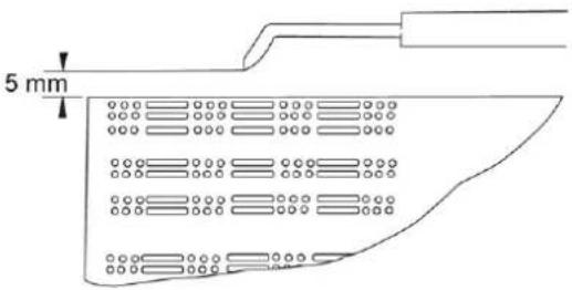
Figure. 5
- Check the connections of the safety thermostat and the thermocouple regularly to ensure they are always clean. If needed, clean the fan blade and the interior of the product using compressed air.
Troubleshooting
Automatic ignition models
| PROBLEM | CAUSES | SOLUTIONS |
| The motor does not work | No electricity supply | Check the terminal board with a tester |
| The room thermostat is set too low | Set the thermostat to a higher temperature | |
| The safety thermostat is activated | Wait about one minute, then press the RESET button | |
| The motor works, but the burner does not light up and after a few seconds the product stops | The cylinder gas tap is closed | Open the gas tap |
| The cylinder is empty | Replace with a new cylinder. | |
| The nozzle is obstructed | Remove and clean the nozzle | |
| The solenoid gas valve is not open | Check if the solenoid valve is functioning | |
| There is no spark | Check the position of the electrode | |
| The burner lights up but after a few | No connection with the earthing system | Verify and connect properly |
| Defective connection between sensor and safety device | Check and connect properly | |
| seconds the product stops | Defective safety device Replace the safety device | |
| The product stops during the operation | Excessive gas supply | Check the pressure reducer and replace it if necessary |
| Insufficient air flow | Check that the motor is working properly | |
| Insufficient gas supply due to ice formation on the cylinder | Check the cylinder and use a larger one, or connect two cylinders together. | |
Disposing of Used Devices
Do not dispose of this device in municipal waste systems. Hand it over to an electric and electrical device recycling and collection point. Check the symbol on the product, instruction manual and packaging. The plastics used to construct the device can be recycled in accordance with their markings. By choosing to recycle you are making a significant contribution to the protection of our environment.
Contact local authorities for information on your local recycling facility.

natural_image
Line drawing of a portable air purifier with control panel and attached cable (no text or symbols)Instalacja
natural_image
Line drawing of a cylindrical device connected to a motor via wires, no text or symbols presentRycina 2
natural_image
Simple line drawing of a wall-mounted electrical component with wires, no text or symbols presentRycina 3
natural_image
Line drawing of a control panel with two digital displays and a rotary knob (no text or symbols)Rycina 4
natural_image
Line drawing of a portable air purifier with control panel and attached hose (no text or symbols)Instalace
natural_image
Line drawing of three cylindrical containers connected to a motor (no text or symbols)Postava. 2
natural_image
Simple line drawing of a door with wires, no text or symbols presentPostava. 3
natural_image
Line drawing of a control panel with two digital displays and a rotary knob (no text or symbols)Postava. 4
natural_image
Line drawing of a portable air purifier with control panel and attached cable (no text or symbols)Installation
natural_image
Line drawing of three cylindrical tanks connected to a motor, no text or symbols presentFigure. 2
natural_image
Simple line drawing of a wall-mounted device with wires extending from it (no text or symbols)Figure 3
natural_image
Line drawing of a control panel with two digital displays and a rotary knob (no text or symbols)Figure. 4
natural_image
Line drawing of a portable air purifier with control panel and attached hose (no text or symbols)Installazione
natural_image
Line drawing of three cylindrical tanks connected to a motor with a connecting rod (no text or symbols)Figura 2
natural_image
Line drawing of a portable air purifier with control panel and attached hose (no text or symbols)Instalación
natural_image
Line drawing of three cylindrical tanks connected to a portable air vent (no text or symbols)Figura. 2
natural_image
Simple line drawing of a wall-mounted electrical outlet with wires, no text or symbols presentFigura 3
natural_image
Line drawing of a control panel with two digital displays and a rotary knob (no text or symbols)Figura 4
natural_image
Line drawing of a portable air purifier with control panel and attached hose (no text or symbols)Telepítés
natural_image
Line drawing of a cylindrical battery connected to a motor with a coiled cable (no text or symbols)Ábra. 2
natural_image
Simple line drawing of a wall-mounted device with wires extending from it (no text or symbols)Ábra. 3
natural_image
Line drawing of a control panel with two digital displays and a rotary knob (no text or symbols)Ábra. 4
natural_image
Line drawing of a portable air purifier with control panel and attached cable (no text or symbols)Installation
natural_image
Line drawing of three cylindrical containers connected to a motor, no text or symbols presentFigur. 2
natural_image
Simple line drawing of a rectangular object with a label 'O' and connecting wires, no text or symbols present.Figur. 3
natural_image
Line drawing of a control panel with two digital displays and a rotary knob (no text or symbols)Figur. 4
natural_image
Line drawing of a portable air purifier with control panel and attached cable (no text or symbols)Asennus
natural_image
Line drawing of three cylindrical containers connected to a motor (no text or symbols)Kuva. 2
natural_image
Simple line drawing of a wall-mounted device with wires, no text or symbols presentKuva. 3
natural_image
Line drawing of a front panel with two digital displays and a control knob (no text or symbols)Kuva. 4
natural_image
Line drawing of a portable air purifier with control panel and attached hose (no text or symbols)Installatie
natural_image
Line drawing of a gas cylinder connected to a portable fan (no text or symbols)Figuur. 2
natural_image
Simple line drawing of a wall-mounted electrical component with wires extending out (no text or symbols)Figuur. 3
natural_image
Line drawing of a control panel with two digital displays and a rotary knob (no text or symbols)Figuur. 4
natural_image
Line drawing of a portable air purifier with control panel and attached cable (no text or symbols)Installasjon
natural_image
Line drawing of four cylindrical containers connected to a portable fan (no text or symbols)Figur. 2
natural_image
Simple line drawing of a rectangular object with a label 'O' and connecting wires, no text or symbols present.Figur. 3
natural_image
Line drawing of a control panel with two digital displays and a rotary knob (no text or symbols)Figur. 4
natural_image
Line drawing of a portable air purifier with control panel and attached cable (no text or symbols)Installation
natural_image
Line drawing of three cylindrical containers connected to a motor (no text or symbols)Figur. 2
natural_image
Simple line drawing of a wall-mounted device with wires, no text or symbols presentFigur. 3
natural_image
Line drawing of a front panel with two digital displays and a control knob (no text or symbols)Figur. 4
natural_image
Line drawing of a portable air purifier with control panel and attached cable (no text or symbols)Instalação
natural_image
Line drawing of a portable gas cylinder connected to a portable fan (no text or symbols)Figura 2
natural_image
Simple line drawing of a wall-mounted electrical component with wires extending out (no text or symbols)Figura 3
natural_image
Line drawing of a front panel with digital displays and control buttons (no text or symbols)Figura 4
natural_image
Line drawing of a portable air purifier with control panel and attached hose (no text or symbols)Inš talácia
natural_image
Line drawing of three cylindrical containers connected to a portable device (no text or symbols)Obrázok. 2
natural_image
Simple line drawing of a wall-mounted device with wires extending from it (no text or symbols)Obrázok. 3
natural_image
Line drawing of a control panel with two digital displays and a rotary knob (no text or symbols)Obrázok. 4
natural_image
Line drawing of a portable air purifier with control panel and attached hose (no text or symbols)Монтаж
natural_image
Line drawing of a cylindrical battery connected to a motor (no text or symbols)Фигура.2
natural_image
Simple line drawing of a wall-mounted electrical component with wires, no text or symbols presentФигура.3
natural_image
Line drawing of a control panel with two digital displays and a rotary knob (no text or symbols)Фигура.4
natural_image
Line drawing of a portable air purifier with control panel and attached hose (no text or symbols)natural_image
Line drawing of a portable gas cylinder connected to a portable electric fan (no text or symbols)Εικόνα.2
natural_image
Simple line drawing of a wall-mounted device with wires extending from it, no text or symbols presentΕικόνα.3
natural_image
Line drawing of a control panel with two digital displays and a rotary knob (no text or symbols)Εικόνα.4
natural_image
Line drawing of a portable air purifier with control panel and attached hose (no text or symbols)Montaža
- Spojite proizvod na odgovarajuću električnu utičnicu (230V\~50Hz).
- Provjerite je li stroj pravilno uzemljen.
-
Spojite crijevo za dovod plina na regulator tlaka, a zatim pričvrstite regulator na odgovarajuću bocu LPG-a.
-
Otvorite slavinu cilindra i provjerite curi li plin na dovodnom crijevu i spojevima. Preporuča se koristiti odobreni detektor curenja za ovaj postupak.
- NIKADA NE KORISTITE OTVORENI PLAMEN za provjeru curenja.
- Kod automatskih modela, sobni termostat spojite na utičnicu na uređaju i namjestite ga na željenu temperaturu.
Koriš tenje

BILJEŠKA
natural_image
Line drawing of three cylindrical containers connected to a portable device with a coiled cable (no text or symbols)Lik. 2
natural_image
Simple line drawing of a vertical panel with two wires, no text or symbols presentLik. 3
- Otvorite plinski ventil i okrenite prekidač napajanja u položaj "II". Lijevi prozor prikazuje postavljenu temperaturu, a desni prozor prikazuje sobnu temperaturu. Proizvod će se automatski zapaliti kada je postavljena temperatura viša od sobne temperature (vidi sliku 4).
natural_image
Line drawing of a control panel with two digital displays and a rotary knob (no text or symbols)Lik. 4
natural_image
Line drawing of a portable air purifier with control panel and attached hose (no text or symbols)Montavimas
natural_image
Line drawing of three cylindrical containers connected to a portable device with a coiled cable (no text or symbols)Paveikslas. 2
natural_image
Simple line drawing of a rectangular object with a label 'O' and connecting wires, no text or symbols present.Paveikslas. 3
natural_image
Line drawing of a control panel with two digital displays and a rotary knob (no text or symbols)Paveikslas. 4
natural_image
Line drawing of a portable air purifier with control panel and attached hose (no text or symbols)Instalare
natural_image
Line drawing of a gas cylinder connected to a portable fan (no text or symbols)Figura. 2
natural_image
Simple line drawing of a door with wires, no text or symbols presentFigura. 3
natural_image
Line drawing of a front panel with digital displays and control buttons (no text or symbols)Figura. 4
natural_image
Line drawing of a portable air purifier with control panel and attached cable (no text or symbols)Namestitev
natural_image
Line drawing of three cylindrical containers connected to a portable device (no text or symbols)Slika. 2
natural_image
Simple line drawing of a rectangular object with a label 'O' and connecting wires, no text or symbols present.Slika. 3
- Odprite plinski ventil in obrnite stikalo za vklop v položaj "II". Levi prikazovalnik prikazuje nastavljeno temperaturo, desni pa sobno temperaturo. Izdelek se bo samodejno vžgal, ko bo nastavljena temperatura višja od sobne temperature (glejte sliko 4).
natural_image
Line drawing of a control panel with two digital displays and a rotary knob (no text or symbols)Slika, 4
For the disposal of the device please consider and act according to the national and local rules and regulations.
CONTACT
expondo Polska sp. z o.o. sp. k.