DHW-POWER20000M - Heating MSW - Free user manual and instructions
Find the device manual for free DHW-POWER20000M MSW in PDF.

User questions about DHW-POWER20000M MSW
0 question about this device. Answer the ones you know or ask your own.
Ask a new question about this device
Download the instructions for your Heating in PDF format for free! Find your manual DHW-POWER20000M - MSW and take your electronic device back in hand. On this page are published all the documents necessary for the use of your device. DHW-POWER20000M by MSW.
USER MANUAL DHW-POWER20000M MSW
A- Heißluftauslass
B- Oberschale
C- Hinterer Griff
D- Rückengrill
E- Manometer
F- Treibstofftank
natural_image
Diagram of a mechanical device with a wrench and gear, no text or symbols presentA- Brennermontage
B- Lufteinlassrohr
C- Öleinlassleitung
natural_image
Line drawing of a mechanical tool with three cylindrical components and a flanged base (no text or symbols)A- Öldüse
B- Düsenkern
C- Dichtungsring
A- Pumpenblatt
B- Pumpendeckel
C- Luftansaugfilter
D- Druckabdeckung
A- Lüfterblatt
B- Motorwelle
C- Stellschraube

This User Manual has been translated using machine translation. We have made every effort to ensure the translation is accurate, but please note that automated translations are not perfect and are not meant to replace human translators. The official version of the User Manual is in English. Any differences between the translated version and the original English are not legally binding. If you have any questions about the accuracy of the translation, please refer to the English version, which is the official reference. More language versions are available upon request via info@expondo.com.
Technical data
| Parameter description | Parameter value | |||
| Product name | Diesel heater | |||
| Model | MSW-DHW-POWER20000M | MSW-DHW-POWER20000L | MSW-DH-POWER20000 | MSW-DH-POWER30000 |
| Output [kW] | 20 | 30 | ||
| Oil consumption [kg/h] | 1.43 | 2.15 | ||
| Power [W] | 210 | 230 | ||
| Rated input Voltage [V] / Frequency [Hz] | 230~ / 50 | |||
| Fuel | Diesel/Kerosene | |||
Purpose
The product is used to provide a reliable and efficient source of heat, primarily in environments where electricity or other heating options may not be readily available. The product is commonly used in vehicles, boats, RVs, off-grid locations, and outdoor settings.
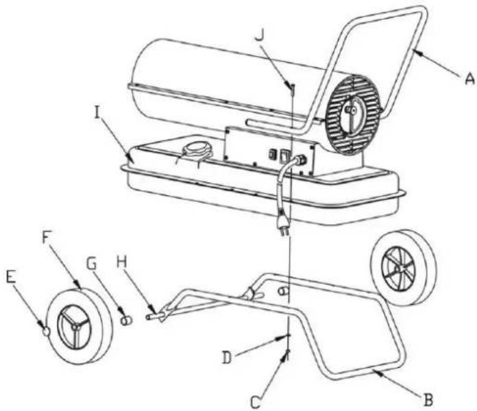
Product overview
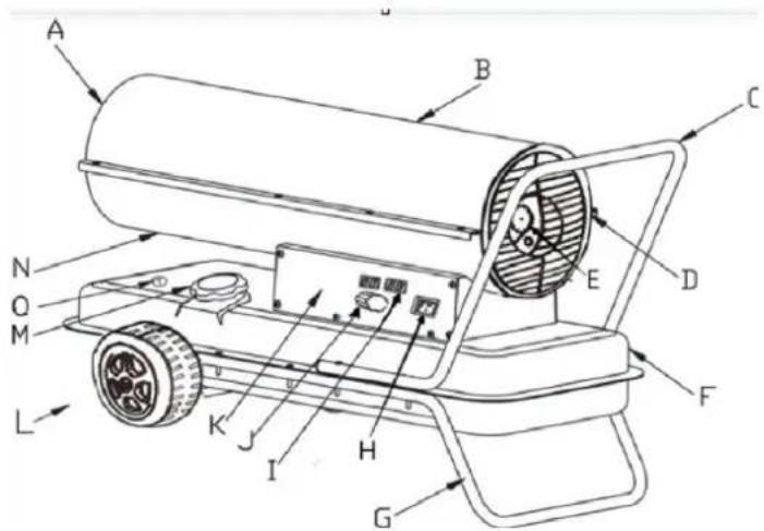
A- Hot air outlet
B- Upper shell
C- Rear handle
D- Back grill
E- Pressure gauge
F- Fuel tank
G- Lower tube frame
H- Power switch
I- Display window
J- Thermostat knob
K- Side panel
L-Wheel
M- Fuel cap
N- Lower shell
O- Fuel gauge
Installation

- Insert the wheel axle into the corresponding hole of the lower tube frame. Place bushings G at both ends of the axle, then slide the wheel F over the wheel axle H. Secure the wheel by placing the wheel cap E on the end of the axle.
- Position the product body onto the lower tube frame B, ensuring that the 4 holes in the handle frame align with the corresponding 4 holes on the lower tube frame.
- Insert screws J into the holes, place flat washers D under the lower tube frame B, and tighten the hexagonal screw C securely.
- Insert the remaining screws into the holes and tighten them using a screwdriver, following the same procedure.
Preparation before operation

NOTE
- Never use highly volatile fuels such as gasoline.
- Only refill the fuel tank when the product has stopped running and the flame has extinguished.
- Use only No. JIS1 kerosene or frost-resistant light diesel. Do not use degraded or impure kerosene or diesel.
- Ensure the fuel tank filter is installed when filling the tank.
- If kerosene or diesel comes into contact with the skin, wash immediately with soap to prevent potential skin irritation.
- The burner surface remains very hot after the flame goes out. Do not touch it or allow the oil pump to contact the burner to prevent burns or injury.
How to fill the fuel tank when empty:
- Ensure the power plug is disconnected from the power source and that the power switch is in the OFF position "0".
- Place the product on stable, level ground. Remove the fuel cap and fill the fuel tank, ensuring the fuel filter is properly installed. Do not overfill—refer to the full level position as indicated in the figure.
- Check for any water or debris in the fuel tank and clean it if necessary to ensure proper operation.
- Fill the tank with kerosene or diesel using an oil pump, ensuring the fuel filter is in place. After filling, turn the cap clockwise and tighten securely.
Fill the fuel tank (see the figure below):
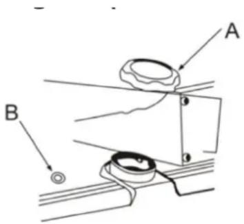
A- Fuel tank cap
B- Fuel gauge
When there is some fuel (Kerosene or Diesel) in the tank:

ATTENTIONS
- Only inspect the appliance after the flame has extinguished and the power plug has been disconnected from the power source.
- Before ignition, ensure there is no oil leakage. If oil leakage is detected, do not use the appliance and contact your dealer for assistance.
- Check the interior of the fuel tank, and if there is water or debris inside, clean the tank before further use.
Operation

WARNINGS
- Ensure the fuel tank has enough fuel before ignition.
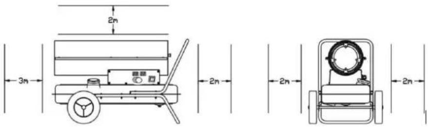
- Keep a safe distance from the heating part after ignition. Maintain a minimum distance of 3 meters in front of the hot air outlet, 2 meters above, and more than 2 meters on the left and right sides (refer to the figure below for safety distance).
- Stop using the appliance immediately if smoke or strange odors are detected.
-
Ensure the product is properly ignited before leaving it unattended.
-
Safety distance
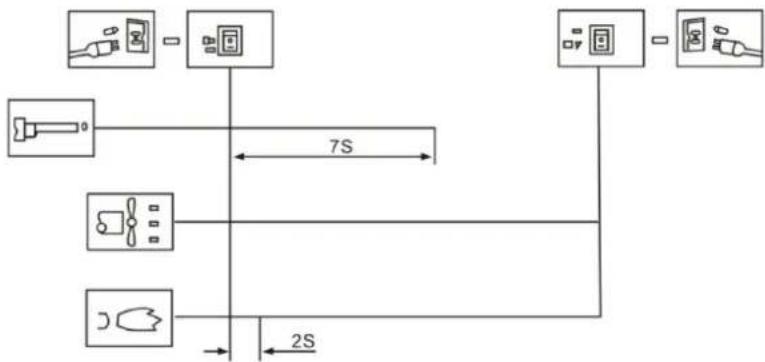
Insert the plug into the socket and set the power switch to position "1". The indicator light will turn on, and the product will ignite automatically if the set temperature is higher than the ambient temperature, as displayed on the LED digital temperature display.
If the product does not start, turn the power switch to "0" and then back to "1". If the product still fails to start after three attempts, please contact your dealer for assistance.
ATTENTION While the product is operating, ensure the floor or ground beneath it does not overheat to prevent the risk of fire.
Flame Out Procedure
-
When shutting off the product, ensure the flame is fully extinguished before leaving the appliance.
-
Set the power switch to position "0", wait for the fan to stop running, and the indicator light to go off. Then, remove the plug from the socket.
Safety Devices
- Flame-Out Protection: The product uses a photocell to monitor the flame in the burn chamber during normal operation. If the flame goes out, the photosensitive resistor's resistance will increase significantly, causing the system to cut off the Electrovalve Assembly and automatically stop the fuel supply.
- Electrical Power Breakdown Protection: In case of a power outage, the product will stop functioning without the need to unplug it. Once the power is restored, the indicator will light up, but the product will not resume operation automatically. You must press the power switch to restart the product.
Working principles
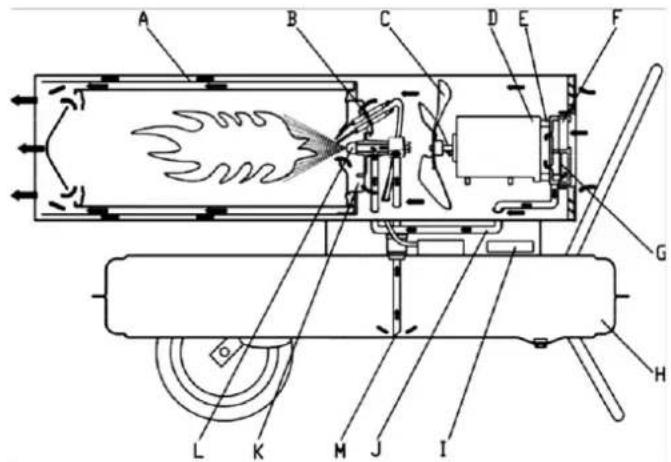
A- Combustion chamber
B- Spark plug
C- Fan blade
D- Motor
E- Pump
F- Air intake filter
G- Air output filter
H- Fuel tank
I- Controller
J- Air inlet pipe
K- Flame steady plate
L- Oil nozzle
M- Oil sucking pipe
Description of working principles:
To begin, open the fuel cap and add kerosene or diesel to the tank, then securely replace the fuel cap. Plug the power cord into the socket and turn the power switch to the "1" position. The motor will start, and the digital temperature display will light up. The left display shows the set temperature, and the right one shows the room temperature. When the set temperature exceeds the room temperature, the product will ignite automatically, and the spark plug will start the ignition process.
This product is equipped with an electric air pump, which forces air through the air line connected to the fuel intake, then through a nozzle in the burner head. As air passes the fuel intake, it draws fuel from the tank into the burner nozzle, where the fuel-air mixture is sprayed as a fine mist into the combustion chamber.
A fast-turning fan blows air into the system:
-
Air enters the flame steady plate and burner, providing additional oxygen to ensure efficient combustion, while also carrying heat from inside the burner to the outside.
-
Air passes through the heat insulation layer to prevent the burner surface from overheating by removing excess heat.
The spark plug stops working after 12 seconds once ignition is successful.
Troubleshooting
Trouble Analysis
Before sending the product for repair, please check the following common occurrences that are not actual faults:
| Problem | Reason |
| Odor, smoke, or spark emitted during first use | This is normal. Air and dust mixed in the combustion process will cause this. Wait for some time, and it will disappear. |
| Ignition issues, strange sounds, odor, or white smoke when first used or after fuel runs out | Air is mixed in the fuel line. This issue will resolve itself once the air is pushed out of the pipe. |
| Strange sounds during ignition or flame out | These noises are caused by the expansion and contraction of the product's metal parts. This is normal. |
| Fire or sparks appear at the outlet during ignition | Fuel and air from the previous use remain in the oil pipe, causing improper fuel-air mixing and non-continuous burning. Sparks may also be caused by residual carbon powder, which is normal. |
These are common conditions when using this product and do not necessarily indicate a malfunction.
Faults and Solutions
| Problem | Possible Reasons | Solution |
| Product stops working after running for a short time, "E1" displayed on the screen | Incorrect pressureInlet, outlet, or air filter cotton is dirtyDiesel filter is dirtyFuel oil nozzle is dirtyPhotocell lens is dirtyIncorrect installation of the photocellPhotocell damagedConnection issue between main PCB and photocell | Adjust the pump pressureClean or replace the air filterClean or replace the diesel filterClean or replace the fuel nozzleClean or replace the photocellAdjust the photocell positionReplace the photocellCheck all electrical connections |
| Product does not work or motor stops after a short time, "E1" displayed | Fuel exhaustedIncorrect pressureSpark plug or airlock is corrodedFuel filter is dirtyFuel nozzle is dirtyFuel tank contains moisturePCB circuit and transformer connection issueIgnition pin and transformer not connectedDefective igniter | Refill the fuel tankAdjust the pump pressureClean or replace the spark plugClean or replace the fuel filterClean or replace the nozzleRinse the tank with fresh keroseneInspect electrical connectionsConnect the ignition pin and transformerReplace the igniter |
| LED display shows "E2" | Temperature probe is damaged or has fallen off | Replace the temperature probe |
| Poor combustion / Too much smoke | Dirty air filter inlet or outletDirty fuel filterPoor fuel qualityIncorrect air pressure | Clean or replace the air filterClean or replace the fuel filterEnsure fuel is clean and freshAdjust air pressure |
| Product does not turn on and LED displays "--" | 1. Temperature sensor overheated2. PCB fuse burnout3. Temperature sensor not connected to PCB | 1. Turn off the power switch and restart after 10 minutes once the product has cooled2. Check and replace the fuse3. Check all electrical connections |
This guide provides solutions for common issues with your product, allowing you to troubleshoot before seeking professional assistance.
Maintenance

NOTE
- Always turn off the product and unplug it from the power source before performing any maintenance.
- Never perform maintenance while there is fuel in the tank.
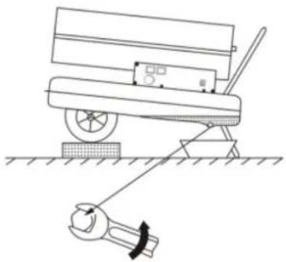
Check the fuel tank
If there is waste or water in the fuel tank, it is essential to clean and drain the tank. Follow these steps to drain the fuel tank (see the figure below for guidance):
- Place the product on a stable working surface and position an oil container beneath the fuel tank.
- Using a spanner, loosen the drain screw to release the water and waste from inside the tank.
- Once the tank is fully drained, tighten the drain screw securely and wipe away any remaining water or oil to ensure the area is clean.
natural_image
Diagram of a mechanical device with a wrench and pulley system, no text or symbols presentDrain the fuel tank
Disposing of Used Devices
Do not dispose of this device in municipal waste systems. Hand it over to an electric and electrical device recycling and collection point. Check the symbol on the product, instruction manual and packaging. The plastics used to construct the device can be recycled in accordance with their markings. By choosing to recycle you are making a significant contribution to the protection of our environment.
Contact local authorities for information on your local recycling facility.
Parts
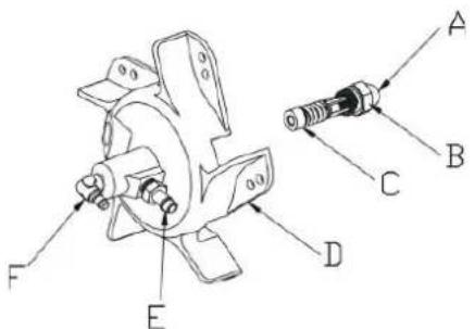
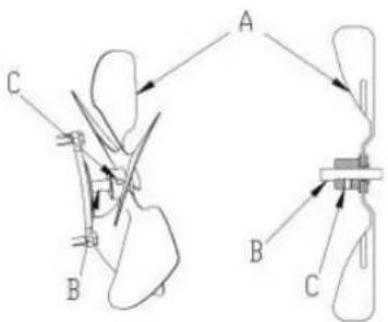
Burner head
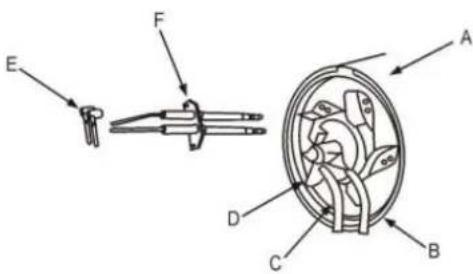
A- Burner assembly
B- Air inlet pipe
C- Oil inlet pipe
D- Flame steady plate
E- High voltage line
F- Spark plug
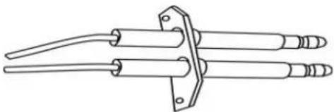
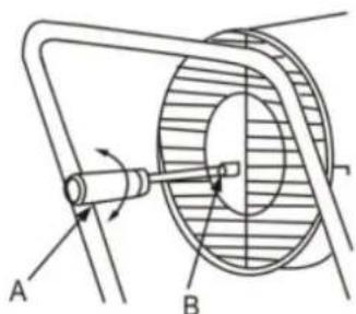
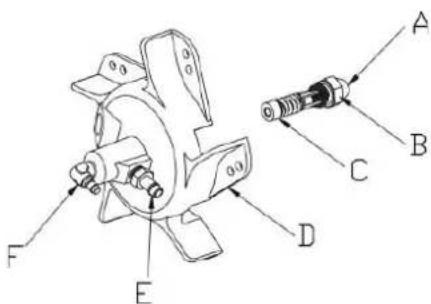
Spark plug
The distance between the electrode should be in scope of 4-5 mm, to get the best ignition result.
natural_image
Line drawing of three cylindrical mechanical components with end caps and a central bracket (no text or symbols)Gap between the electrode: 4-5mm
Assembling the oil nozzle
A- Oil nozzle
B- Nozzle core
C- Seal ring
D- Flame steady plate
E- Air pipe fitting
F- Oil pipe fitting
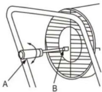
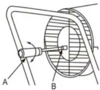
Pressure adjustment
A- Minus screw driver
B- Pressure adjustment screw
Air pump
By maintenance the air pump must be proper assembled, to prevent low air pressure or air leakage.
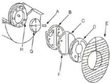
A- Pump blade
B- Pump cover
C- Air intake filter
D- Pressure cover
E- Air inlet guard
F- Air outlet filter
G- Pump core
H- Connecting part
The match between the pump body and pump core
The four pump blades are set within the four grooves of the pump core, which rotate centrifugally in a clockwise direction inside the pump. The gap between the pump enclosure and the pump core should be maintained at 0.06–0.08mm to ensure the air pump generates sufficient pressure for optimal operation.
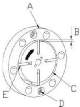
A- Pump body
B- Gap 0.06\~0.08mm
C- Pump core
D- Screw
E- Pump blade
Install the fan blade onto the motor shaft and use a set screw to tighten it securely, ensuring it is firmly fixed in place.
A- Fan blade
B- Motor shaft
C- Set screw

A- Komora spalania
B- ŚWIECA ZAPŁONOWA:
C- Łopatka wentylatora
D- Silnik
E- Pompka
natural_image
Diagram of a mechanical device with a wrench and gear, no text or symbols presentA- Zespół palnika
natural_image
Line drawing of three elongated mechanical components with a flanged base (no text or symbols)A- Dysza olejowa
B- Rdzeń dyszy
A- Łopatka pompy
B- Pokrywa pompy
A- Łopatka wentylatora
B- Wał silnika
C- Śruba ustalająca

A- Spalovací komora
B- ZAPALOVACÍ SVÍČKA:
C- Lopatka ventilátoru
D- Motor
E- Čerpadlo
natural_image
Diagram of a mechanical device with a wrench and lever, no text or symbols presentA- Sestava hořáku
natural_image
Line drawing of three elongated mechanical components with a flanged end (no text or symbols)Mezera mezi elektrodou : 4-5 mm
A- Olejová tryska
B- Jádro trysky
C- Těsnicí kroužek
A- Čepel čerpadla
B- Kryt čerpadla
natural_image
Diagram of a mechanical device with a wrench and lever, no text or symbols presentnatural_image
Line drawing of three cylindrical mechanical components with a flanged base and mounting bracket (no text or symbols)A- Buse d'huile
B- Noyau de buse
A- Lame de pompe
B- CANDELA DI ACCENSIONE:
natural_image
Simple line drawing of a mechanical device with a wrench and lever, no text or symbols presentF- CANDELA DI ACCENSIONE:
CANDELA DI ACCENSIONE:
natural_image
Line drawing of three elongated cylindrical objects with a central bracket and mounting base (no text or symbols)A- Ugello dell'olio
A- Lama della pompa
A- Salida de aire caliente
B- Cáscara superior
C- Mango trasero
D- Parrilla trasera
E- Manómetro
natural_image
Diagram of a mechanical device with a tool and spring attached to a cart (no text or symbols)natural_image
Line drawing of a three-wheeled electrical connector with leads and mounting bracket (no text or symbols)A- Boquilla de aceite
A- Cuchilla de bomba
B- Tapa de la bomba
A- Robbanótér
B- GYUJTÓGYERTYA:
C- Ventilátorlapát
D- Motor
E- Szivattyú
F- Légbeszívó szűrő
natural_image
Diagram of a mechanical device with a wrench and lever, no text or symbols presentnatural_image
Line drawing of three elongated cylindrical objects with a central bracket and mounting base (no text or symbols)A- Olajfúvóka
B- Fúvóka mag
C- Tömítőgyűrű
D- Lángálló lemez
A- Szivattyú lapát
B- Szivattyúfedél
C- Légbeszívó szűrő
D- Nyomófedél
A- Ventilátorlapát
B- Motortengely
C- Állítócsavar

Procedure for at slukke for flammen
natural_image
Diagram of a mechanical device with a wrench and lever, no text or symbols presentTøm brændstoftanken
A- Brændersamling
B- Luftindgangsrør
C- Olieindløbsrør
D- Flammebestandig plade
natural_image
Line drawing of three elongated mechanical components with a flanged end (no text or symbols)Mellemrum mellem elektroderne: 4-5mm
A- Oliedyse
B- Dysekerne
C- Tætningsring
D- Flammebestandig plade
A- Pumpeblad
B- Pumpedæksel
C- Luftindtagsfilter
D- Trykdæksel
A- Ventilatorskovl
B- Motoraksel
C- Indstillingsskrue

A- Polttokammio
B- Sytytystulppa
C- Tuulettimen terä
D- Moottori
E- Pumppu
natural_image
Diagram of a mechanical device with a wrench and lever, no text or symbols presentnatural_image
Line drawing of a mechanical tool or probe with three cylindrical components and a flanged bracket (no text or symbols)A- Öljysuutin
B- Suuttimen ydin
C- Tiivisterengas
A- Pumpun terä
B- Pumpun kansi
A- Tuulettimen terä
B- Moottorin akseli
C- Aseta ruuvi

A- Verbrandingskamer
B- Bougie
C- Ventilatorblad
D- Motor
E- Pomp
natural_image
Diagram of a mechanical device with a wrench and pulley system, no text or symbols presentA- Brander montage
B- Luchtinlaatbuis
C- Olie-inlaatbuis
natural_image
Line drawing of three cylindrical electronic components with leads and connectors (no text or symbols)A- Oliesproeier
A- Pompblad
B- Pompdeksel
A- Ventilatorblad
B- Motoras
C- Stelschroef

A- Varmluftsuttak
B- ∅vre skall
C- Bakre håndtak
D- Bakgrill
E- Trykkmåler
F- Drivstofftank
G- Nedre rørramme
H- Strømbryter
I- Visningsvindu
J- Termostatknapp
K- Sidepanel
L- Hjul
M- Drivstofflokk
N- Nedre skall
O- Drivstoffmåler
Installasjon
- Sett hjulakselen inn i det tilsvarende hullet på den nedre rørrammen. Plasser bøssinger G i begge ender av akselen, skyv deretter hjulet F over hjulakselen H. Fest hjulet ved å plassere hjuldekselet E på enden av akselen.
- Plasser produktkroppen på den nedre rørrammen B, og pass på at de 4 hullene i håndtaksrammen er på linje med de tilsvarende 4 hullene på den nedre rørrammen.
- Sett skruene J inn i hullene, plasser flate skiver D under den nedre rørrammen B, og stram sekskantskruen C godt.
- Sett de resterende skruene inn i hullene og stram dem med en skrutrekker, følg samme prosedyre.
A- Drivstofftanklokk
B- Drivstoffmåler
Flamme Out-prosedyre
A- Brennkammer
B- Tennplugg
C- Vifteblad
D- Motor
E- Pumpe
F- Luftinntaksfilter
natural_image
Diagram of a mechanical device with a wrench and lever, no text or symbols presentTøm drivstofftanken
A- Brennermontering
B- Luftinntaksrør
C- Oljeinntaksrør
D- Flammefast plate
E- Høyspent linje
F- Tennplugg
Tennplugg
natural_image
Line drawing of three elongated mechanical components with a flanged base (no text or symbols)Avstand mellom elektroden : 4-5 mm
A- Oljedyse
B- Dysekjerne
C- Tetningsring
D- Flammefast plate
E- Luftrørkobling
F- Oljerørbeslag
Trykkjustering
A- Minus skrutrekker
A- Pumpeblad
B- Pumpedeksel
C- Luftinntaksfilter
D- Trykkdeksel
E- Luftinntaksvakt
F- Luftutløpsfilter
G- Pumpekjerne
H- Koblingsdel
A- Vifteblad
B- Motoraksel
C- Stillskrue

A- Varmluftsutlopp
B- Övre skalet
C- Bakre handtag
D- Bakgrill
E- Tryckmätare
F- Bränsletank
G- Nedre rörram
H- Strömbrytare
I- Skyltfönster
J- Termostatratt
K- Sidopanel
L- Hjul
M- Bränslelock
N- Nedre skal
O- Bränslemätare
Installation

natural_image
Diagram of a mechanical device with a wrench and lever, no text or symbols presentTöm bränsletanken
A- Brännare montering
B- Luftintagsrör
C- Oljeinloppsrör
D- Flamfast platta
natural_image
Line drawing of a dual-crank electrical connector with leads and a mounting bracket (no text or symbols)Avständ mellan elektroden : 4-5 mm
A- Oljemunstycke
B- Munstyckskärna
C- Tätningsring
D- Flamfast platta
E- Luftrörskoppling
F- Oljerörskoppling
Tryckjustering
A- Pumpblad
B- Pumpkåpa
C- Luftintagsfilter
D- Trycklock
E- Luftintagsskydd
F- Luftutloppsfilter
G- Pumpkärna
H- Anslutningsdel
A- Fläktblad
B- Motoraxel
C- Ställskruv

natural_image
Diagram of a mechanical device with a wrench and gear, no text or symbols presentnatural_image
Line drawing of three cylindrical mechanical components with clamps and fittings (no text or symbols)A- Bico de óleo
B- Núcleo do bico
C- Anel de vedação
A- Lâmina da bomba
B- Tampa da bomba
A- Spal'ovacia komora
natural_image
Diagram of a mechanical device with a wrench and rotating arm, no text or symbols presentA- Montáž horáka
natural_image
Line drawing of three cylindrical mechanical components with end caps and leads (no text or symbols)Medzera medzi elektródami : 4-5 mm
Zostavenie olejovej trysky
A- Olejová tryska
B- Jadro dýzy
C- Tesniaci krúžok
D- Doska stabilná v plameňoch
A- Čepel'čerpadla
B- Kryt čerpadla
A- Lopatka ventilátora
B- Hriadel'motora
C- Nastavovacia skrutka

A- Капачка на резервоара за гориво
В- Горивомер
A- Горивна камера
В- Запалителна свещ
natural_image
Diagram of a mechanical device with a wrench and gear, no text or symbols presentnatural_image
Line drawing of three cylindrical mechanical components with flanges and a central bracket (no text or symbols)A- Маслена дюза
A- Перка на вентилатора
A- Θάλαμος καύσης
B- Μπουζί
natural_image
Diagram of a mechanical device with a wrench and gear, no text or symbols presentnatural_image
Line drawing of three cylindrical sensors with a clamp and terminal connectors (no text or symbols)Α- Ακροφύσιο λαδιού
Α- Λεπίδα αντλίας
B-Κάλυμμα αντλίας
- Umetnite osovinu kotača u odgovarajuću rupu donjeg okvira cijevi. Postavite čahure G na oba kraja osovine, zatim gurnite kotač F preko osovine kotača H. Učvrstite kotač postavljanjem poklopca kotača E na kraj osovine.
- Postavite tijelo proizvoda na donji cijevni okvir B, pazeći da su 4 rupe u okviru ručke poravnate s odgovarajuće 4 rupe na donjem cijevnom okviru.
- Umetnite vijke J u rupe, postavite ravne podloške D ispod donjeg okvira cijevi B i čvrsto zategnite šesterokutni vijak C.
- Umetnite preostale vijke u rupe i zategnite ih pomoću odvijača, slijedeći isti postupak.
A- Čep spremnika goriva
B- Mjerač goriva
A- Komora za izgaranje
B- Svjećica
C- Lopatica ventilatora
D- Motor
E- Pumpa
F- Filter za usis zraka
G- Filtar izlaza zraka
H- Spremnik goriva
I- Kontrolor
natural_image
Diagram of a mechanical device with a wrench and lever, no text or symbols presentIspraznite spremnik goriva
natural_image
Line drawing of three elongated mechanical components with no text or symbolsRazmak između elektroda : 4-5 mm
Sastavljanje mlaznice za ulje
A- Mlaznica za ulje
B- Jezgra mlaznice
C- Brtveni prsten
D- Ploča s postojanim plamenom
A- Oštrica pumpe
B- Poklopac pumpe
C- Filter za usis zraka
D- Poklopac za pritisak
E- Štitnik za ulaz zraka
A- Lopatica ventilatora
B- Osovina motora
A- Kuro bako dangtelis
B- Kuro matuoklis
A- Degimo kamera
B- Uždegimo žvakė
C- Ventiliatoriaus mentè
D- Variklis
E- Siurblys
F- Oro jsiurbimo filtras
natural_image
Diagram of a mechanical device with a tool and spring attached to a cart, no text or symbols presentA- Degiklio surinkimas
B- Oro jleidimo vamzdis
C- Alyvos jleidimo vamzdis
natural_image
Line drawing of three elongated mechanical components with no text or symbolsA- Alyvos antgalis
B- Purkštuko šerdis
A- Siurblio menté
B- Siurblio dangtis
C- Oro jsiurbimo filtras
D- Slègio dangtelis
A- Ventiliatoriaus menté
B- Variklio velenas
A- leşire aer cald
B- Înveliş superior
C- Mâner din spate
D- Gratar din spate
E- Manometru
F- Rezervor de combustibil
A- Camera de ardere
B- Bujie
natural_image
Diagram of a mechanical device with a wrench and gear, no text or symbols presentnatural_image
Line drawing of a three-pronged electrical fuse with leads and terminal connectors (no text or symbols)A- Duza de ulei
B- MiezuI duzei
C- Inel de etanşare
D- Farfurie stabilă
A- Lama pompei
B- Capacul pompei
C- Filtru de admisie aer
A- Pokrov rezervoarja za gorivo
B- Merilnik goriva
Ko je v rezervoarju nekaj goriva (kerozin ali dizel):

POZOR
A- Zgorevalna komora
B- Vžigalna svečka
C- Rezilo ventilatorja
D- Motor
E- Črpalka
F- Filter za dovod zraka
natural_image
Diagram of a mechanical device with a wrench and lever, no text or symbols presentIzpraznite rezervoar za gorivo
Odstranjevanje rabljenih naprav
A- Montaža gorilnika
natural_image
Line drawing of a three-crank electrical tool with no text or symbolsRazmak med elektrodama : 4-5 mm
A- Oljna šoba
B- Jedro šobe
C- Tesnilni obroč
A- Rezilo črpalke
B- Pokrov črpalke
C- Filter za dovod zraka
D- Tlačni pokrov
A- Rezilo ventilatorja
B- Motorna gred
C- Nastavitveni vijak
For the disposal of the device please consider and act according to the national and local rules and regulations.
CONTACT
expondo Polska sp. z o.o. sp. k.