TP-MA 36/30 Li BL - Plane EINHELL - Free user manual and instructions
Find the device manual for free TP-MA 36/30 Li BL EINHELL in PDF.

| Product Type | Cordless wall groove cutter (router) |
| Brand | Einhell |
| Model | TP-MA 36/30 Li BL |
| Power supply | Li-Ion battery 36 V (Power-X-Change series, not included) |
| No-load speed | 5400 rpm |
| Groove depth | 5 to 30 mm |
| Groove width | 8 to 30 mm |
| Max. wheel diameter | 125 mm |
| Bore | 22.2 mm |
| Spindle thread | M8 |
| Weight | 4.25 kg |
| Sound pressure level (LpA) | 90 dB(A) (uncertainty 3 dB) |
| Sound power level (LWA) | 101 dB(A) (uncertainty 3 dB) |
| Vibration (ah) | 8.46 m/s² (uncertainty 1.5 m/s²) |
| Delivery contents | 2 diamond cutting wheels, flange nut wrench, operating instructions, safety instructions |
| Depth adjustment | Via depth stop (fixing screw) |
| Groove width adjustment | Adding or removing spacer washers (max 6) |
| Dust extraction connection | Yes, adapter for vacuum cleaner |
| Spindle lock | Yes, for wheel change |
| Safety switch | Start lock |
| Overload protection | Automatic motor shut-off in case of excessive load |
| Use | Grooving in masonry (not reinforced concrete, asbestos prohibited) |
| Maintenance and cleaning | Clean with a damp cloth and a little soap; do not let water enter |
| Spare parts | Available at www.Einhell-Service.com |
| Warranty | 2 years (conditions: non-professional use, manufacturing defect) |
Frequently Asked Questions - TP-MA 36/30 Li BL EINHELL
User questions about TP-MA 36/30 Li BL EINHELL
0 question about this device. Answer the ones you know or ask your own.
Ask a new question about this device
Download the instructions for your Plane in PDF format for free! Find your manual TP-MA 36/30 Li BL - EINHELL and take your electronic device back in hand. On this page are published all the documents necessary for the use of your device. TP-MA 36/30 Li BL by EINHELL.
USER MANUAL TP-MA 36/30 Li BL EINHELL
When using the equipment, a few safety precautions must be observed to avoid injuries and damage. Please read the complete operating instructions and safety regulations with due care. Keep this manual in a safe place, so that the information is available at all times. If you give the equipment to any other person, hand over these operating instructions and safety regulations as well. We cannot accept any liability for damage or accidents which arise due to a failure to follow these instructions and the safety instructions.
Explanation of the symbols used (see Fig. 13)
- Danger! - Read the operating instructions to reduce the risk of injury.
- Caution! Wear ear-muffs. The impact of noise can cause damage to hearing.
- Caution! Wear a breathing mask. Dust which is injurious to health can be generated when working on wood and other materials. Never use the device to work on any materials containing asbestos!
- Caution! Wear safety goggles. Sparks generated during working or splinters, chips and dust emitted by the device can cause loss of sight.
1. Safety regulations
The corresponding safety information can be found in the enclosed booklet.
Danger!
Read all safety regulations and instructions.
Any errors made in following the safety regulations and instructions may result in an electric shock, fire and/or serious injury.
Keep all safety regulations and instructions in a safe place for future use.
2. Layout and items supplied
2.1 Layout (Fig. 1/2)
- Handle
- Spindle lock
- Guard hood
- Operating switch
- Safety lock-off
- Locking screw for depth stop
- Depth stop
- Additional handle
-
Connection for dust extractor
-
Guide roller
-
Screw for flange cover
- Flange cover
- Hex key
2.2 Items supplied
Please check that the article is complete as specified in the scope of delivery. If parts are missing, please contact our service center or the sales outlet where you made your purchase at the latest within 5 working days after purchasing the product and upon presentation of a valid bill of purchase. Also, refer to the warranty table in the service information at the end of the operating instructions.
- Open the packaging and take out the equipment with care.
- Remove the packaging material and any packaging and/or transportation braces (if available).
Check to see if all items are supplied. - Inspect the equipment and accessories for transport damage.
If possible, please keep the packaging until the end of the guarantee period.
Danger!
The equipment and packaging material are not toys. Do not let children play with plastic bags, foils or small parts. There is a danger of swallowing or suffocating!
Cutting wheel (2x)
- Flange nut wrench
Original operating instructions
- Safetyinstructions
3. Proper use
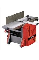
This equipment is designed for cutting channels for pipes and cables in masonry walls.
This equipment is not suitable for making cuts in reinforced concrete.
The equipment is to be used only for its prescribed purpose. Any other use is deemed to be a case of misuse. The user / operator and not the manufacturer will be liable for any damage or injuries of any kind caused as a result of this.
GB
4. Technical data
Motor power supply: 36 V DC
Rated speed: .5400 min-1
Max. wheel diameter (rated capacity): ... 125 mm
Mounting hole: 22.2 mm
Channel depth: 5-30 mm
Channel width: 8-30 mm
Mounting spindle thread: M8
Weight: 4.25 kg
Important!
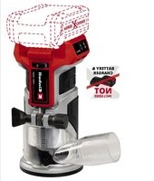
The equipment is supplied without rechargeable batteries and without a charger and is allowed to be used only with the lithium-ion batteries of the Power X-Change series!
The lithium-ion batteries of the Power X-Change series are allowed to be charged only with PowerX chargers.
Danger!
Sound and vibration
Sound and vibration values were measured in accordance with EN 60745.
L_pA sound pressure level 90 dB(A)
K_pA uncertainty 3 dB
LWA sound power level 101 dB(A)
K_WA uncertainty 3 dB
Wear ear-muff s.
The impact of noise can cause damage to hearing.
Total vibration values (vector sum of three directions) determined in accordance with EN 60745.
Vibration emission value a_h = 8.46 m/s^2 K uncertainty = 1.5 m/s²
The specific vibration value was established in accordance with a standardized testing method. It may change according to how the electric equipment is used and may exceed the specific value in exceptional circumstances.
The specified vibration value can be used to compare the equipment with other electric power tools.
The specified vibration value can be used for initial assessment of a harmful effect.
Keep the noise emissions and vibrations to a minimum.
Only use appliances which are in perfect working order.
Service and clean the appliance regularly.
Adapt your working style to suit the appliance.
Do not overload the appliance.
- Have the appliance serviced whenever necessary.
- Switch the appliance off when it is not in use.
Caution!
Residual risks
Even if you use this electric power tool in accordance with instructions, certain residual risks cannot be rules out. The following hazards may arise in connection with the equipment's construction and layout:
- Lung damage if no suitable protective dust mask is used.
- Damage to hearing if no suitable ear protection is used.
- Health damage caused by hand-arm vibrations if the equipment is used over a prolonged period or is not properly guided and maintained.
5. Before starting the equipment
Warning!
Always remove the battery pack before making adjustments to the equipment.
5.1 Setting the groove depth (Fig. 8)
Slacken the locking screw (6).
- Set the depth stop (7) to the desired depth.
- Tighten the locking screw (6).
5.2 Fitting the dust extractor adapter (Fig. 3)
Caution! For health and safety reasons it is imperative that you use a dust extractor. The extractor socket is suitable for use on vacuum extractor units (vacuum cleaners). The extractor unit must be suitable for the extraction of fine dust.
Connect a suitable vacuum cleaner, as shown in
Fig. 3, to the dust extraction connector.
GB
5.3 Trial run for new diamond cutting wheels Have the equipment run in idle mode for at least 1 minute with the cutting wheels fitted. Replace vibrating wheels immediately.
6. Operation
6.1 Charging the Li battery pack (Fig. 4-5)
-
Remove the battery pack (b) from the handle, pressing the pushlock button (c) downwards to do so.
-
Check that your mains voltage is the same as that marked on the rating plate of the battery charger. Insert the power plug of the charger (d) into the mains socket outlet. The green LED will then begin to flash.
-
Push the battery pack onto the battery charger.
In section 10 (Charger indicator) you will find a table with an explanation of the LED indicator on the charger.
If the battery pack fails to charge, check for the following:
- voltage at the power socket
whether there is good contact at the charging contacts of the charging unit
If the battery pack still fails to charge, send
the charger and charging adapter
and the battery pack
to our customer service center.
To ensure that items are properly packaged and delivered when you send them to us, please contact our customer service or the point of sale at which the equipment was purchased.
When shipping or disposing of batteries and cordless tools, always ensure that they are packed individually in plastic bags to prevent short circuits and fi res.
To ensure that the battery pack provides long service, you should take care to recharge it promptly. You must recharge the battery pack when you notice that the performance of the device drops. Never allow the battery pack to become fully discharged. This will cause it to develop a defect.
6.2 Battery capacity indicator (Fig. 6)
Press the battery capacity indicator switch (f). The battery capacity indicator (e) shows the charge status of the battery using 3 LEDs.
All 3 LEDs are lit:
The battery is fully charged.
2 or 1 LED(s) are lit:
The battery has an adequate remaining charge.
1 LED fil ashes:
The battery is empty, recharge the battery.
All LEDs blink:
The battery temperature is too low. Remove the battery from the equipment, keep it at room temperature for one day. If the fault reoccurs, this means that the rechargeable battery has undergone exhaustive discharge and is defective. Remove the battery from the equipment. Never use or charge a defective battery.
6.3 Switch (Fig. 7)
The equipment comes with a safety switch which is designed to prevent accidents.
To start the equipment, push the locking lever (5) forwards and then press the On/Off switch (4).
Warning! Wait until the machine has reached its top speed.
6.4 Changing and setting the diamond cutting wheels (Fig. 8-11)
Warning!
Always remove the battery pack before making adjustments to the equipment.
Removing:
- Undo the locking screw for the depth stop (6) and remove (Fig. 8)
Swing the depth stop (7) downwards (Fig. 9) - Slacken the screw for the flange cover (11) and open the flange cover (12) (Fig. 9)
- Press and hold the spindle lock (2) and undo the socket head screw (h) with the supplied hex key (13) (Fig. 10)
-
Remove the following as shown in Fig. 11:
-
the outer flange (a)
- the top cutting wheel (b)
- the top inner flange (c)
-6x spacers (d) - the bottom cutting wheel (e)
- the bottom inner flange (f)
GB
Important! Thoroughly clean all the spacers and flanges.
Fitting:
Important! Diamond cutting wheels must always be replaced as pairs!
- Fit the bottom inner flange (f) and the bottom cutting wheel (e)
- Important! Check the direction of rotation of the cutting wheel!
- Fit the number of spacers (d) required for the groove width
- Place the top inner flange (c) – with its raised side up – onto the last fitted spacer. Important! Each spacer is approx. 3.5mm wide. The groove width results from the number of spacers (d), the top inner flange (c) between the cutting wheels, and the thickness of the two cutting wheels
- Put on the top cutting wheel (b)
Important! Check the direction of rotation of the cutting wheel! - Fit any spacers (d) that might still be left over, reattach the outer flange (a), and screw the socket head screw (h) back in place.
Warning! All 6 spacers (d) must be fitted irrespective of the desired groove width!
Close and fasten the flange cover (12) and swivel the depth stop (7) back in place.
Fasten the depth stop (7) using the locking screw for depth screw (6).
Important! Check that all the parts are seated firmly and correctly.
Caution:
Only ever press the spindle lock when the motor and grinding spindle are at a standstill! The spindle lock must be kept pressed while the wheel is being changed!
6.5 Motor
It is vital for the motor to be well ventilated during operation. Be sure, therefore, to keep the ventilation holes clean at all times.
6.6 Working with the masonry channel cutter (Fig. 12)
The device is fitted with an overload cut-out. The motor will cut out if overloaded. Relieve the load on the motor immediately and allow the masonry channel cutter to cool down for approx. 1 minute without load.
Danger! The device is suitable for dry cutting only!
Use a cable/pipe detector to check for concealed electric cables and gas and water pipes in the wall before you start using the masonry channel cutter.
- Select the desired groove width (see 6.4) and groove depth (see 5.1).
Only ever guide the device along the workpiece while switched on.
- Place the device against the wall with the roller (10) against the wall.
- Switch on the device and then cut slowly into the wall until the stop (7) rests against the wall.
Now you can cut the groove in the wall. Take care with the cutting direction (a) as you do so. The device must always be handled on a counterrotating basis otherwise there is a risk that it may be forced out of the cut in an uncontrolled manner.
Caution! Cut in a straight line only. It is not possible to cut curves.
At the end of the groove, swing the device out of the groove before you switch it off.
- You can then cut out the ridge between the two grooves with a chisel.
Important! It is prohibited to use this equipment on materials containing asbestos!
GB
7. Cleaning, maintenance and ordering of spare parts
Danger!
Always pull out the battery pack before starting any cleaning work.
9. Storage
Store the equipment and accessories in a dark and dry place at above freezing temperature. The ideal storage temperature is between 5 and 30^ . Store the electric tool in its original packaging.
7.1 Cleaning
- Keep all safety devices, air vents and the motor housing free of dirt and dust as far as possible. Wipe the equipment with a clean cloth or blow it with compressed air at low pressure.
We recommend that you clean the device immediately each time you have finished using it.
Clean the equipment regularly with a moist cloth and some soft soap. Do not use cleaning agents or solvents; these could attack the plastic parts of the equipment. Ensure that no water can seep into the device. The ingress of water into an electric tool increases the risk of an electric shock.
7.2 Maintenance
There are no parts inside the equipment which require additional maintenance.
7.3 Ordering replacement parts:
Please quote the following data when ordering replacement parts:
Type of machine
Article number of the machine
Identification number of the machine
- Replacement part number of the part required For our latest prices and information please go to www.Einhell-Service.com
8. Disposal and recycling
The equipment is supplied in packaging to prevent it from being damaged in transit. The raw materials in this packaging can be reused or recycled. The equipment and its accessories are made of various types of material, such as metal and plastic. Never place defective equipment in your household refuse. The equipment should be taken to a suitable collection center for proper disposal. If you do not know the whereabouts of such a collection point, you should ask in your local council offices.
10. Charger indicator
| Indicator status Explanations and actions | ||
| Red LED Green LED | ||
| Off | Flashing | Ready for use The charger is connected to the mains and is ready for use; there is no battery pack in the charger |
| On Off Charging | The charger is charging the battery pack in quick charge mode. The charging times are shown directly on the charger. Important! The actual charging times may vary slightly from the stated charging times depending on the existing battery charge. | |
| Off | On | The battery is charged and ready for use. (READY TO GO) The unit then changes over to gentle charging mode until the battery is fully charged. To do this, leave the rechargeable battery on the charger for approx. 15 minutes longer. Action: Take the battery pack out of the charger. Disconnect the charger from the mains supply. |
| Flashing Off | Adapted charging | |
| The charger is in gentle charging mode. For safety reasons the charging is performed less quickly and takes more time. The reasons can be: - The rechargeable battery has not been used for a very long time. - The battery temperature is outside the ideal range. Action: Wait for the charging to be completed; you can still continue to charge the battery pack. | ||
| Flashing Flashing Fault | Charging is no longer possible. The battery pack is defective. Action: Never charge a defective battery pack. Take the battery pack out of the charger. | |
| On On Temperature fault | The battery pack is too hot (e.g. due to direct sunshine) or too cold (below 0°C). Action: Remove the battery pack and keep it at room temperature (approx. 20°C) for one day. | |
GB
Disposal

Power tools, rechargeable batteries, accessories and packaging should be sorted for environmental-friendly recycling.
Do not dispose of power tools and batteries/rechargeable batteries into household waste!
Only for EU countries:
According to the Directive 2012/19/EU on waste electrical and electronic equipment and its transposition into national law, power tools that are no longer usable, and, according to the Directive 2006/66/EC, defective or drained batteries must be collected separately and disposed of in an environmentally correct manner.
If disposed incorrectly, waste electrical and electronic equipment may have harmful effects on the environment and human health, due to the potential presence of hazardous substances.
Only for United Kingdom:
According to The Waste Electrical and Electronic Equipment Regulations 2013 (SI 2013/3113) (as amended) and the Waste Batteries and Accumulators Regulations 2009 (SI 2009/890) (as amended), products that are no longer usable must be collected separately and disposed of in an environmentally friendly manner.
The reprinting or reproduction by any other means, in whole or in part, of documentation and papers accompanying products is permitted only with the express consent of the Einhell Germany AG.
Subject to technical changes.
GB
Service information
We have competent service partners in all countries named on the guarantee certificate whose contact details can also be found on the guarantee certificate. These partners will help you with all service requests such as repairs, spare and wearing part orders or the purchase of consumables.
Please note that the following parts of this product are subject to normal or natural wear and that the following parts are therefore also required for use as consumables.
| Category Example | |
| Wear parts* Carbon brushes, Battery | |
| Consumables* Cutting wheels | |
| Missing parts |
- Not necessarily included in the scope of delivery!
In the effect of defects or faults, please register the problem on the internet at www.Einhell-Service.com. Please ensure that you provide a precise description of the problem and answer the following questions in all cases:
Did the equipment work at all or was it defective from the beginning?
Did you notice anything (symptom or defect) prior to the failure?
What malfunction does the equipment have in your opinion (main symptom)?
Describe this malfunction.
GB
Warranty certificate
Dear Customer,
All of our products undergo strict quality checks to ensure that they reach you in perfect condition. In the unlikely event that this equipment develops a fault, please contact our service department at the address shown on this guarantee card. You can also contact us by telephone using the service number shown. Please note the following terms under which guarantee claims can be made:
-
These guarantee terms apply solely to consumers, i.e. natural persons, who do not want to use this product in connection with either their commercial or other self-employed activities. These guarantee terms regulate additional guarantee services which the undermentioned manufacturer promises to buyers of its new products in addition to their statutory rights of guarantee. Your statutory rights of guarantee are not affected by this guarantee. Our guarantee is free of charge to you.
-
The guarantee services cover only defects due to material or manufacturing faults on the new product which you have bought in the European Union from the undermentioned manufacturer and are limited to either the rectification of said defects or the replacement of the product, whichever we prefer. Please note that only equipment under the brand name "Professional" has been designed for use in commercial, trade or professional applications. For all other products the guarantee is invalidated if the equipment is used within the guarantee period in commercial, trade or industrial applications or for other equivalent activities.
-
Our guarantee does not cover:
-
Damage to the equipment caused by failure to comply with the installation/assembly instructions or by unprofessional installation; damage caused by failure to comply with the operating instructions (e.g. connection to the wrong mains voltage or current type); damage caused by failure to comply with the maintenance and safety regulations; damage caused by exposing the equipment to abnormal environmental conditions; damage resulting from poor care and maintenance.
- Damage to the equipment caused by misuse or incorrect applications (e.g. overloading the equipment or using non-approved attachments or accessories); damage caused by foreign bodies (e.g. sand, stones, dust, ...) getting inside the equipment. Damage in transit; damage caused by force or external influences (e.g. by dropping the equipment).
-
Damage to the equipment or parts of the equipment which is owed to use-related, normal or otherwise natural wear. For example, batteries and battery packs are manufactured with a cycle limit for design-related reasons. Wear is negatively influenced in particular by load demands and charging speeds as well as exposure to heat, cold, vibration and impact.
-
The guarantee is valid for a period of 2 years starting from the purchase date of the equipment. Guarantee claims must be submitted before the end of the guarantee period and within two weeks of the defect being noticed. No guarantee claims will be accepted after the end of the guarantee period. The original guarantee period remains applicable to the equipment even if repairs are carried out or parts are replaced. In such cases, the work performed or parts fitted will not result in an extension of the guarantee period, and no new guarantee will become active for the work performed or for any replacement parts fitted. This also applies if on-site service is used.
- To assert your guarantee claim, register the defective equipment at: www.Einhell-Service.com. You will need to provide proof of purchase of the new item of equipment. Equipment returned without such proof or without a rating plate are excluded from the guarantee services because of the lack of traceability. If the defect is covered by our guarantee, then either the item in question will be repaired immediately and returned to you or we will send you a new replacement.
- If you have taken the equipment with you to a different EU country than where you bought it, we will arrange for a local service partner to provide the guarantee services. If you take the equipment outside the EU, the guarantee will not apply.
Of course, we are also happy to offer a chargeable repair service for any defects which are not covered or no longer covered by the scope of this guarantee. To take advantage of this service, please send the equipment to our service address. We draw attention to the restrictions of this guarantee concerning wear parts, consumables and missing parts as presented in the service information included in this operating manual.
Warrantor/Service:
Einhell UK Ltd, Unit 10, 1st Floor, Champion's Business Park, Arrowe Brook Road, Upton, Wirral, CH49 0AB
F
Danger!
A DEPOSSE D. 5000000000000000000000000000000000000000000000000000000000
Chere cliente, cher client.
Voeding motor: 36 V DC
Svetita 2 ali 1 lucka LED
Stimata clienta, stimate client,
produsele noastre sunt supuse unui control de calitate riguros. Daca totusi vreodata acest aparat nu va functiona irreprosabil, ne pare foarte rau si va rugam sa va adresa t centrului nosru service, la adresa indicata la finalul acestui certificat de garantie. Bineinteles ca va stam si la Telefon cu placere la dispositione, la numarul de service mentionat. Penu revendicarea pretentiilor de garantie trebuie tinut cont de urmatoarele:
Evnpwon yia to epbic
Soone sugavirus: 5-30 mm
Soone laius: 8-30 mm
Kinnitusspindi keere: M8
Kaal: 4,25 kg
Tähelepanu!
Subject to change without notice
Archive-File/Record: NAPR024440
Documents registrar: Christoph Egginger
Wiesenweg 22, D-94405 Landau/Isar
*Gg Corless masony channel cutter - P Rainurese murale sans il . I Scalatatora a bacteria - DKN Aknu-murmertress - S Baterdritten mursparfis - Cz Akumultorova drzakovici rskza de zidva - SK Akumultorata drzakovica freza de muriva - NLC Akcu-murfurres - F Resadora ranuracora inalambra - FIV Akku-mururiayrnn-sin - SLO Akumul- roskalin kizdin ulurov - H Akkus-fahormaroyo - RO Magmes de frezuturi in zidriae cu acumulator - GR PfEgeauonotiyuog, uze protropio - P Faderstorae do ropos sem lo - HRSH Akumulorata glaciala za utore u zu 162Baterjika glaciala za kanele u zu 163Pru Zbodnica zasilana akumulorotem - T R Aku duvar kanai frezels - RUS Akymythorptnur tnpoboe - EE Akuga seinaloklu - VL Akumulortine gopfretbe konatam - L7 Akumulortine muro groveli freza - BG Akymythoropthe phesta an kainanen bstenck - UOKR Akymythorptnir npoboe - MK Akymythoroptka phesta ana juneboan ha nuc

Declaration of conformity
We, Einhell UK Ltd
Champions Business Park, First Floor Unit 10, Arrowe Brook Rd, Upton, Wirral CH49 0AB, United Kingdom
declare the conformity to UK standards and legislation was assessed for:
Cordless masonry channel cutter TP-MA 36/30 Li BL (Einhell)
UK legislation
Simple Pressure Vessels (Safety) Regulation
Electrical Equipment (Safety) Regulation
Radio Equipment Regulation
Personal Protective Equipment Regulation
The Ecodesign for Energy-Related Products and Energy Information Regulation
The Restriction of the Use of Certain Hazardous Substances in Electrical and Electronic Equipment Regulation
Nolse Emisslon in the Environment by Equipment for use Outdoors Regulation
Annex V
Annex VI
Noise:measuredL ww = dB (A);guaranteed Lw = dB A
P = kW; L/0 = cm
UK Approved Body:
Supply of Machinery (Safety) Regulation
Annex IV
UK Approved Body:
UKTE Certificat No.:
Standards: BS EN 60745-1; BS EN 60745-2-22; BS EN 55014-1; BS EN 55014-2
Tom Chambers, Managing Director Einhall UK Ltd
Wirral, 2024.01.26
Archive-File/Record: NAPR024440
Article Number: 43.508.00 I-No.:21013
Subject to change without notice Wiesenweg 22, 94405 Landau/Isar, Germany
Documents registrar: Christoph Egginger
EH 05/2024 (02)