PLO-375 - Cutting plotter MSW - Free user manual and instructions
Find the device manual for free PLO-375 MSW in PDF.

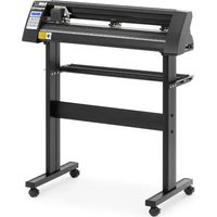
| Product type | Cutting plotter |
| Model | MSW PLO-375 |
| Dimensions (L x W x H) | 530 x 235 x 210 mm |
| Weight | ~6.45 kg |
| Rated voltage / frequency | 230 V ~ 50 Hz |
| Rated power | 90 W |
| Current | 2 A |
| Protection class | I |
| Cutting speed | 0.8 m/s |
| Cutting width | 285 mm |
| Feed width | 375 mm |
| Cutting pressure | 20 - 500 g |
| Max. cutting thickness | ≤ 1 mm |
| Repeatability | 0.1 mm |
| Connection interface | USB, COM |
| Compatible materials | Vinyl, flock, glitter, reflective materials |
| Blade replacement | Every 6 months or more often depending on use |
| Features | Reset, offline mode, speed and force adjustment, test cut |
| Included software | SignMaster (on USB key) |
| Operating temperature | 10 - 35 °C |
Frequently Asked Questions - PLO-375 MSW
User questions about PLO-375 MSW
0 question about this device. Answer the ones you know or ask your own.
Ask a new question about this device
Download the instructions for your Cutting plotter in PDF format for free! Find your manual PLO-375 - MSW and take your electronic device back in hand. On this page are published all the documents necessary for the use of your device. PLO-375 by MSW.
USER MANUAL PLO-375 MSW
KLINGENMONTAGE
natural_image
Cross-sectional diagram of a mechanical component with internal structure and labeled X (no text or symbols beyond label)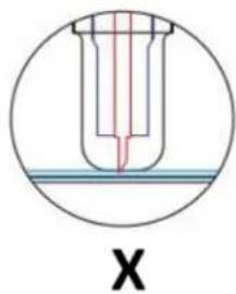
natural_image
Technical line drawing of a mechanical component with a circular vent and mounting bracket (no text or symbols)natural_image
Technical line drawing of a mechanical device with a perforated panel and cylindrical components (no text or symbols)natural_image
Technical line drawing of a mechanical component with a perforated base and mounting bracket (no text or symbols)natural_image
Line drawing of a handheld device with a circular button and directional arrows (no text or symbols)natural_image
Line drawing of a mechanical spring assembly with an arrow indicating direction (no text or symbols)natural_image
Line drawing of a portable electric shaver with a coiled cable (no text or symbols)natural_image
Technical line drawing of a mechanical assembly with no visible text or symbolsnatural_image
Technical line drawing of a mechanical component with no visible text or symbols
natural_image
Abstract geometric shape with four arrows pointing inward, no text or symbols present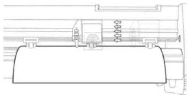
natural_image
Technical line drawing of a mechanical assembly with springs and housing (no text or symbols)This User Manual has been translated for your convenience using machine translation. Reasonable efforts have been made to provide an accurate translation; however, no automated translation is perfect nor is it intended to replace human translators. The official User Manual is the English version. Any discrepancies or differences created in the translation are not binding and have no legal effect for compliance or enforcement purposes. If any questions arise related to the accuracy of the information contained in the User Manual, please refer to the English version of those contents which is the official version.
TECHNICAL DATA
| Parameter description Parameter value | |||
| Product name | Cutting plotter | ||
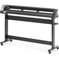
| Model | MSW-PLO-375 | MSW-PLO-1350 | MSW-PLO-720 |
| Rated voltage [V~] / frequency [Hz] | 230 / 50 | ||
| Rated power [W] | 90 | 95 | 95 |
| Current [A] | 2 | ||
| Protection class | I | ||
| Dimensions [width x depth x height; mm] | 530 x 235 x 210 | 1510 x 455 x 1000 | 880 x 450 x 1000 |
| Weight [kg] | ~6.45 | ~19 | ~15.4 |
| Cutting speed [m/s] | 0.8 | ||
| Cutting width [mm] | 285 | 1260 | 630 |
| Feeder width [mm] | 375 | 1350 | 720 |
| Cutting pressure [g] | 20-500 | ||
| Cutting thickness [mm] | ≤1 | ||
| Repeatability [mm] | 0.1 | ||
| Connection interface | USB, COM | ||
PRECAUTIONS
a) Protective material must be removed before turning on the cutting plotter.
b) Check the label on the back side of the plotter to confirm that the rated voltage required by the plotter matches the voltage of the power base.
c) Firstly make sure that the power switch is off, then plug the power supply into grounded power outlet.
d) Please do not touch the power cord with wet hands to avoid electric shock.
e) Please only use the power cord, data cable provided with this product, or manufacturer-approved replacements.
f) Please do not drop metal objects and liquids into the machine to avoid malfunction.
g) After shutting down, you must wait another 5 seconds to turn on the cutting plotter again, otherwise it will cause damage to the cutting plotter.
h) In thunderstorms, turn the power switch to OFF and unplug the power cord.
i) Please do not privately change the manufacturer's components.
j) Manufacturer reserves the right to change product specifications without prior notice.
k) The manufacturer only bears the legal obligations of the product itself sold to the users, and does not bear other losses caused by the malfunction of the products.
I) Without our company's permit, no part of this manual can be copied or transmitted in any name.
m) Do NOT drag the carriage by hand.
n) If there is an abnormal sound after powering on the machine, please turn off the power immediately and contact the after-sales department for feedback.
PRODUCT DESCRIPTION
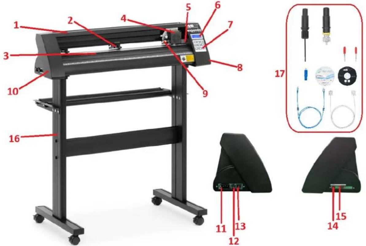
- Rail guide cover
- Pinch roller kit
- Feeding paper roller
- Carriage
- Reset switch
- Display
- Control panel
- Right side cover
- Blade clamp
- Left side cover
- Power connection socket
- Fuse holder
- Power switch
- USB port
- COM port
- Stand
- Accessories
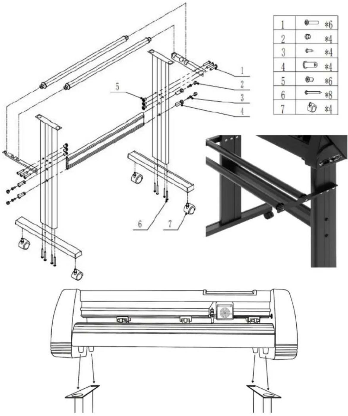
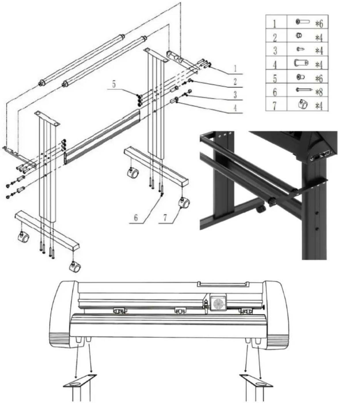
STAND ASSEMBLY

| 1 | *6 | |
| 2 | *4 | |
| 3 | *4 | |
| 4 | *4 | |
| 5 | *6 | |
| 6 | *8 | |
| 7 | *4 |
BLADE ASSEMBLY
| 1. Unscrew the cap from the blade carriage. | 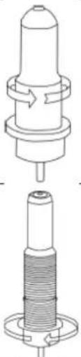 | ||
| 2. Set the brass ring on blade carriage to the fully down position. | |||
| 3. Remove the protective cover from a new blade. | [WSBT] | ||
| 4. Insert the blade into the top of the blade carriage. | 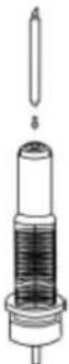 | ||
| 5. Screw the cap back onto the blade carriage. | 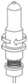 | ||
| 6. Adjust the carriage cap until the blade is protruding approximately 0.4 mm. | 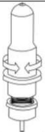 | ||
- Adjust the brass ring until it fits snug against the cap. This will help keep the cap in place during operation.
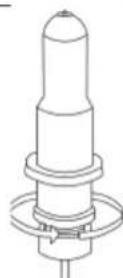
NOTE: Blades should be replaced every 6 months. They might need to be replaced more often if cutting thicker material such as flock, glitter or reflective materials.
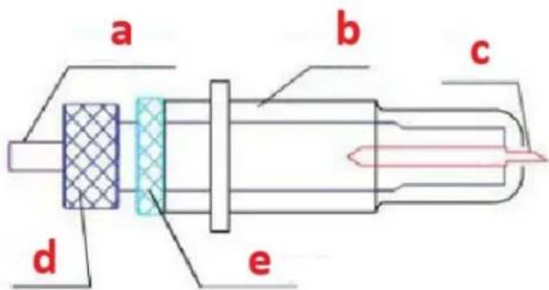
FIXING THE BLADE INTO THE HOLDER
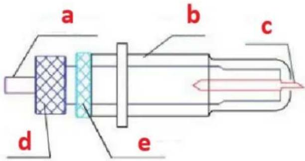
a) Pressing rod
b) Blade cover
c) Blade
d) Shank
e) Blade adjustment nut
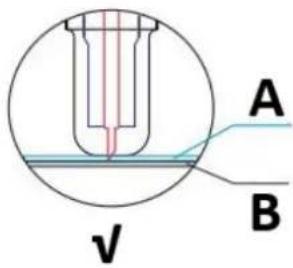
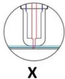
- Loosen the blade adjustment nut and rotate the shank to adjust the length of the exposed blade tip. Determine the tip length according to the thickness of the material:
natural_image
Cross-sectional diagram of a mechanical component with internal structure and labeled X (no text or symbols beyond label)
natural_image
Cross-sectional diagram of a test tube with red liquid and blue cap, labeled 'X' (no text or symbols within the diagram itself)A) Material thickness
B) Base thickness
V) Correct cutting depth
X) Left - blade tip too long; Right - blade tip too short
-
Press the pressing rod when you want to change blade. Take out the blade when it is exposed.
-
NOTE: The blade tip is very sharp – do not touch it with the finger due to possible injury and blade blunting risk!
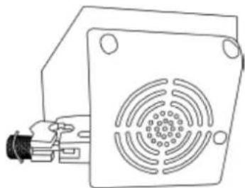
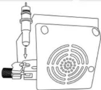
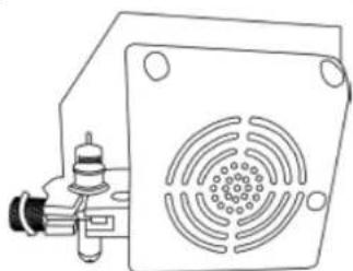
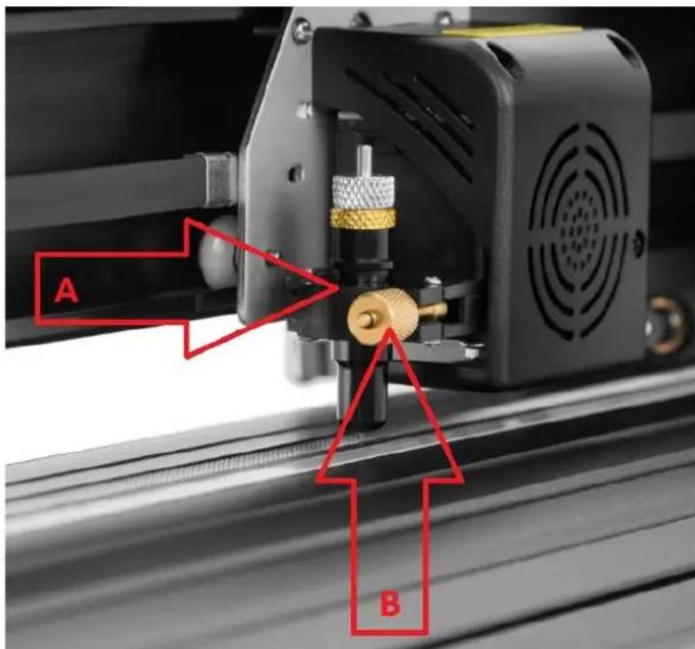
INSTALLING THE BLADE HOLDER IN THE CARRIAGE

A) Carriage slot (holds the blade assembly in carriage arm)
B) Locking knob (allows access to the blade or pen carriage for accessory replacement)
- Loosen the locking knob on the carriage arm.
natural_image
Technical line drawing of a mechanical component with a square base and circular vented pattern (no text or symbols)- Place blade carriage into the carriage arm slot.
natural_image
Technical line drawing of a mechanical device with a perforated panel and cylindrical component (no text or symbols)- Tighten the locking knob on the carriage arm.
natural_image
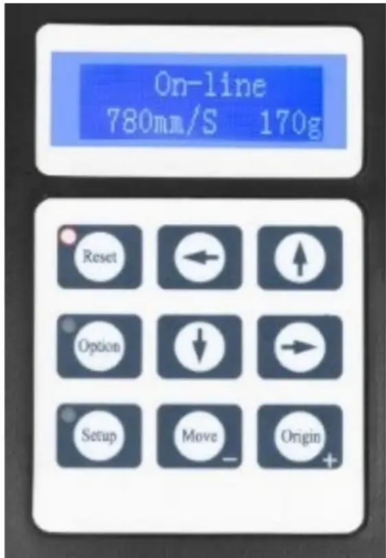
Technical line drawing of a mechanical or electrical component with a square base and circular vented area (no text or symbols)DISPLAY, CONTROL PANEL AND SETTINGS

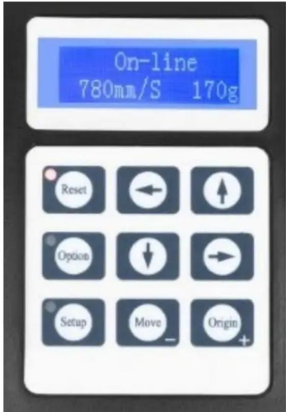
The main screen allows to set the main settings of the cutter like the cutting speed, cutting force and cut a test pattern or check the amount of force that is currently set. Main screen options:
| “Reset” | Resets the operation of the machine and set the carriage arm to its right most position. |
| “Option” | Enter the offline-/pause-mode. |
| “Setup” | Enter the setup mode. |
| “Move” | Cuts a small test shape for testing the current force and speed settings. Used to determine the proper cutting speed and force settings needed for different materials without wasting a bigger piece of them. |
| “Origin” | Used to test z-axis functionality (by dropping the blade down if the carriage is functioning properly) or to set a new origin point when the machine is in offline-mode. |
| ↓/↑ | Adjusts the cutting speed. A cutting speed of 300 mm/s is a (reasonable) default speed that can be used for most cuts. When working with smaller and more detailed images, a slower speed may be required. When working with larger and less detailed images, a higher speed can be set for shortening the operation time. |
| ←/→ | Adjusts the cutting force. A cutting force of 100g is a good general starting place to work from when trying to determine the force needed for a specific material. All cuttable materials will tear in the amount of force needed so proper testing should always be made to determine the right amount of used force.A proper amount of force is when the blade fully penetrates the material to be cut while not cutting through the backing material. |
Offline-mode is used to reposition the cutting material and blade so that a new starting position can be set for the next design. This mode can also be accessed while the machine is in operation and will pause the current cutting process. Although changes can be made to the material and blade positions if offline-/pause-mode is entered during cutting, but making changes to either setting is not normally recommended. Offline mode options:
| “Reset” | Resets the operation of the machine and set the carriage arm to its right most position. |
| “Option” | Ignores any changes that have been made to the material or blade positions and exits offline-/pause-mode, returning the machine to the main screen. Resumes any cutting that was taking place when offline-/pause-mode was entered. |
| “Setup” | Without function in this mode. |
| “Move” | Accepts any changes that have been made to the material or blade positions and exits offline-/pause-mode returning the cutter to the main screen. Resumes any cutting that was taking place when offline-/pause-mode was entered from the new blade/material positions. |
| “Origin” | Accepts any changes that have been made to the material or blade positions and exits offline-/pause mode returning the cutter to the main screen. Resumes any cutting that was taking place when Offline-/pause-mode was entered from the new blade/material positions. |
| ↓/↑ | Reposition the material by moving the feed rollers. After movements being made we can confirm the changes by pressing the “Move” or “Origin” buttons or cancel it by pressing the “Option” button. |
| ←/→ | Reposition the blade by moving the carriage arm. After movements being made we can confirm the changes by pressing the “Origin” buttons or cancel by pressing the “Option” button. |
OPERATION
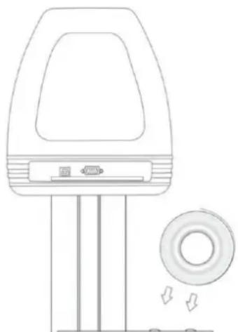
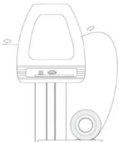
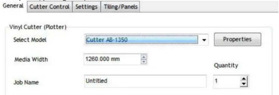
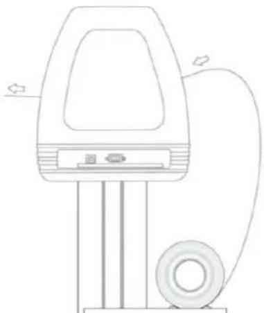
- Place the roll on top of the stand rollers. For heat press vinyl, please flip the roll:
natural_image
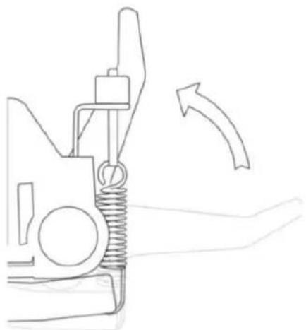
Line drawing of a handheld device with a circular button and directional arrows, no text or symbols present.- Release the pinch rollers release levers:
natural_image
Line drawing of a mechanical spring assembly with an arrow indicating direction (no text or symbols)- Feed the vinyl underneath the pinch rollers (if working from a single sheet instead of a roll, the vinyl can also be feed from the front):
natural_image
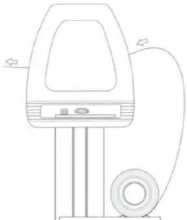
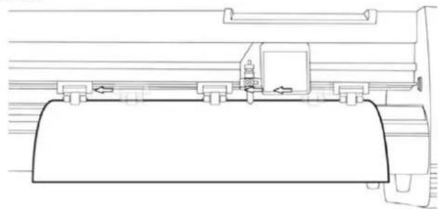
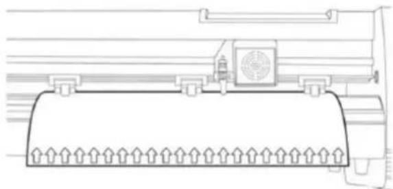
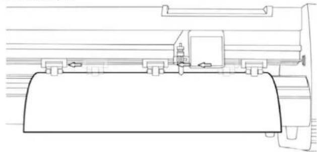
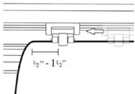
Line drawing of a handheld electric shock absorber with attached circuit board (no text or symbols)- Adjust the pinch rollers so there is one roller located on each side of the vinyl (and, on models with 3 or more rollers, one roller near the center). Avoid lowering a pinch roller to the gap between the two feed rollers:
natural_image
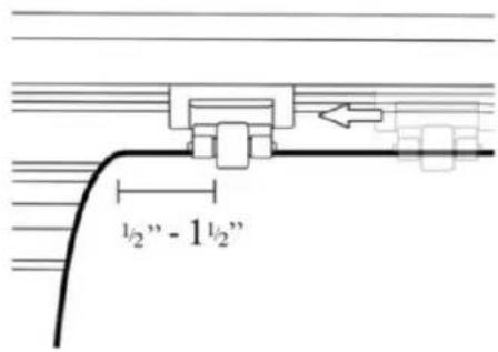
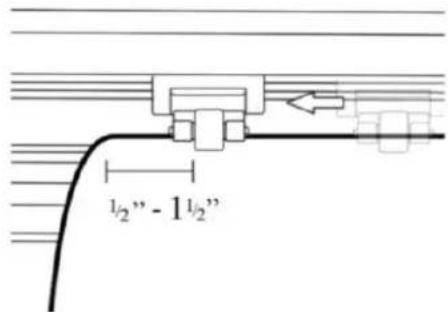
Technical line drawing of a mechanical assembly or component (no text or symbols visible)- Leave a gap of between 1.27 - 3.8 mm (1/2"-1 1/2") from the edge of the roller and the edge of the vinyl on both sides:
-
Engage the pinch rollers by pushing down on the pinch roller release levers.
-
Turn on the machine (if not been turned on yet).
Changing cutting position
-
Press the "Option" button to enter the offline-mode.
-
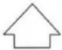
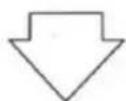
Adjust the vinyl to where you want to make your cut to start by using the up and down arrow buttons on the control panel:
natural_image
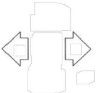
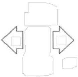
Technical line drawing of a mechanical component with no visible text or symbols- Now, adjust the blade to where you want your cut to start by using the left and right arrow buttons:
natural_image
Abstract geometric shape with four arrows pointing inward, no text or symbols present
natural_image
Technical line drawing of a mechanical assembly with springs and housing (no text or symbols)-
Now press the "Origin" button to tell the cutter that this is the location where you would like the cut to begin.
-
NOTE: When choosing a starting location for your design, remember that the process will start in the bottom right area of the design. Leave enough room to the left of and behind the starting location to finish the cut.
If you would like to make other adjustments to the pressure, speed or other settings you can do so now. If you are setting up for your first cut with the machine then the default values should be a good starting point.
If you make any adjustments to your cutter, make sure that you return to the main screen before you attempt to cut.
Software operation
-
Attach the power cord to the cutter and then plug in the unit and turn on the power.
-
If you are using a serial cable to connect the machine to a computer then no further setup is necessary. Simply connect one end of the cable to the machine and the other end to a computer and setup is complete. If you have more than one serial connection on your computer or you are experiencing communication issues between the machine and computer then you may to verify that the correct COM-port is being used in your software setup, but for most users the COM port will be COM1.
-
If using USB cable to connect the machine to a computer than installation software (SignMaster) needed – shown in further steps. The driver is automatically installed during software installation, no need to install the driver separately.
-
Open the software box, take the disk and put it into CD optical drive or alternatively put the USB flash disc with software driver on it.
-
[If the installation hasn't started automatically] Open the computer, double click or right click optical drive to install the software:

- Click on the icon in the red box and start installing the software and choose the installation language:

- Agree the software terms and click next to proceed:

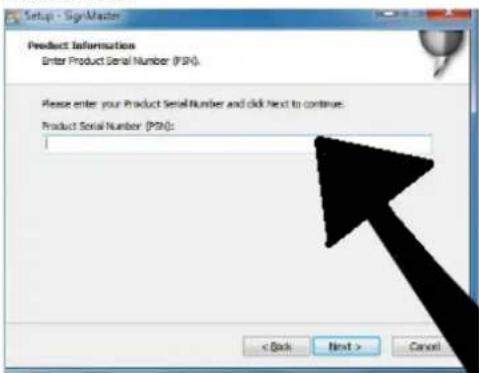
- Enter the product serial number (PSN) in the window - the PSN-code can be found at left side of opened softwarebox:
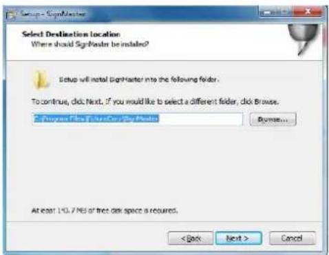
- Follow the default installation path – choose the installation folder and click next:
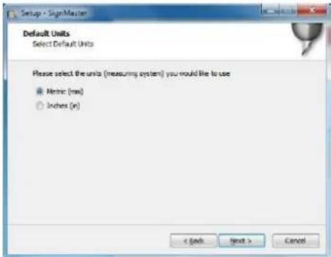
- Select units system (metric or imperial):

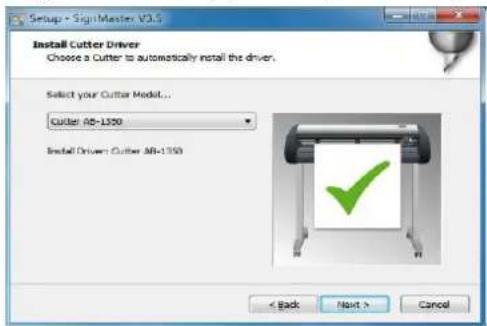
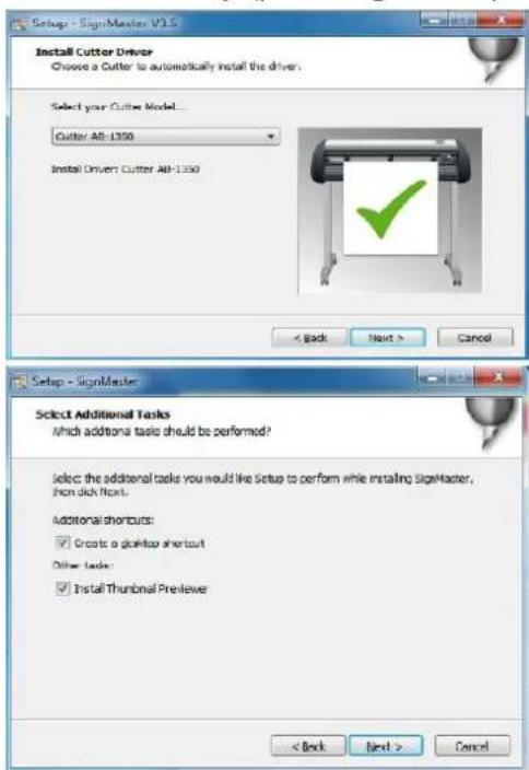
- Select the machine model (check it on the label on the machine body) and click next:
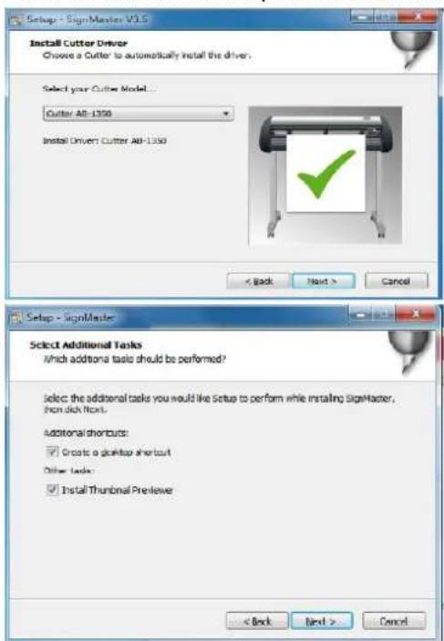
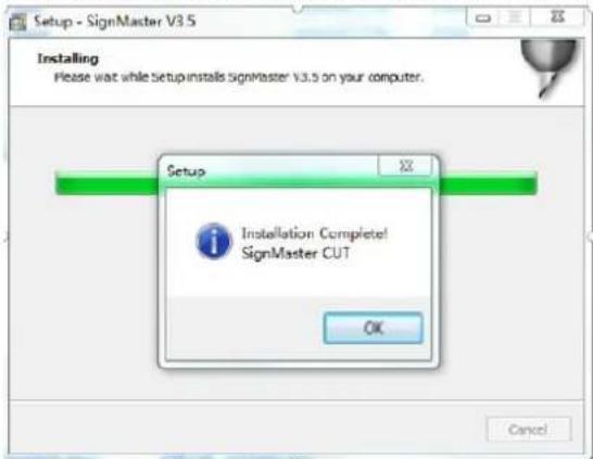
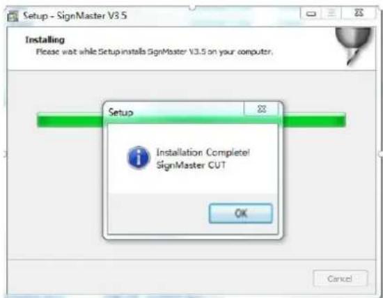
- The installation is complete if You see this window appears on the screen:

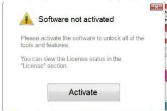
- When opening the software for the first time, the activation window appears:
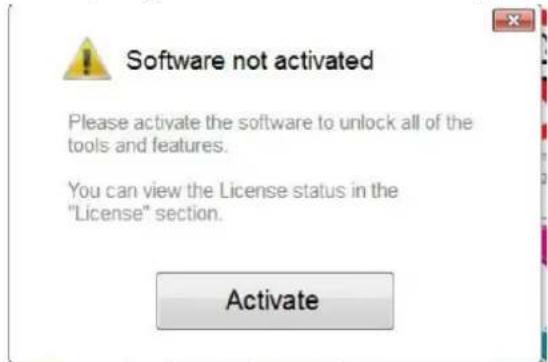
- Click "Activate" button and enter Your email:
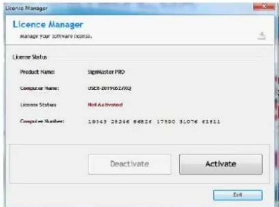
- After successfully activating the software, click "Exit" on the window:

Connectiong the software with the machine
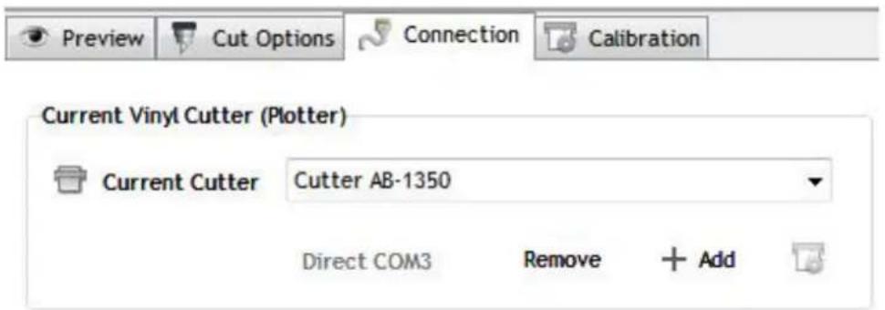
- Open the software, select the desired content and click sent to the cutting plotter. Click the cutter icon marked below:
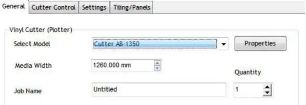
![SignMaster CUT 3.5 - [*Untitled.vDoc] File Edit View Layout Arrange Objects Images Text Curves Colors Tool x 20.732 mm H→H 56.758 mm y 69.734 mm 55.600 mm Corner Style Round -300 -250 -200 -150 -100 -5 General Cutter Control Settings Tiling/Panels](/content/2026/04/714232/images/94efc5dcb6475aef5ea8043aab8ee05518892818233596f0de6914a284bbc610.jpg)
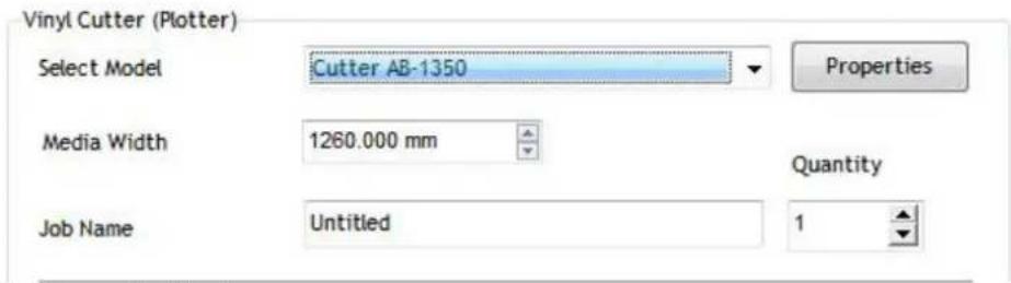
- Click "Properties" button:
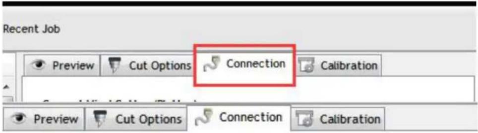
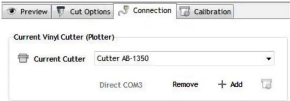
- Click "Connection" tab and select machine model:

- Select direct USB port:

- Drop-down selected driver:

- Click "Finish: button and then "Cut Now":
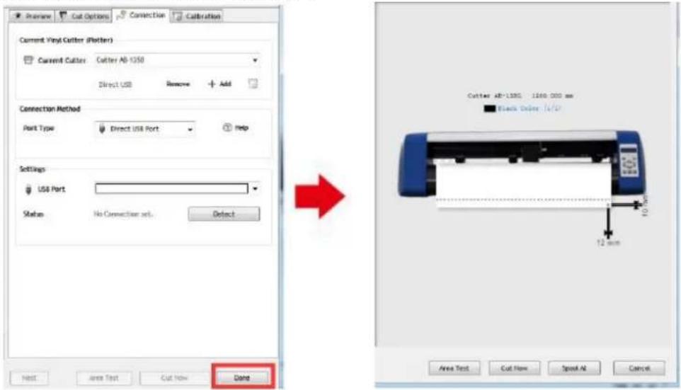
- Select "Yes" to proceed with cutting:

NOTE: Software installation video manual is also included on the USB flash drive.
TROUBLESHOOTING
| Problem | Solution |
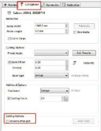
| Machine cannot connect to software. | Software port settings, as shown below: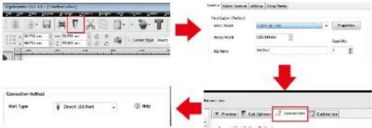 |
| Paper deviation occurred during cutting | Because the tension of paper press is inconsistent, rotate the two yellow brass nuts on each paper press to the same height, then the pressure is balanced, as shown below: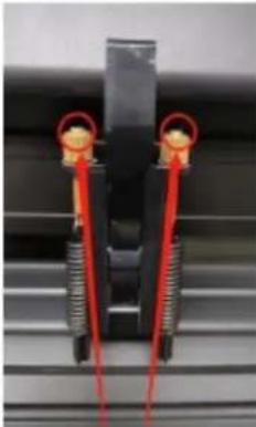 Rotate them to the same height. Rotate them to the same height. |
| The effect of small graphics cutting is not ideal. | When the cutting height is 3-5 mm letters, the software compensation value is set to 0.45 and the speed is adjusted to 400 mm/s. When the cutting height is more than 5 mm letters, the software compensation value is set to 0.3 and the speed is adjusted to 600 mm/s or more: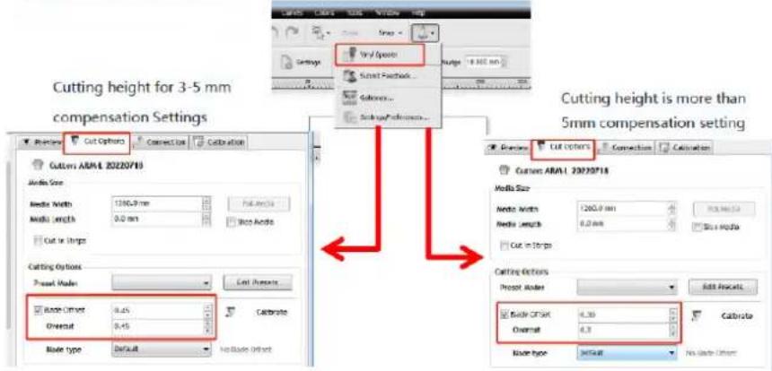 |
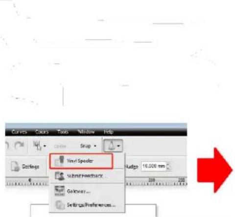
| Often repeated cutting, cutting before automatic paper and other problems. | Cancel the automatic paper feeding function after cutting in the software, as shown below: |
 |  | |
| The cutting process stops and does not return to the origin. | Do not use any data conversion connector. Data may be lost and the cutting process may stop. Please plug the data line directly into the computer interface. | |
DISPOSING OF USED DEVICES
Do not dispose of this device in municipal waste systems. Hand it over to an electric and electrical device recycling and collection point. Check the symbol on the product, instruction manual and packaging. The plastics used to construct the device can be recycled in accordance with their markings. By choosing to recycle you are making a significant contribution to the protection of our environment.
Contact local authorities for information on your local recycling facility.

natural_image
Cross-sectional diagram of a mechanical component with internal structure and labeled X (no text or symbols beyond label)
natural_image
Technical line drawing of a mechanical component with a square housing and circular vent pattern (no text or symbols)natural_image
Technical line drawing of a mechanical device with a perforated panel and adjustment tool (no text or symbols)natural_image
Technical line drawing of a mechanical component with a square base and circular vent-like pattern (no text or symbols)WYŚWIETLACZ, PANEL STEROWANIA I USTAWIENIA
natural_image
Line drawing of a handheld device with a circular button and directional arrows (no text or symbols)natural_image
Line drawing of a mechanical clamp or spring assembly with an arrow indicating rotational motion (no text or symbols)natural_image
Line drawing of a handheld electric shock absorber with a coiled cable (no text or symbols)natural_image
Cross-sectional diagram of a mechanical component with internal structure and liquid level (no text or symbols)
natural_image
Technical line drawing of a mechanical component with a square base and circular vented pattern (no text or symbols)natural_image
Technical line drawing of a mechanical device with a perforated panel and cylindrical components (no text or symbols)natural_image
Technical line drawing of a mechanical or electrical component with a square base and circular vented pattern (no text or symbols)DISPLEJ, OVLÁDACÍ PANEL A NASTAVENÍ

natural_image
Line drawing of a handheld device with a circular button and directional arrows, no text or symbols present.natural_image
Line drawing of a mechanical spring assembly with an arrow indicating direction (no text or symbols)natural_image
Line drawing of a handheld device with a scroll wheel and indicator lights (no text or symbols)natural_image
Technical line drawing of a mechanical assembly or component (no text or symbols visible)natural_image
Technical line drawing of a mechanical component with no visible text or symbolsnatural_image
Abstract geometric shape with four arrows pointing inward, no text or symbols present
natural_image
Technical line drawing of a mechanical assembly with no visible text or symbols
natural_image
Cross-sectional diagram of a mechanical component with internal structure and labeled 'X' (no text or symbols within the diagram itself)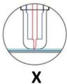
natural_image
Technical line drawing of a mechanical component with a square base and circular vent-like pattern (no text or symbols)natural_image
Technical line drawing of a mechanical device with a perforated panel and screwdriver (no text or symbols)natural_image
Technical line drawing of a mechanical component with a square base and circular vented pattern (no text or symbols)AFFICHAGE, PANNEAU DE COMMANDE ET PARAMÈTRES

natural_image
Line drawing of a handheld device with a circular button and directional arrows (no text or symbols)natural_image
Line drawing of a mechanical spring assembly with an arrow indicating direction (no text or symbols)natural_image
Line drawing of a portable electric shaver with a coiled cable (no text or symbols)natural_image
Technical line drawing of a mechanical assembly with no visible text or symbolsnatural_image
Technical line drawing of a mechanical component with no visible text or symbols
natural_image
Technical line drawing of a mechanical assembly with springs and housing (no text or symbols)natural_image
Cross-sectional diagram of a mechanical component with internal structure and labeled X (no text or symbols beyond label)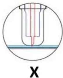
natural_image
Cross-sectional diagram of a test tube with red liquid and blue cap, labeled 'X' (no text or symbols within the diagram itself)natural_image
Technical line drawing of a mechanical component with a square base and circular vent-like pattern (no text or symbols)natural_image
Technical line drawing of a mechanical device with a perforated panel and cylindrical component (no text or symbols)natural_image
Technical line drawing of a mechanical component with a square base and circular vent-like pattern (no text or symbols)natural_image
Line drawing of a handheld device with a circular button and directional arrows (no text or symbols)natural_image
Line drawing of a mechanical spring assembly with an arrow indicating rotational motion (no text or symbols)natural_image
Line drawing of a handheld electric shaver with a coiled cable (no text or symbols)natural_image
Technical line drawing of a mechanical assembly with no visible text or symbolsnatural_image
Technical line drawing of a mechanical component with no visible text or symbols
natural_image
Abstract geometric shape with four arrows pointing inward, no text or symbols present
natural_image
Technical line drawing of a mechanical assembly with no visible text or symbolsnatural_image
Cross-sectional diagram of a mechanical component with internal structure and labeled X (no text or symbols beyond label)
natural_image
Technical line drawing of a mechanical component with a square housing and circular vent pattern (no text or symbols)natural_image
Technical line drawing of a mechanical device with a perforated panel and cylindrical component (no text or symbols)natural_image
Technical line drawing of a mechanical component with a square housing and circular vented pattern (no text or symbols)natural_image
Line drawing of a handheld device with a circular button and directional arrows (no text or symbols)natural_image
Line drawing of a mechanical spring assembly with an arrow indicating direction (no text or symbols)natural_image
Line drawing of a handheld electric shaver with a coiled cable (no text or symbols)natural_image
Technical line drawing of a mechanical assembly or component (no text or symbols visible)natural_image
Technical line drawing of a mechanical component with no visible text or symbols
natural_image
Abstract geometric diagram with four arrows pointing inward from a central shape (no text or symbols)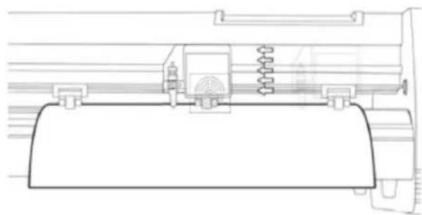
natural_image
Technical line drawing of a mechanical assembly with springs and housing (no text or symbols)natural_image
Cross-sectional diagram of a mechanical component with internal structure and liquid level (no text or symbols)
natural_image
Technical line drawing of a mechanical component with a square base and circular vent-like pattern (no text or symbols)natural_image
Technical line drawing of a mechanical device with a perforated panel and cylindrical component (no text or symbols)natural_image
Technical line drawing of a mechanical component with a square base and circular vent-like pattern (no text or symbols)KIJELZŐ, VEZÉRLÓPANEL ÉS BEÁLLÍTÁSOK

natural_image
Line drawing of a handheld device with a circular button and directional arrows (no text or symbols)natural_image
Line drawing of a mechanical spring assembly with an arrow indicating direction (no text or symbols)natural_image
Line drawing of a handheld electric shock absorber with a coiled cable (no text or symbols)natural_image
Technical line drawing of a mechanical assembly or mounting bracket (no text or symbols)natural_image
Technical line drawing of a mechanical component with no visible text or symbolsnatural_image
Abstract geometric shape with four arrows pointing inward, no text or symbols present
natural_image
Technical line drawing of a mechanical assembly with no visible text or symbols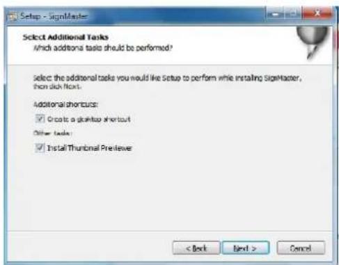

natural_image
Cross-sectional diagram of a mechanical component with internal structure and labeled X (no text or symbols beyond label)
natural_image
Cross-sectional diagram of a test tube with red liquid and blue cap, labeled 'X' (no text or symbols within the diagram itself)natural_image
Technical line drawing of a mechanical or electronic component with a central fan-like structure and mounting bracket (no text or symbols)natural_image
Technical line drawing of a mechanical device with a perforated panel and screwdriver (no text or symbols)natural_image
Technical line drawing of a mechanical component with a perforated base and mounting bracket (no text or symbols)DISPLAY, KONTROLPANEL OG INDSTILLINGER

natural_image
Line drawing of a handheld device with a circular button and directional arrows (no text or symbols)natural_image
Line drawing of a mechanical spring assembly with an arrow indicating direction (no text or symbols)natural_image
Line drawing of a handheld electric shaver with a coiled cable (no text or symbols)natural_image
Cross-sectional diagram of a mechanical component with internal structure and labeled X (no text or symbols beyond label)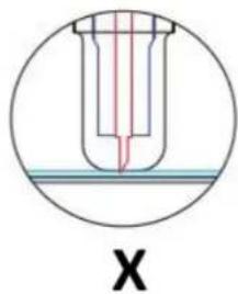
natural_image
Cross-sectional diagram of a test tube with red liquid and blue cap, labeled 'X' (no text or symbols within the diagram itself)natural_image
Technical line drawing of a mechanical component with a perforated circular feature and mounting bracket (no text or symbols)natural_image
Technical line drawing of a mechanical device with a perforated panel and screwdriver (no text or symbols)natural_image
Technical line drawing of a mechanical component with a perforated base and mounting bracket (no text or symbols)natural_image
Line drawing of a handheld device with a circular button and directional arrows indicating motion (no text or symbols)natural_image
Line drawing of a mechanical spring assembly with an arrow indicating direction (no text or symbols)natural_image
Line drawing of a handheld electric shock absorber with a coiled cable (no text or symbols)natural_image
Technical line drawing of a mechanical assembly or mounting bracket (no text or symbols)natural_image
Technical line drawing of a mechanical component with no visible text or symbolsnatural_image
Abstract geometric shape with four arrows pointing inward, no text or symbols present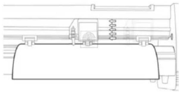
natural_image
Technical line drawing of a mechanical assembly with springs and housing (no text or symbols)

natural_image
Cross-sectional diagram of a mechanical component with internal structure and labeled X (no text or symbols beyond label)
natural_image
Technical line drawing of a mechanical component with a square base and circular vented pattern (no text or symbols)natural_image
Technical line drawing of a mechanical device with a perforated panel and cylindrical components (no text or symbols)natural_image
Technical line drawing of a mechanical component with a square housing and circular vented pattern (no text or symbols)WEERGAVE, BEDIENINGSPANEELE EN INSTELLINGEN

natural_image
Line drawing of a handheld device with a circular button and directional arrows (no text or symbols)natural_image
Line drawing of a mechanical clamp or spring assembly with an arrow indicating direction (no text or symbols)natural_image
Line drawing of a handheld electric shaver with a coiled cable (no text or symbols)natural_image
Technical line drawing of a mechanical assembly with no visible text or symbolsnatural_image
Technical line drawing of a mechanical component with no visible text or symbols
natural_image
Abstract geometric shape with four arrows pointing inward, no text or symbols present
natural_image
Technical line drawing of a mechanical assembly with springs and housing (no text or symbols)- Selecteer directe USB-poort:

- Skinneføringsdeksel
- Klemrullesett
- Matepapirrulle
- Vogn
- Tilbakestill bryteren
- Utstilling
- Kontrollpanel
- Høyre sidedeksel
- Bladklemme
- Venstre sidedeksel
- Strømtilkoplingsuttak
- Sikringsholder
- Strømbryter
- USB-port
- COM-port
- Stå
- Tilbehør
STANDMONTERING
| 1 | *6 | |
| 2 | *4 | |
| 3 | *4 | |
| 4 | *4 | |
| 5 | *6 | |
| 6 | *8 | |
| 7 | *4 |
KNIVMONTERING
FESTING AV KNIVET I HOLDEREN
a) Pressstang
b) Bladdeksel
c) Blad
d) Shank
e) Bladjusteringsmutter
natural_image
Cross-sectional diagram of a mechanical component with internal structure and liquid level (no text or symbols)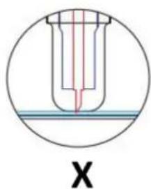
INSTALLERE KNIVHOLDEREN I BÆRELEN
natural_image
Technical line drawing of a mechanical component with a square base and circular vented pattern (no text or symbols)natural_image
Technical line drawing of a mechanical device with a perforated panel and cylindrical components (no text or symbols)natural_image
Technical line drawing of a mechanical or electrical component with a square base and circular vented pattern (no text or symbols)DISPLAY, KONTROLLPANEL OG INNSTILLINGER

natural_image
Line drawing of a handheld device with a circular button and three vertical supports (no text or symbols)natural_image
Line drawing of a mechanical spring assembly with an arrow indicating direction (no text or symbols)- Mat vinylen under klemrullene (hvis du arbeider fra et enkelt ark i stedet for en rull, kan vinylen også mates fra forsiden):
natural_image
Line drawing of a handheld electric shock absorber with attached circuit board (no text or symbols)natural_image
Technical line drawing of a mechanical assembly or mounting bracket (no text or symbols)- La det være mellom 1,27 – 3,8 mm (1/2"-1 1/2") fra kanten av valsen og kanten av vinylen på begge sider:
natural_image
Two simple arrow symbols: one upward and one downward, both outlined in black outline (no text or labels)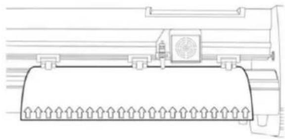
natural_image
Technical line drawing of a mechanical component with no visible text or symbolsnatural_image
Technical line drawing of a mechanical assembly with no visible text or symbols- Velg maskinmodell (sjekk den på etiketten på maskinhuset) og klikp på Neste:

Koble programvaren til maskinen
- Velg direkte USB-port:

- Rullegardin valgt driver:

natural_image
Technical line drawing of a mechanical component with a square base and circular vent-like pattern (no text or symbols)natural_image
Technical line drawing of a mechanical device with a perforated panel and cylindrical components (no text or symbols)natural_image
Technical line drawing of a mechanical component with a square housing and circular vented pattern (no text or symbols)DISPLAY, KONTROLLPANELEN OCH INSTÄLLNINGAR

natural_image
Line drawing of a handheld device with a circular button and directional arrows (no text or symbols)natural_image
Line drawing of a mechanical clamp or spring assembly with an arrow indicating direction (no text or symbols)natural_image
Line drawing of a handheld electric shaver with a coiled cable (no text or symbols)natural_image
Technical line drawing of a mechanical assembly or component (no text or symbols visible)natural_image
Technical line drawing of a mechanical component with no visible text or symbols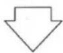
natural_image
Abstract geometric shape with four arrows pointing inward, no text or symbols present
natural_image
Technical line drawing of a mechanical assembly with spring and housing (no text or symbols)
- Klicka på knappen "Egenskaper":

- Välj direkt USB-port:

- Rulla ned vald drivrutin:

natural_image
Cross-sectional diagram of a mechanical component with internal structure and labeled X (no text or symbols beyond label)
natural_image
Technical line drawing of a mechanical component with a square base and circular vented pattern (no text or symbols)natural_image
Technical line drawing of a mechanical device with a perforated panel and cylindrical components (no text or symbols)natural_image
Technical line drawing of a mechanical or electrical component with a square base and circular vented pattern (no text or symbols)natural_image
Line drawing of a handheld device with a circular button and directional arrows (no text or symbols)natural_image
Line drawing of a mechanical spring assembly with an arrow indicating rotational motion (no text or symbols)natural_image
Line drawing of a handheld electric shaver with a coiled cable (no text or symbols)natural_image
Technical line drawing of a mechanical assembly or component (no text or symbols visible)natural_image
Two simple arrow symbols: an upward-pointing arrow and a downward-pointing arrow, both outlined in black (no text or labels)
natural_image
Technical line drawing of a mechanical component with no visible text or symbolsnatural_image
Abstract geometric diagram with four arrows pointing inward from a central shape (no text or symbols)
natural_image
Technical line drawing of a mechanical assembly with springs and housing (no text or symbols)- Seleccione o sistema de unidades (métrico ou imperial):

- Seleccione "Sim" para prosseguir com o corte:

natural_image
Line drawing of a handheld device with a circular button and directional arrows (no text or symbols)natural_image
Line drawing of a mechanical spring assembly with an arrow indicating rotational motion (no text or symbols)natural_image
Line drawing of a handheld electric shaver with a coiled cable (no text or symbols)natural_image
Technical line drawing of a mechanical assembly or mounting bracket (no text or symbols)- Ponechajte medzeru medzi 1,27 – 3,8 mm (1/2"-1 1/2") od okraja valčeka a okraja vinylu na oboch stranách:

natural_image
Technical line drawing of a mechanical component with no visible text or symbols- Teraz pomocou tlačidiel so šípkou dolava a doprava nastavte čepel na miesto, kde chcete, aby rez začal:
natural_image
Abstract geometric shape with four arrows pointing inward, no text or symbols present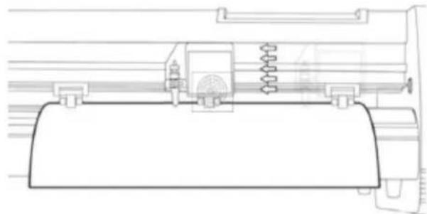
natural_image
Technical line drawing of a mechanical assembly with springs and housing (no text or symbols)- Vyberte model stroja (skontrolujte ho na štítku na tele stroja) a kliknite na d'alej:


- Inštalácia je dokončená, ak sa na obrazovke zobrazí toto okno:
- Kliknite na kartu „Pripojenie“ a vyberte model stroja:

- Vyberte priamy port USB:
- Rozbal'ovací zoznam vybratého ovládača:
- Kliknite na tlačidlo „Dokončit:“ a potom na „Vystrihnút“:
- Ak chcete pokračovať v rezaní, vyberte „Áno“:
natural_image
Cross-sectional diagram of a mechanical component with internal structure and labeled X (no text or symbols beyond label)
natural_image
Technical line drawing of a mechanical component with a circular vent and mounting bracket (no text or symbols)natural_image
Technical line drawing of a mechanical device with a perforated panel and cylindrical component (no text or symbols)natural_image
Technical line drawing of a mechanical component with a perforated base and mounting bracket (no text or symbols)ДИСПЛЕЙ, КОНТРОЛЕН ПАНЕЛ И НАСТРОЙКИ
natural_image
Line drawing of a handheld device with a circular button and directional arrows (no text or symbols)natural_image
Line drawing of a mechanical spring assembly with an arrow indicating rotational motion (no text or symbols)natural_image
Line drawing of a handheld electric shaver with a coiled cable (no text or symbols)natural_image
Technical line drawing of a mechanical assembly with no visible text or symbolsnatural_image
Technical line drawing of a mechanical component with no visible text or symbols
natural_image
Technical line drawing of a mechanical assembly with springs and housing (no text or symbols)- Изберете директен USB порт:

natural_image
Cross-sectional diagram of a mechanical component with internal structure and labeled X (no text or symbols beyond label)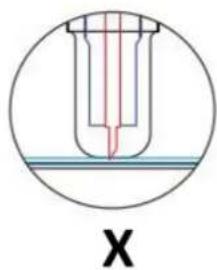
natural_image
Technical line drawing of a mechanical component with a perforated circular feature and mounting bracket (no text or symbols)natural_image
Technical line drawing of a mechanical device with a perforated panel and cylindrical component (no text or symbols)natural_image
Technical line drawing of a mechanical component with a circular vent and mounting bracket (no text or symbols)natural_image
Line drawing of a handheld device with a circular button and vertical supports (no text or symbols)natural_image
Line drawing of a mechanical spring assembly with an arrow indicating direction (no text or symbols)natural_image
Line drawing of a handheld electric shaver with a coiled cable (no text or symbols)natural_image
Technical line drawing of a mechanical component or assembly (no text or symbols visible)natural_image
Two simple arrow symbols: one upward and one downward, both outlined in black outline (no text or labels)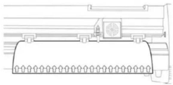
natural_image
Technical line drawing of a mechanical component with no visible text or symbolsnatural_image
Abstract geometric shape with four arrows pointing inward, no text or symbols present
natural_image
Technical line drawing of a mechanical assembly with no visible text or symbols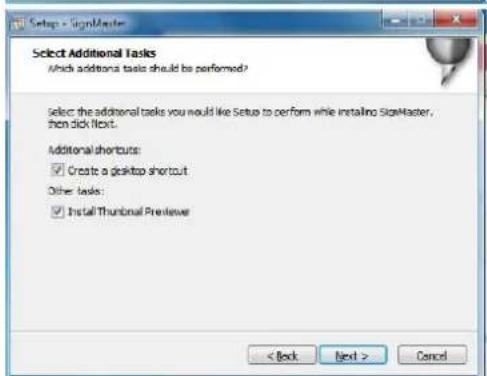

- Poklopac vodilice tračnice
- Komplet potisnih valjaka
- Valjak za uvlačenje papira
- Prijevoz
- Reset prekidač
- Prikaz
- Upravljačka ploča
- Desni bočni poklopac
- Stezaljka oštrice
- Lijevi bočni poklopac
- Utičnica za napajanje
- Držač osigurača
- Prekidač napajanja
- USB priključak
- COM priključak
- stajati
- Pribor
MONTAŽA STALKA
| 1 | *6 | |
| 2 | *4 | |
| 3 | *4 | |
| 4 | *4 | |
| 5 | *6 | |
| 6 | *8 | |
| 7 | *4 |
SKLOP OŠTRICE
| 1. Odvijte poklopac s nosača oštrica. | 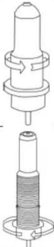 | ||
| 2. Postavite mjedeni prsten na nosaču oštrice u krajnji donji položaj. | |||
| 3. Uklonite zaštitni poklopac s nove oštrice. | [T521] | ||
| 4. Umetnite oštricu u gornji dio nosača oštrice. | | ||
| 5. Zavrnite poklopac natrag na nosač oštrice. | 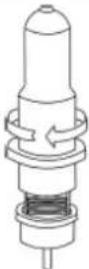 | ||
| 6. Podesite poklopac nosača dok oštrica ne bude virila približno 0,4 mm. | 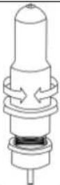 |
natural_image
Cross-sectional diagram of a mechanical component with internal structure and labeled X (no text or symbols beyond label)
natural_image
Cross-sectional diagram of a test tube with red liquid and blue cap, labeled 'X' (no text or symbols within the diagram itself)A) Debljina materijala
B) Debljina baze
V) Ispravna dubina rezanja
X) Lijevo – vrh oštrice predug; Desno – vrh oštrice je prekratak
natural_image
Technical line drawing of a mechanical or electronic component with a central fan-like structure and mounting bracket (no text or symbols)natural_image
Technical line drawing of a mechanical device with a perforated panel and screwdriver (no text or symbols)natural_image
Technical line drawing of a mechanical component with a perforated base and mounting bracket (no text or symbols)ZASLON, UPRAVLJAČKA PLOČA I POSTAVKE

Glavni zaslon omogućuje postavljanje glavnih postavki rezača kao što su brzina rezanja, sila rezanja i rezanje probnog uzorka ili provjera količine sile koja je trenutno postavljena. Opcije glavnog zaslona:
| “Reset” | Ponovno postavite rad stroja i postavite polugu nosača u krajnji desni položaj. |
| “Option” | Uđite u izvanmrežni/pauzirani način rada. |
| “Setup” | Uđite u način postavljanja. |
| “Move” | Reže mali probni oblik za testiranje trenutnih postavki sile i brzine. Koristi se za određivanje pravilne brzine rezanja i postavki sile potrebne za različite materijale bez rasipanja većeg komada istih. |
| “Origin” | Koristi se za testiranje funkcionalnosti z-osi (spuštanjem oštrice prema dolje ako nosač radi ispravno) ili za postavljanje nove ishodišne točke kada je stroj u izvanmrežnom načinu rada. |
| ↓ / ↑ | Podešava brzinu rezanja. Brzina rezanja od 300 mm/s je (razumna) zadana brzina koja se može koristiti za većinu rezova. Kada radite s manjim i detaljnijim slikama, možda će biti potrebna manja brzina. Kod rada s većim i manje detaljnim slikama, može se podesiti veća brzina radi skraćivanja vremena rada. |
| ← / → | Podešava silu rezanja. Sila rezanja od 100 g dobro je opće početno mjesto za rad kada pokušavate odrediti silu potrebnu za određeni materijal. Svi materijali koji se mogu rezati pokidat će se pod silom koja je potrebna, stoga uvijek treba provesti odgovarajuće testiranje kako bi se odredila točna količina korištene sile. |
Odgovarajuća količina sile je kada oštrica u potpunosti prodre u materijal koji treba rezati, a ne reže kroz materijal podloge.
natural_image
Line drawing of a mechanical clamp or spring assembly with an arrow indicating direction (no text or symbols)- Uvucite vinil ispod potisnih valjaka (ako radite s jednim listom umjesto role, vinil se također može uvlačiti s prednje strane):
natural_image
Line drawing of a handheld device with a circular base and cable, no text or symbols present- Podesite potisne valjke tako da se jedan valjak nalazi sa svake strane vinila (i, na modelima s 3 ili više valjaka, jedan valjak blizu sredine). Izbjegavajte spuštanje potisnog valjka do razmaka između dva uvlačna valjka:
natural_image
Technical line drawing of a mechanical assembly with no visible text or symbols- Ostavite razmak između 1,27 – 3,8 mm (1/2"-1 1/2") od ruba valjka i ruba vinila s obje strane:

natural_image
Technical line drawing of a mechanical component with no visible text or symbolsnatural_image
Abstract geometric shape with four arrows pointing inward, no text or symbols present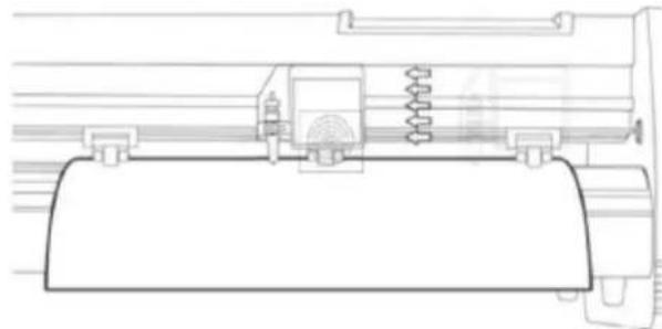
natural_image
Technical line drawing of a mechanical assembly with no visible text or symbols- Unesite serijski broj proizvoda (PSN) u prozor - PSN-kod se nalazi na lijevoj strani otvorene programske kutije:

- Odaberite sustav jedinica (metrički ili imperijalni):
- Instalacija je dovršena ako vidite da se na ekranu pojavljuje ovaj prozor:
- Prilikom prvog otvaranja softvera pojavljuje se prozor za aktivaciju:
- Kliknite gumb "Aktiviraj" i unesite svoju e-poštu:

natural_image
Cross-sectional diagram of a mechanical component with internal structure and labeled X (no text or symbols beyond label)
natural_image
Cross-sectional diagram of a test tube with red liquid and blue cap, labeled 'X' (no text or symbols within the diagram itself)natural_image
Technical line drawing of a mechanical component with a perforated circular feature and mounting bracket (no text or symbols)natural_image
Technical line drawing of a mechanical device with a perforated panel and adjustment tool (no text or symbols)natural_image
Technical line drawing of a mechanical component with a square housing and circular vented pattern (no text or symbols)EKRANAS, VALDYMO SKYDELIS IR NUSTATYMAI

natural_image
Line drawing of a handheld device with a circular button and directional arrows indicating motion (no text or symbols)natural_image
Line drawing of a mechanical clamp or spring assembly with an arrow indicating direction (no text or symbols)natural_image
Line drawing of a handheld device with a circular base and cable, no text or symbols presentnatural_image
Technical line drawing of a mechanical assembly with no visible text or symbolsnatural_image
Technical line drawing of a mechanical component with no visible text or symbolsnatural_image
Abstract geometric shape with four arrows pointing inward, no text or symbols present
natural_image
Technical line drawing of a mechanical assembly with no visible text or symbols
natural_image
Cross-sectional diagram of a mechanical component with internal structure and labeled X (no text or symbols beyond label)
natural_image
Technical line drawing of a mechanical component with a square base and circular vented pattern (no text or symbols)natural_image
Technical line drawing of a mechanical device with a perforated panel and cylindrical components (no text or symbols)natural_image
Technical line drawing of a mechanical component with a square housing and circular vented pattern (no text or symbols)natural_image
Line drawing of a handheld device with a circular button and directional arrows (no text or symbols)natural_image
Line drawing of a mechanical spring assembly with an arrow indicating rotational motion (no text or symbols)natural_image
Line drawing of a handheld electric shaver with a coiled cable (no text or symbols)natural_image
Technical line drawing of a mechanical assembly or mounting bracket (no text or symbols)natural_image
Technical line drawing of a mechanical component with no visible text or symbolsnatural_image
Abstract geometric shape with three arrows pointing inward (no text or symbols)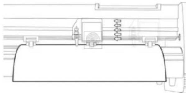
natural_image
Technical line drawing of a mechanical assembly with no visible text or symbols
- Selectati portul USB direct:

- Driverul selectat derulant:

natural_image
Technical line drawing of a mechanical component with a square base and circular vented pattern (no text or symbols)- Namestite nosilec rezila v režo za roko nosilca.

natural_image
Technical line drawing of a mechanical device with a perforated panel and cylindrical components (no text or symbols)natural_image
Technical line drawing of a mechanical component with a square base and circular vented pattern (no text or symbols)ZASLON, NADZORNA PLOŠČA IN NASTAVITVE

natural_image
Line drawing of a handheld device with a circular button and directional arrows, no text or symbols present.natural_image
Line drawing of a mechanical spring assembly with an arrow indicating motion (no text or symbols)natural_image
Line drawing of a portable electronic device with a cylindrical base and cable, no text or symbols presentnatural_image
Technical line drawing of a mechanical assembly or component (no text or symbols visible)- Pustite razmik med 1,27 – 3,8 mm (1/2"-1 1/2") od roba valja in roba vinila na obeh straneh:
natural_image
Technical line drawing of a mechanical component with no visible text or symbols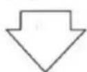
natural_image
Abstract geometric shape with four arrows pointing inward (no text or symbols)
natural_image
Technical line drawing of a mechanical assembly with no visible text or symbols- Izberite model stroja (preverite ga na nalepki na ohišju stroja) in kliknite naprej:
- Kliknite gumb "Aktiviraj" in vnesite svoj e-poštni naslov:

Povezava programske opreme s strojem
- Kliknite gumb "Lastnosti":

- Izberite neposredna vrata USB:

For the disposal of the device please consider and act according to the national and local rules and regulations.
CONTACT
expondo Polska sp. z o.o. sp. k.