WOOHS-7HP - Band saw MSW - Free user manual and instructions
Find the device manual for free WOOHS-7HP MSW in PDF.

User questions about WOOHS-7HP MSW
0 question about this device. Answer the ones you know or ask your own.
Ask a new question about this device
Download the instructions for your Band saw in PDF format for free! Find your manual WOOHS-7HP - MSW and take your electronic device back in hand. On this page are published all the documents necessary for the use of your device. WOOHS-7HP by MSW.
USER MANUAL WOOHS-7HP MSW
PbKOBOCTBO3A YIOTPEBA
O△HΓIΕΣXPHΣHΣ
UPUTEZAUPORABU
NAUDOJIMO INSTRUKCIJA
MANUAL DE UTILIZARE
NAVODILA ZA UPORABO
HORIZONTAL BAND SAW
| DE | Produktname | Blockbandsäge |
| EN | Product name | Horizontal Band Saw |
| PL | Nazwa produktu | Pila taśmowa do kłód drewna |
| CZ | Název výrobku | Horizontální pásová pila |
| FR | Nom du produit | Scie à ruban horizontally |
| IT | Nome del prodotto | Sega a nastro orizzontale |
| ES | Nombre del producto | Sierra de cinta horizontal |
| HU | Termék neve | Víszintes szalagfúrész |
| DA | Produktnavn | Vandret bändsav |
| FI | Tuotteen nimi | Vaaka-nauhasaha |
| NL | Productnaam | Horizontalite lintzaag |
| NO | Produktnavn | Horizontal bändsag |
| SE | Produktnamn | Horizontell bandsåg |
| PT | Nome do produits | Serra de fita horizontal |
| SK | Názov produktu | Horizontálna pásová pila |
| BG | Иme на песукта | Хорионтalem lentов трион |
| EL | Оvoцma пюіóνтоц | Оріцόvyцma пioювокорбéлα |
| HR | Naziv proizvoda | Horizontalna tračna pila |
| LT | Produkto pavadinimas | Horizontalali juostinépjūklas |
| RO | Numele produsului | Fierăstrău cu bandă orizzontală |
| SL | Ime izdelka | Vodoravna tračna zhaga |
| DE Modell | EN Product model |PL Model Produktu|CZ Model vyrobku | FR Modèle |IT Modello | ES Modelo | HU Modell |DA Model | FI Tuotteen malli |NL Productmodel | NO Produktmodel |SE Produktmodell | PT Modelo do produits|SK Model | BG(Model na песукт|EL Mòtvělo προǐóνtoç | HR Modelproizvoda | LT: Gaminio modelis | RO:Model de produs | SL: Model izdelka | MSW-WOOHS-7HPMSW-WOOHS-E3600K | |
| DE Hersteller | EN Manufacturer |PL Producent | CZ Výrobce |FR Fabricant | IT Produttore |ES Fabricante | HU Termelő |DA Producent | FI Valmistaja |NL Producent | NO Produsent |SE Tillverkare | PT Fabricante|SK Výrobca | BG Пoinizboydintel|EL Kátακειαστήç | HR Proizvodač|LT Gamintojas | RO Produçător|SL Proizvajalec | expendo Polska sp. z o.o. sp. k. | |
| DE Anschrift des Herstellers |EN Manufacturer Address | PL Adresproducenta | CZ Adresa vyrobce |FR Adresse du fabricant | IT Indirizzo delproduttore | ES Dirección del fabricante |HUA gyártó cime | DA Producentadenasse | FI Valmistajan osoite|NL Adres producent | NO Produentsaddress | SE Tillverkarens adress|PT Endereço do fabricante | SK Adresa výrobcu | BG Ädrec na proinizboydintel|EL:Дiocúθυνούη κατακειαστή | HR Adresaproizvodača | LT Gamintojo adresas|RO Adresa producătorului | SL Naslovproizvajalca | ul. Nowy Kisielin - Innowacyjna 7, 66-002 Zielona Góra | Poland, EU |

This User Manual has been translated for your convenience using machine translation. Reasonable efforts have been made to provide an accurate translation; however, no automated translation is perfect nor is it intended to replace human translators. The official User Manual is the English version. Any discrepancies or differences created in the translation are not binding and have no legal effect for compliance or enforcement purposes. If any questions arise related to the accuracy of the information contained in the User Manual, please refer to the English version of those contents which is the official version.
Technical data
| Parameter description Parameter value | |
| Product name | Horizontal Band Saw |
| Model | MSW-WOOHS-7HP |
| Engine Power [kW] | 4.1 |
| Engine Speed [rpm] | 3600 |
| Blade Speed [m/s] | 14 |
| Max Cutting Capacity [mm] | 457 |
| Dimensions [width x depth x height; mm] | 1250 x 1340 x 3000 |
| Weight [kg] | 156 |
| Parameter description Parameter value | |
| Product name | Horizontal Band Saw |
| Model | MSW-WOOHS-E3600K |
| Rated voltage [V~] / frequency [Hz] | 230/50 |
| Rated power [W] | 2600 |
| Motor Speed [rpm] | 2800 |
| Protection rating IP | IP44 |
| Blade Speed [m/s] | 14 |
| Max Cutting Capacity [mm] | 457 |
| Dimensions [width x depth x height; mm] | 1350 x 1240 x 3000 |
| Weight [kg] | 152 |

WARNING:
Read carefully and understand all INSTRUCTIONS before operating. Failure to follow the safety rules and other basic safety precautions may result in serious personal injury.
FOREWORD
This machine is designed for certain applications only. We strongly recommend this machine is not modified and/or used for any application other than that for which it was designed. If you have any questions relative to a particular application, DO NOT use the machine until you have first contacted us to determine if it can or should be performed on the product.
INTENDED USE
This sawmill is designed for sawing logs while the mill is firmly supported on the ground.
GENERAL SAFETY RULES

WARNING: Read and understand all instructions. Failure to follow all instructions listed below is a result in electric shock, fire and/or serious injury.

WARNING: The warnings, cautions, and instructions discussed in this instruction manual do not cover all possible conditions or situations that could occur. It must be understood by the operator that common sense and caution are factors which cannot be built into this product, but can be supplied by the operator.
WORK AREA
- Keep work area clean, free of clutter and well lit. Cluttered and dark work areas can cause accidents.
- Do not use your sawmill where there is a risk of causing a fire or an explosion; e.g. In the presence of flammable liquids, gasses, or dust. Power tools create sparks, which may ignite the dust or fumes.
- Keep children and bystanders away while operating a power tool. Distractions can cause you to lose control, so visitors should remain at a safe distance from the work area.
- Be aware of all power lines, electrical circuits, water pipes and other mechanical hazards in your work area, particularly those hazards below the work surface hidden from the operator's view that may be unintentionally contacted and may cause personal harm or property damage.
- Be alert of your surroundings. Using power tools in confined work area may put you dangerously close to cutting tools and rotating parts.
PERSONAL SAFETY
- Stay alert, watch what you are doing and use common sense when operating a power tool. Do not use a power tool while you are tired or under the influence of drugs, alcohol or medication. A moment of inattention while operating power tools may result in serious personal injury.
- Dress properly. Do not wear loose clothing, dangling objects, or jewellery. Keep your hair, clothing and gloves away from moving parts. Loose clothes, jewellery or long hair can be caught in moving parts. Air vents often cover moving parts and should be avoided.
- Use safety apparel and equipment. Use safety goggles or safety glasses with side shields which comply with current national standards, or when needed, a face shield.
- Use as dust mask in dusty work conditions. This applies to all persons in the work area. Also use non-skid safety shoes, hardhat, gloves, dust collection systems, and hearing protection when appropriate.
- Do not over reach. Keep proper footing and balance at all times.
- Remove adjusting keys or wrenches before connecting to the power supply or turning on the tool. A wrench or key that is left attached to a rotating part of the tool may result in personal injury.
- Never make blade guide adjustments, remove or install blades or conduct any other maintenance or make any other adjustments when the engine is running.
TOOL USE AND CARE
- Always be sure operator is familiar with proper safety precautions and operation techniques before using machine.
- Avoid "kick-back" by knowing what conditions can create it.
- Do not force the tool. Tools do a better and safer job when used in the manner for which they are designed.
-
Never use the sawmill with a malfunctioning switch. Any power tool that cannot be controlled with the switch is dangerous and must be repaired before using.
-
Turn off the engine and place the switch in the locked or off position before servicing, adjusting, installing accessories or attachments, or storing. Such preventive safety measures reduce the risk of starting the power tool accidentally.
- Secure logs with the log screw clamping device instead of with your hand or another individual's help. This safety precaution allows for proper tool operation using both hands.
- Storing sawmill. When the sawmill is not use, store it in a dry, secure place or keep well covered and out of the reach of children. Inspect the sawmill for good working condition prior to storage and before re-use.
- Maintain your sawmill. It is recommended that the general condition of the sawmill be examined before it is used. Keep your sawmill in good repair by adopting a program of conscientious repair and maintenance in accordance with the recommended procedures found in this manual. If any abnormal vibrations or noise occurs, turn the sawmill off immediately and have the problem corrected before further use.
- Keep saw blades sharp and clean. Properly maintained band saw blades are less likely to bind and are easier to control.
- Cleaning and Lubrication. Use only soap and a damp cloth to clean your sawmill.
Many household cleaners are harmful to plastic and rubber components on the sawmill.
- Use only accessories that are recommended by the manufacturer for your model. Accessories that may be suitable for another sawmill may create a risk of injury when used on the sawmill.
- Always operate machine with all safety devices and guards in place and in working order. DO NOT modify or make changes to safety devices. DO NOT operate machine if any safety devices or guards are missing or inoperative.
- Never leave sawmill running unattended.
- Coiled blades can spring apart with considerable force and unpredictably in any direction. Always deal with coiled blades, including those packaged in boxes, with the utmost care.
- Never use the equipment to cut anything other than lumber or for any purpose other than cutting lumber as described in this manual.
START UP PROCEDURE - EQUIPMENT OPERATION
- Wear heavy-duty work gloves, ANSI-approved goggles behind a full-face shield, steel-toed work boots, and a dust mask.
- Operate only with assistance.
- Ensure guide blocks are tight and track is level.
- Fill the lubrication tank with clean water and washing up detergent.
- Start and operate the engine.
- Cut branches off the lumber to be processed.
- WARNING: To avoid death or serious injury, Do not cut lumber with foreign objects in it such as nails, any metal pieces, etc.
- Place the lumber to be cut on the supports.
- WARNING: The operator and any assistants must stay clear of the front and back of the blade whenever the engine is ON.
- Move the saw head slowly along the track and against the lumber to make the cut.
- Trim off the rounded sides of the log.
- When the log is squared-off, boards or posts can be cut to custom specifications.
GENERAL MAINTENANCE INFORMATION
Proper and routine maintenance is critical to operator safety, achieving good milling results and to prolonging the life of your investment.
- Band Wheel Bearing --- Should be inspected before use to ensure they are not worn. Bearings are sealed and do not need to be greased.
- Blade Guide Bearing --- Inspect before use for excessive grooves or scoring in the bearing case. Replace if necessary.
- Blade Tension --- Grease threads of tensioning "T" handle when dry or as required. Use multipurpose, extreme-pressure grease.
- Log Screws --- Grease frequently.
- Belts --- Periodically check the condition and wear of the drive and idler belt. Ensure that the blade does not ride on the band wheels.
- Drive Belt --- Periodically check the tension of the drive belt. It should deflect by no more than 1/2'' (12.5 mm).
- Saw head Locking Cam Handles --- Grease assembly every 30 days or as required.
- Saw head Vertical Posts --- Spray posts before use with a silicone spray lubrication such as 3-in-1 or Jig-A-Loo.
- Band wheel Guards --- Routinely remove any build-up of sawdust that may collect inside the band wheel guards.
- Lubrication Tank --- Only fill with a water/washing up detergent mixture (one to two caps) or in winter months, use windshield washer fluid. Do not leave lubricant in tank if temperatures fall below 0^ .
- Blade Lubricant --- Never use diesel fuel or kerosene as blade lubricant. These substances lead to premature wear of your belts and poor sawing performance. For winter operations, replace the water lubricant with windshield washer fluid.
- Saw head Lifting Cables --- Regularly before, during and after operations, inspect the cables for any wear or kinks. Ensure that the cables are in perfect condition. Oil coiled part of cable often to prevent premature wear. Replace with new cables as necessary.
SAWMILL ASSEMBLY PARTS INSPECTION
A. Take all of the parts out of the shipping crate and lay them out.
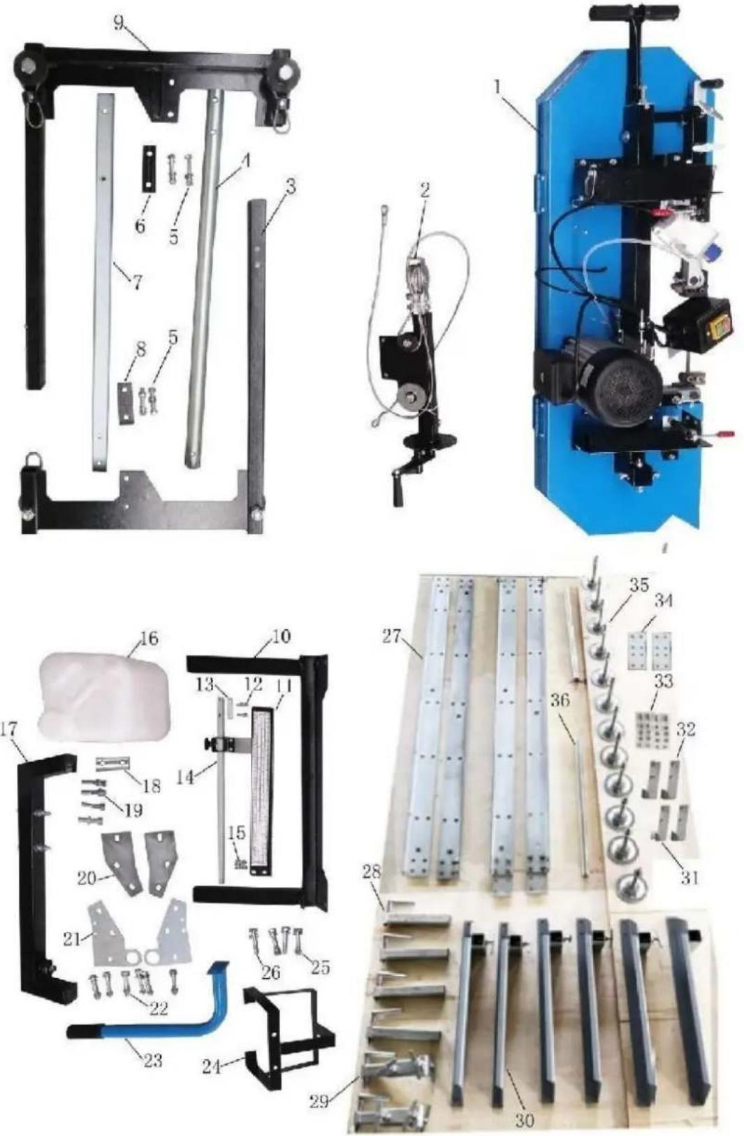
B. Check all the parts in according to blow parts list.
| NO. | DESCRIPTION | Qty. | NO. | DESCRIPTION | Qty. |
| 1 | SAW HEAD | 1 | 19 | HEX BOLT M10X55 | 4 |
| WASHER 10mm | 4 | ||||
| SPRING WASHER 10mm | 4 | ||||
| 2 | STEEL ROPE HOLDER COMPLETE | 1 | 20 | JOINT PLATE B | 2 |
| 3 | LEFT VERTICAL FRAME | 1 | 21 | JOINT PLATE A | 2 |
| 4 | ROUND SUPPORT | 1 | 22 | HEX BOLT M10X70 | 6 |
| WASHER 10mm | 12 | ||||
| SPRING WASHER | 6 | ||||
| 10mm | 6 | ||||
| HEX BOLT M10 | 6 | ||||
| 5 | HEX BOLT M12X70 | 4 | 23 | PUSH-PULL HANDLE | 1 |
| WASHER 12mm | 4 | ||||
| SPRING WASHER 12mm | 4 | ||||
| HEX NUT M12 | 4 | ||||
| 6 | SPACER PLATE C | 1 | 24 | SUPPORT POST FOR TANK | 1 |
| 7 | SQUARE POST | 1 | 25 | HEX BOLT M10X65 | 2 |
| WASHER 10mm | 4 | ||||
| SPRING WASHER | 2 | ||||
| 10mm | 2 | ||||
| HEX NUT M10 | 2 | ||||
| 8 | SPACER PLATE B | 1 | 26 | HEX BOLT M10X65 | 2 |
| WASHER 10mm | 2 | ||||
| SPRING WASHER 10mm | 2 | ||||
| 9 | RIGHT VERTICAL FRAME | 1 | 27 | GUIDE RAIL | 4 |
| 10 | STRENGTHEN BRACKET | 1 | 28 | FIXED CLAMP ASM | 4 |
| 11 | SCALE BRACKET(WITH SCALE) | 1 | 29 | MOVABLE CLAMP ASM | 2 |
| 12 | HEX BOLT M6X25 | 2 | 30 | CROSS ARM ASM | 6 |
| WASHER 6mm | 2 | ||||
| 13 | SPACER BLOCK | 1 | 31 | STOPPER NO.1 | 2 |
| 14 | POINTER COMPLETE | 1 | 32 | STOPPER NO.2 | 2 |
| 15 | HEX BOLT M8X16 | 2 | 33 | HEX BOLT | 48 |
| WASHER 8mm | 2 | M10X25 HEX | 48 | ||
| HEX NUT M8 | 2 | NUT M10 HEX | 4 | ||
| BOLT M12X25 | 4 | ||||
| WASHER 12mm | |||||
| 16 | COOLANTTANKWITH PLASTIC TUBE | 1 | 34 | JOINT PLATE | 2 |
| 17 | JOINT BRACKET WITH BOLTS | 1 | 35 | FOOT PAD WITH NUT & WASHER | 12 |
| 18 | SPACER PLATE A | 1 | 36 | SLIDING BAR | 2 |
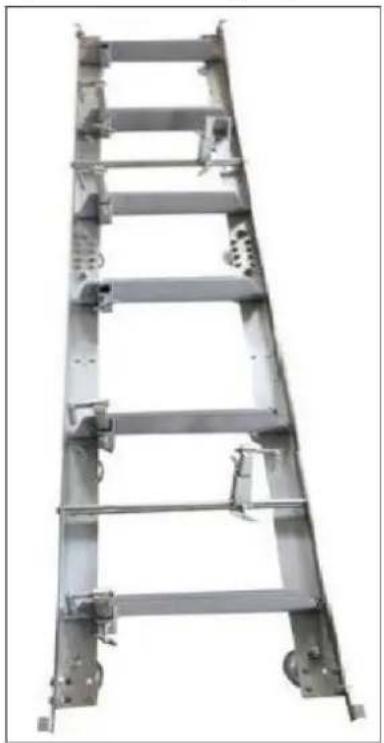
TRACKS ASSEMBLY
Assemble track system and secure loosely with provided nuts & bolts. It is important not to fully tighten the bolts at this stage. This will be done after the head is assembled and rolled along the track. It is ideal to assemble the tracks on a solid and level footing that is a minimum of 4^ off the ground - We recommend you attach the levelling legs to sleepers which we discuss later in the instruction manual. This will allow for easy cleanup of sawdust from under the tracks and height adjustment of the log supports and also easier levelling of the track.
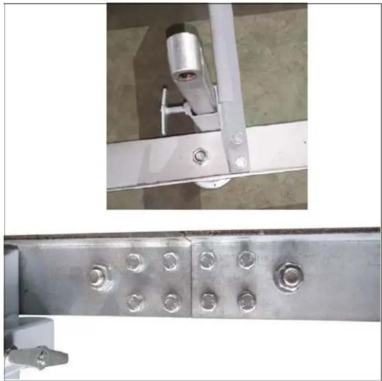
Attach track cross supports to "L" channel with the provided nuts & bolts. The joining plate is used at the seam joint to join the two sections together (shown in top right image). Ensure to only hand tighten at this stage. The bolts will be fully tightened once the head assembly is free to roll on the tracks and provide the correct track width.
Assemble carriage stops at the ends of the tracks (4 stops total) and tighten.
LOGDOG&SUPPORTS
Assemble log dog pieces as shown below and use water proof grease on threaded handle and "T" handle. Attach assembly to the track using the provided nuts & bolts and tighten.
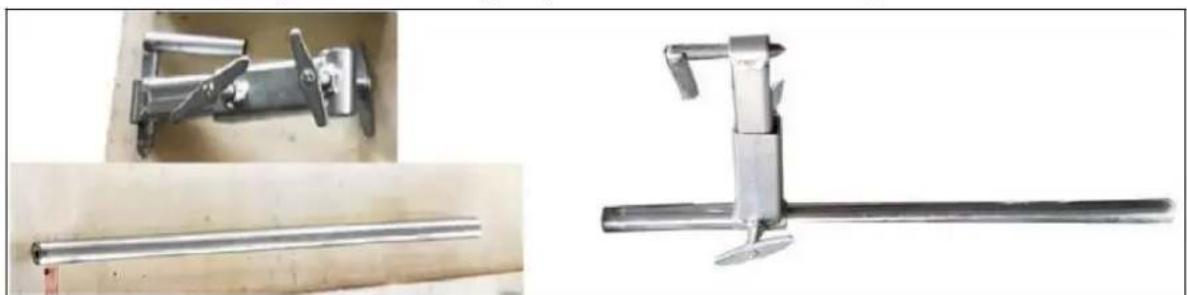
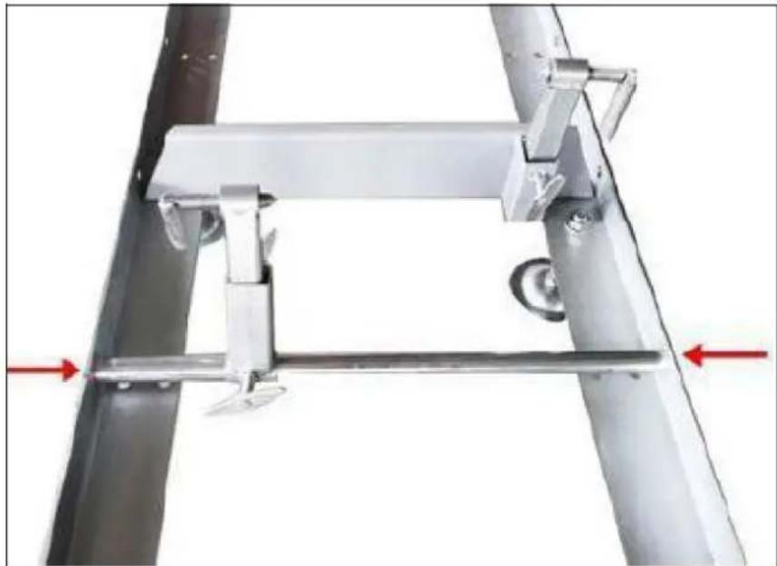
Attach log dog assembly to track as shown below with 2 bolts and washers provided. Note that there are various locations along the track where this assembly can be bolted. Depending on how many track sections are being used, select a log clamp position that will secure the log firmly against the log supports.
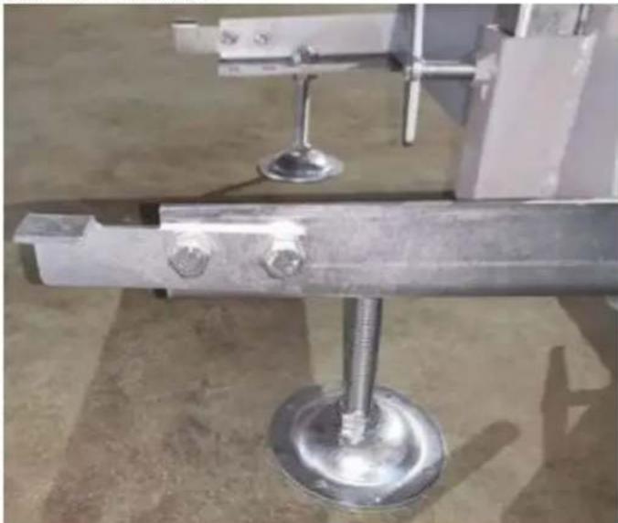
Insert log supports into track cross supports and secure with "T" handles. The "T" handle thread should be coated with waterproof grease.
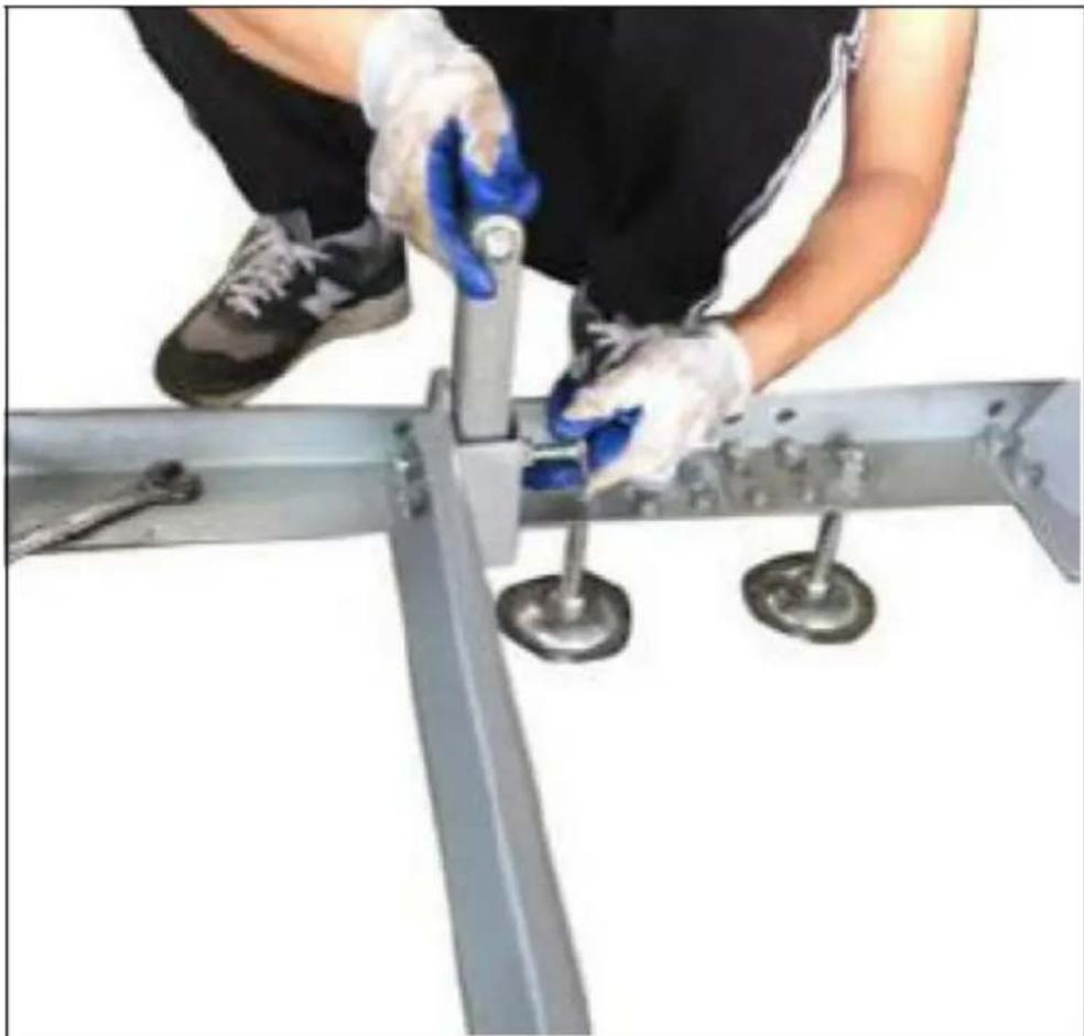
Make the cross arm on the tracks at same level
Note:
If the ground is not hard floor and not level, you can insert some wood blocks under the track.
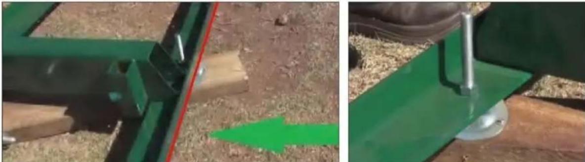
We recommend screwing the levelling legs onto the sleepers after the mill has been levelled. Therefore, before screwing the mill to the sleepers, it is recommended to run a string line on both sides of the mill to ensure that the track is straight and level.
The red arrows indicate the locations of the levelling legs are. There are six per 1.5 metres of track, 12 in total on the machine. On the intermediate bunks the levelling legs alternate. We recommend placing the mill levelling legs on sleepers running left to right as shown above. You need to make sure the bunks are also level. To do this you use a spirit level going left to right on top of each bunk and also using a string line down the length of the track. The string line needs to be approx. 10mm above the bunks.

Carriage assembly
Place a moving blanket on the shipping pallet that the sawmill crate was strapped to. The blanket will prevent the blade guard covers from becoming scratched. Using a minimum of two people or a mechanical advantage system, remove the head assembly from the sawmill crate and place face down on the blanket. The head assembly is very heavy, proper technique must be used to avoid injury or damage.
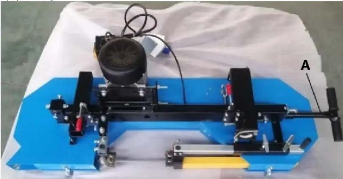
A-Blade tension
Find the square and round columns, and insert the round one into the sliding tube close to blade tension system, and insert square one into the sliding tube on the other side, and fix two vertical post by the locking handle. Attention to the stop bolt on the square column.
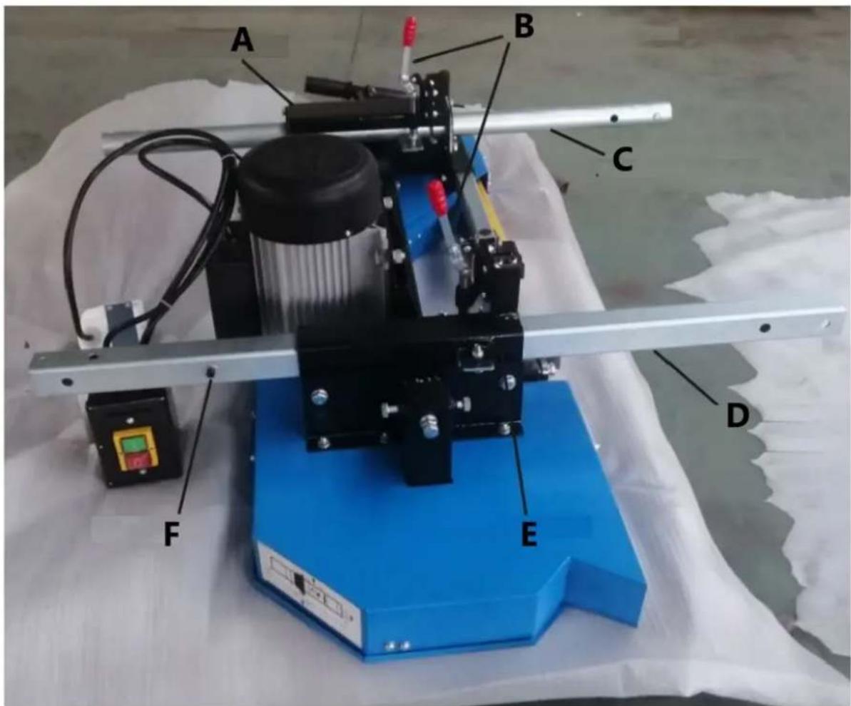
A-Sliding tube
B-Locking handle
C-Round column
D-Square column
E-Sliding tube
F-Stop bolt
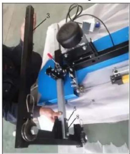
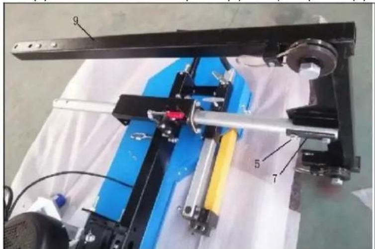
Connect the Left vertical frame (3) to the Square column as shown by bolts (5) and Space plate B (8). And then connect the Right vertical frame (9) to the Round column by bolts (5) and Space plate C (6).
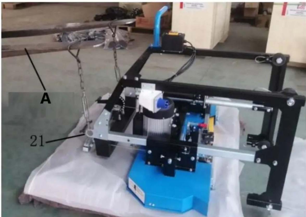
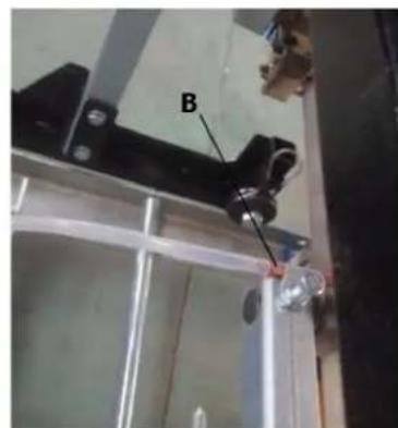
Connect the Joint bracket (17) to the Square column and Round column by bolts (19) and Space plate A (18). Loosen the bolts and nuts on the Joint bracket, and fix the Steel rope holder as picture showing.
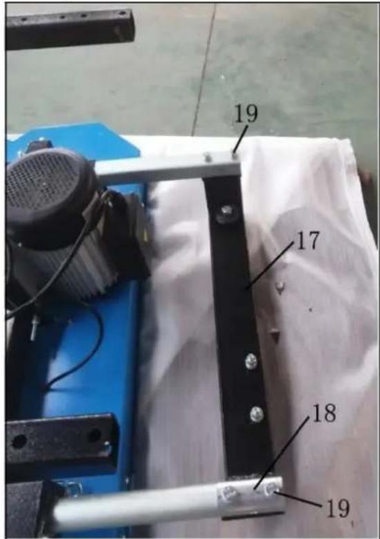
A-Rope-1 B-Bolts and nuts C-Rope-2
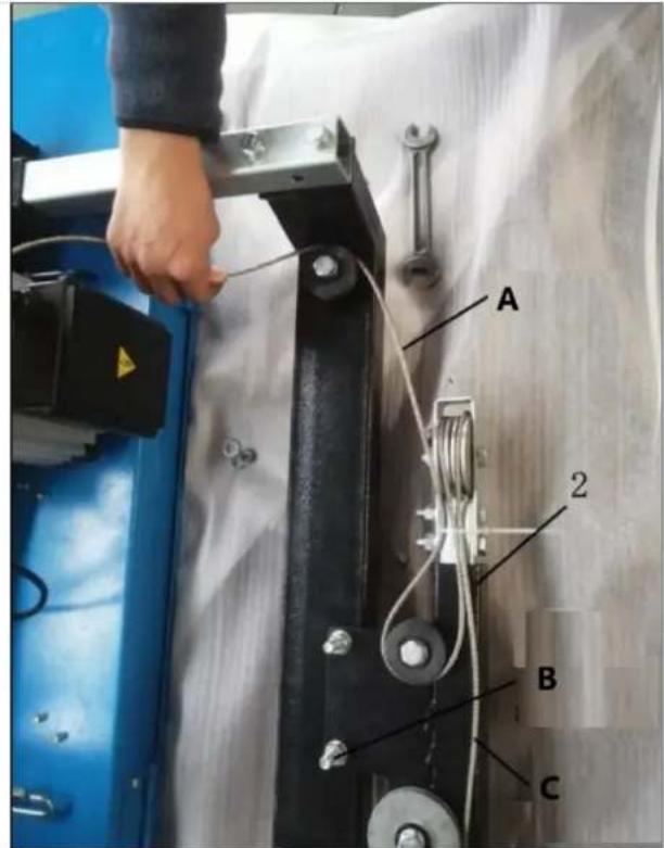
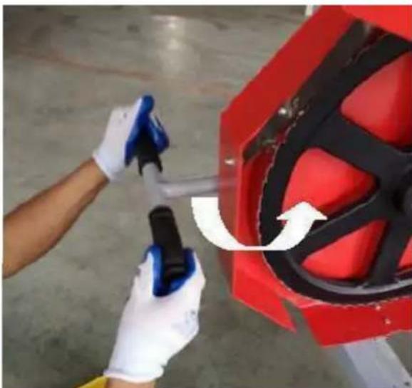
Loosen the Chain nut on machine head, Let the Steel rope across the pulley, fix two ends of Steel rope to the holders, tighten the Chain nut. Swing the Lift handle to make the steel rope tighten. Lock the Locking handles.
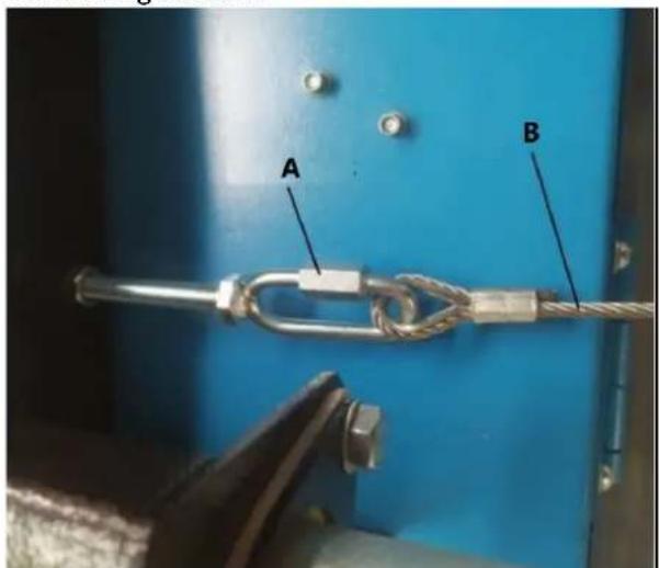
A-Chain nut B-Steel rope C-Steel rope D-Lift handle
E-Locking handle
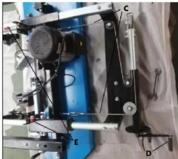
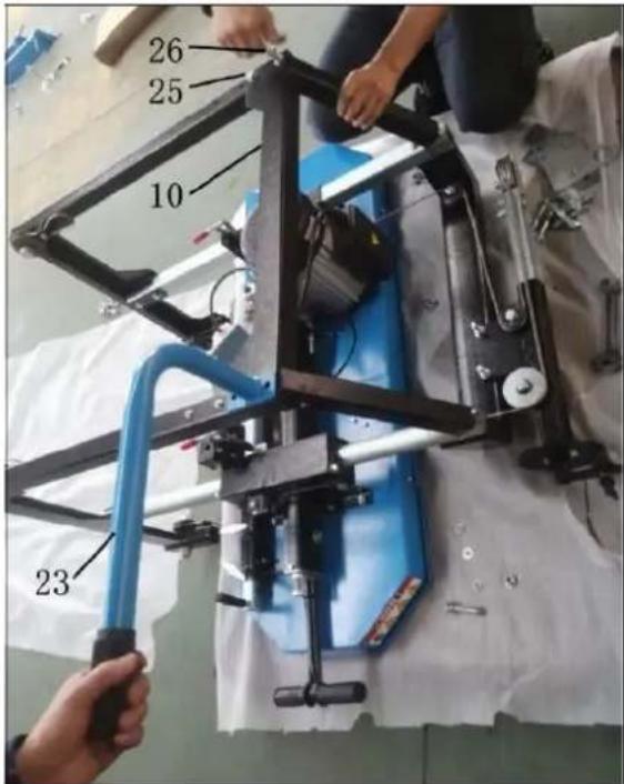
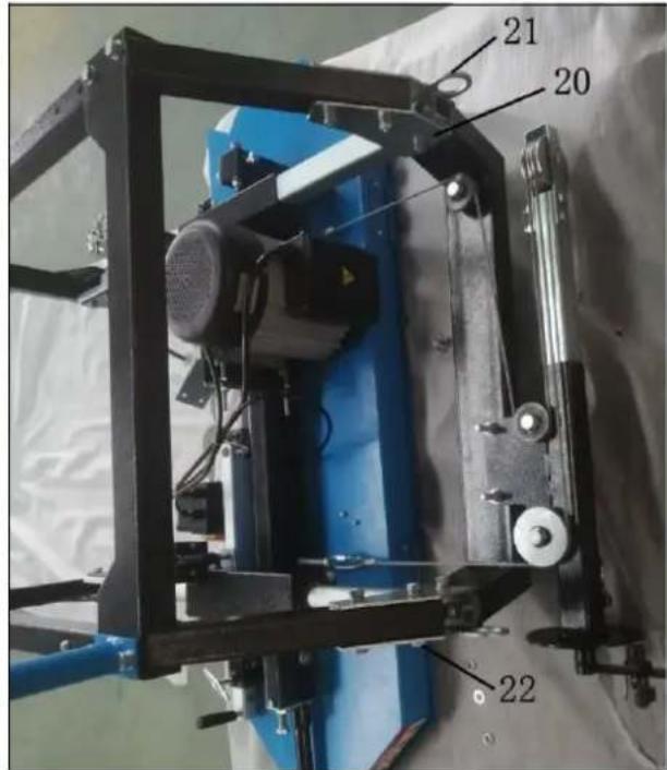
Connect the Strengthen bracket (10) and Push-pull handle (23) by parts supplied (25, 26, 20, 21, 22).
Loosen two Pan head screws and install the Power switch on the Right vertical frame. Loosen two Pan head screws on the Left vertical frame and fix the Plug.
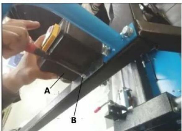
A-Power switch
B, C-Pan head screw
D-Plug.
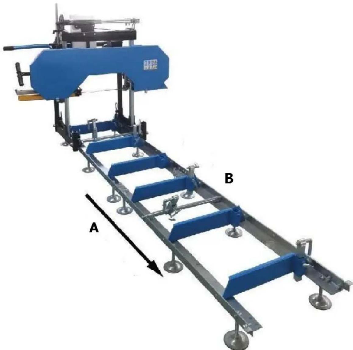
After carriage assembly on pallet, lift the machine carriage by forklift to make it stand up and put it onto the track system, ensure the grooves of four wheels well fit the rails of track and move smoothly on the track. If no forklift at working area, at least two peoples are necessary to make the machine carriage stand up and put it on the track.
A-Forklift
Push the machine carriage forward and back the track system to ensure that the width of the track allows for the saw head to move freely. If it binds, the "L" rails will need to be set further or closer together to achieve a consistent width along the entire track system. Once the desired width is achieved, all nuts and bolts can be tightened to the log bunks.
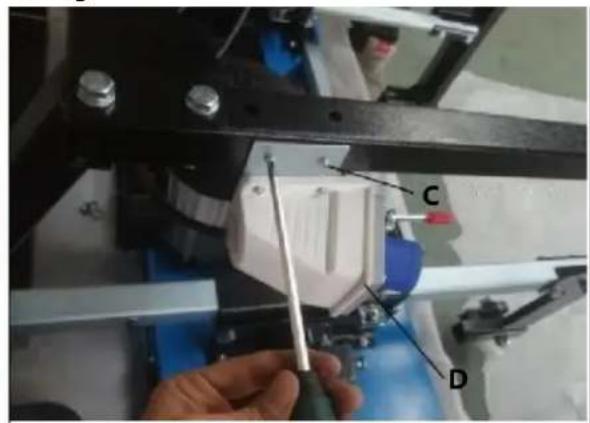
Assemble coolant system at back side of Joint bracket, please note that two bolts fixing Steel rope holder need to be reused, firstly only take off two nuts & washers and mount the Support post for tank and then tighten two nuts, must be careful during the time of assembly. And then put the plastic tank into the Support post, finally connect the water tube from Liquid tank to Spray mounted on the blade guide.
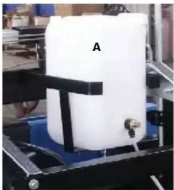
A - Liquid tank
B-Sprayer
Note: We recommend adding some dishwashing liquid to the tank to help lubricate the wood - two to three capfuls.
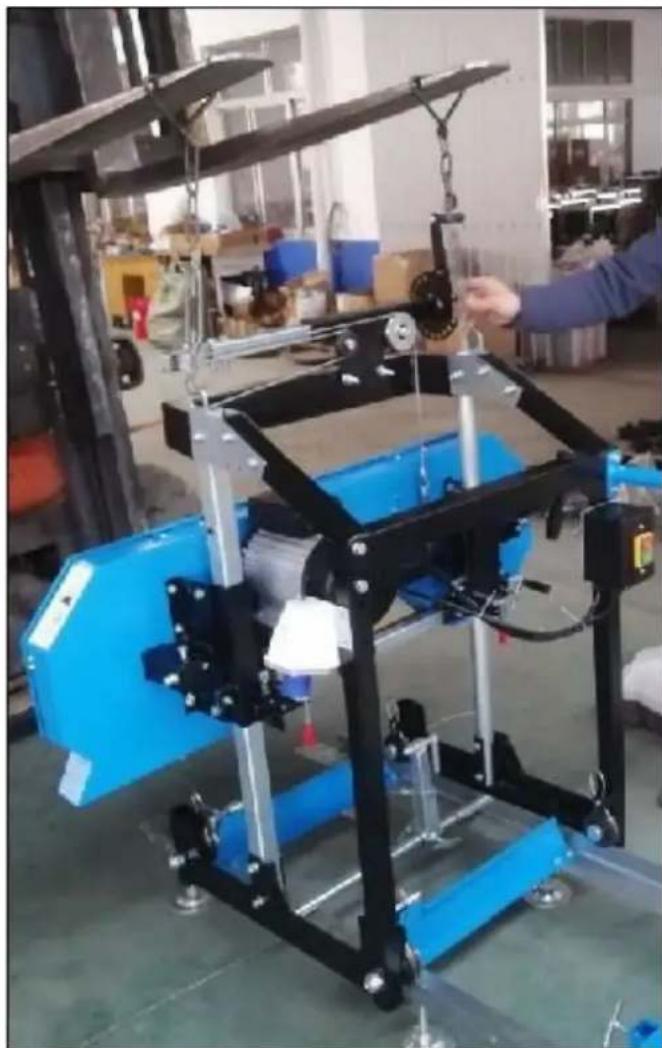
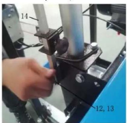
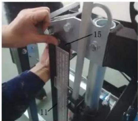
Find the Pointer complete (14) and Scale bracket (11), fix the Pointer complete at the right side of Sliding tube on the Saw head, use these parts supplied (12, 13). And fix the Scale bracket at the right side of Joint plate A, use the bolts and nuts (15). Finally tighten all the bolts.
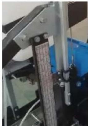
Using a tape measure, take a measurement at left and right side from the blade to the top of the cross arm. If there is no tape measure in the hand, one steel tube can be put onto the top side of the cross arm to check the distance at both sides. The distance should be equal at both sides. If it isn't equal, the height of left or right side of saw head can be adjusted by adjusting the tension of steel rope, and then turning the lift handle to make saw head lightly go up and down to get the balance at two sides. Finally the good parallel between saw blade and top surface of cross arm should be gotten.
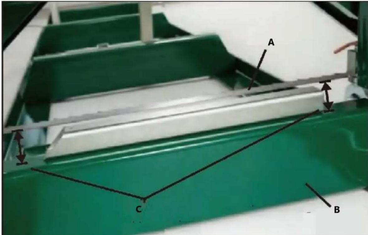
A-Sawblade
B-Cross arm
C-Check distance at two sides
A-Right side of the mill B-Left side of the mill
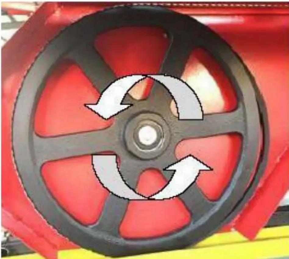
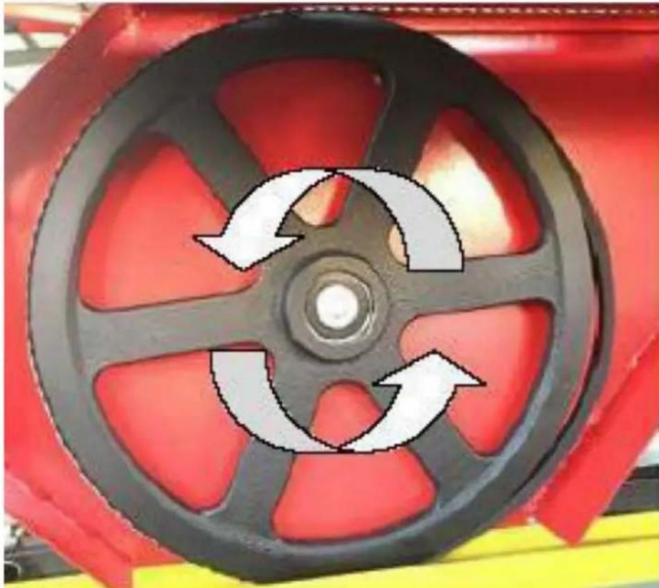
Notice:
Always cut in the direction shown above. The log clamp should always be at the right side of the log and the log supports should always be at the left. Failure to cut in this direction can cause the log to come lose and possibly even cause damage or injury.
Now that your sawmill is assembled, please run through the "SAWMILL SET-UP PROCEDURES" in the following section. Failure to do so may result in poor sawing performance, damage or injury.
SAWMILL SET-UP PROCEDURES
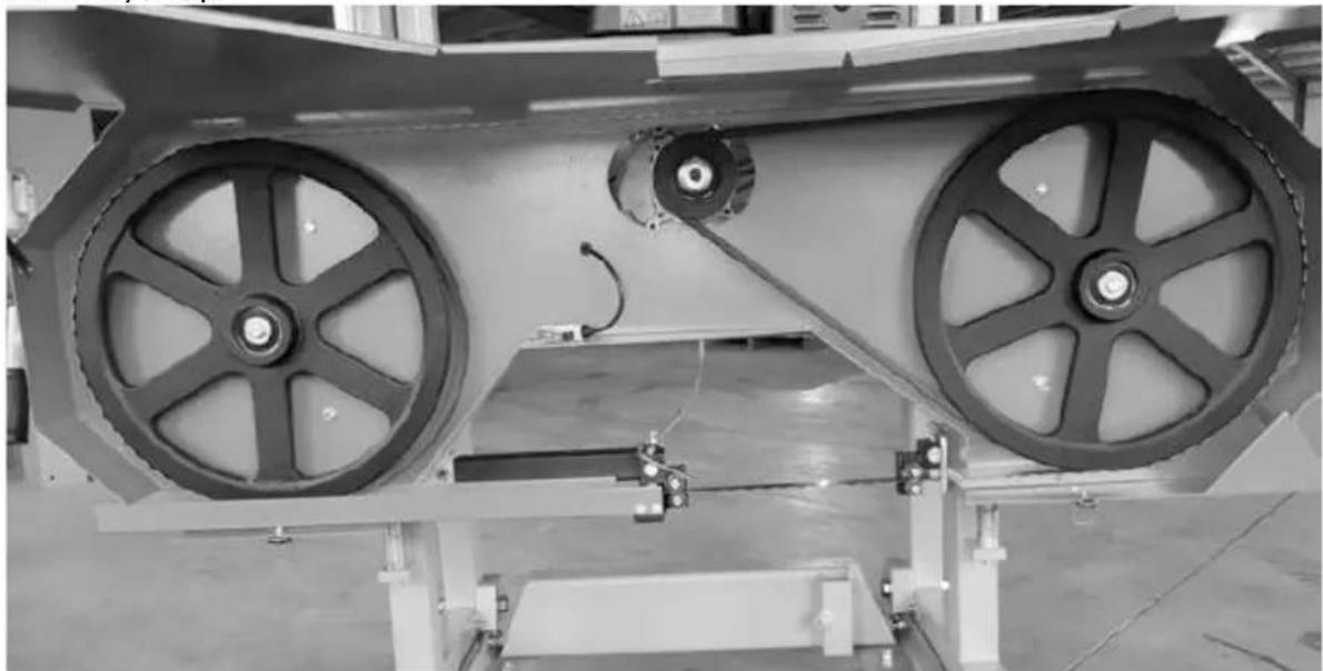
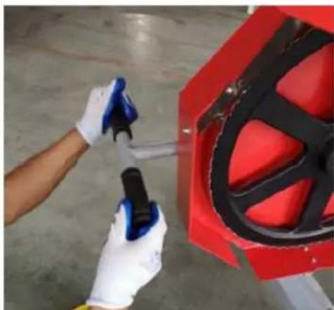
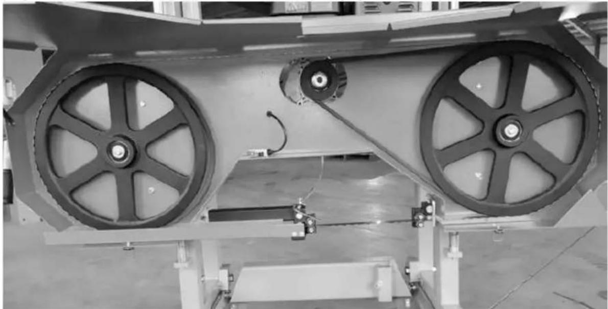
BELT TENSION
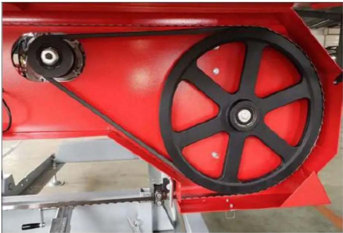
To check the belt tension, with your hand, firmly try to deflect the belt up and down. These should be no more than 1/4'' of deflection in both directions (1/2" total). If the belt deflects more than this, it will need to be tightened as described below.
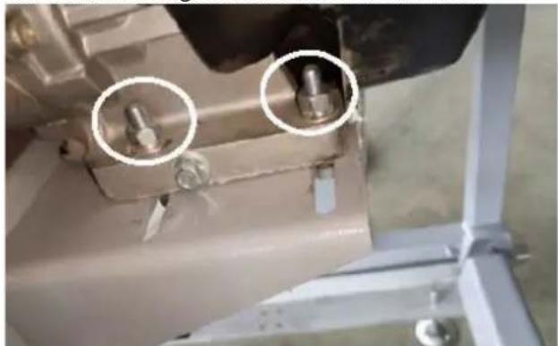
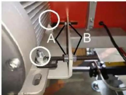
To change the drive side belt, loosen the four bolts that secure the engine to the engine mount using a 16mm wrench.
Now that the motor is free to slide on the motor mounting plate, turn the 13mm nut(A) on the horizontal stud in the anticlockwise direction, push the motor towards the stud and apply more tension on the belt. Do this step incrementally while checking the belt for proper deflection. It is also important to ensure that the motor remains perpendicular to the drive belt. Over tightening can cause the motor to twist on the mounting plate, resulting in belt alignment issues and premature wear. Once the desired belt tension is set, tighten the four engine bolts. Alternatively, if the drive belt is too tight, turn the 13mm nut(B) on the horizontal stud anticlockwise direction, push the motor away from the stud.
Never attempt the below action when the engine running. As a safety precaution, remove the spark plug cap. It is also advised to wear gloves and safety glasses when working with the blades as it is extremely sharp.

A - Rearward direction
B-Forward direction
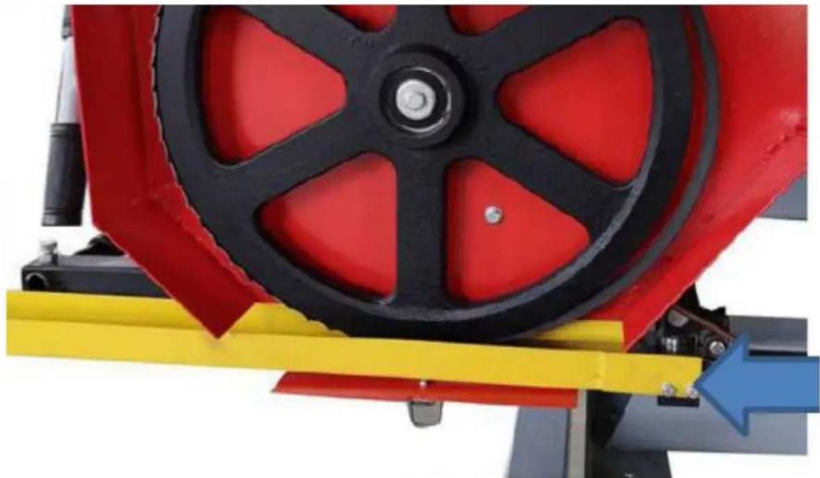
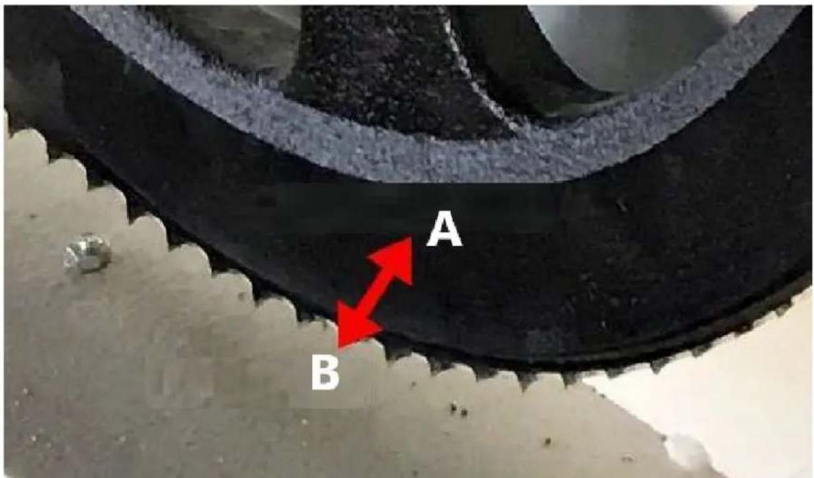
The blade should run with the same tooth to band wheel face distance on both sides. Measure the distance from the tip of the blade tooth to the front face of the band wheel on both sides. If an adjustment on either side is required, the below steps will detail this procedure.
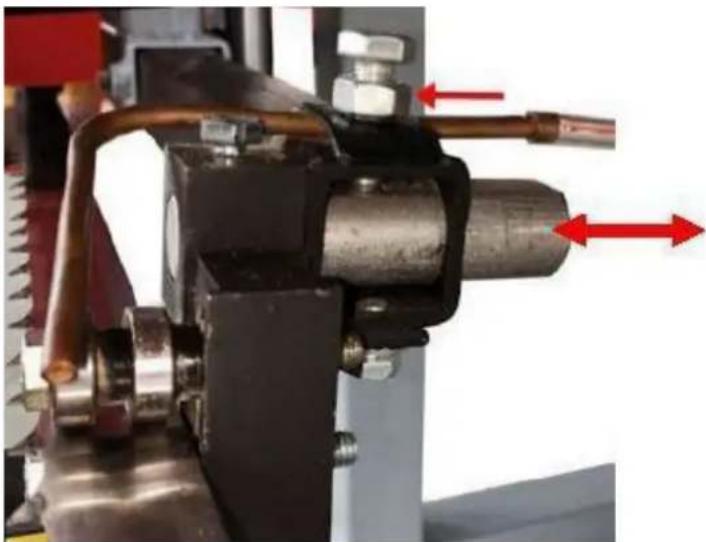
Loosen the blade guide assembly bolt with a 13mm socket. The round shaft should now be free to slide rearward and out of the way. Perform this step on both guide assemblies. This will ensure that the guide bearing do not influence tracking of the blade while adjusting.
Take some tension off of the blade by turning the "T" handle in the counter-clockwise direction one full turn from full tension position.
Adjusting The Right Hand Side

Loosen the tracking alignment bolt with an adjustable wrench. The alignment bolt can now be turned to change the angle of the band wheel and track the blade. To move the blade more rearward on the band wheel, this bolt will need to be turned clockwise. Alternatively, turning the bolt in the counterclockwise direction would force the blade to run more forward on the band wheel.

A - Rearward direction B-Forward direction
Wearing gloves, spin the band wheel with your hand and observe how the blade has changed tracking. Measure the distance again and repeat the above step to further compensate if required.
Adjusting The Left Hand Side
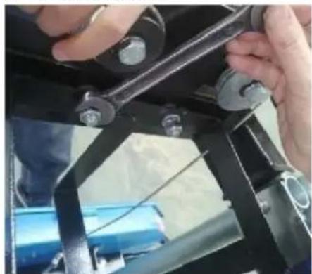
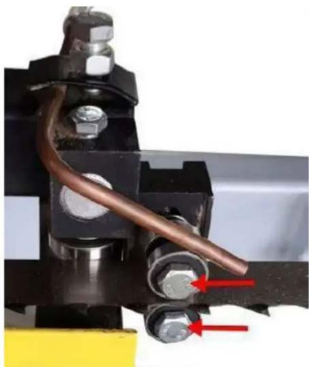
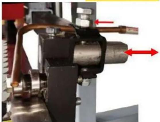
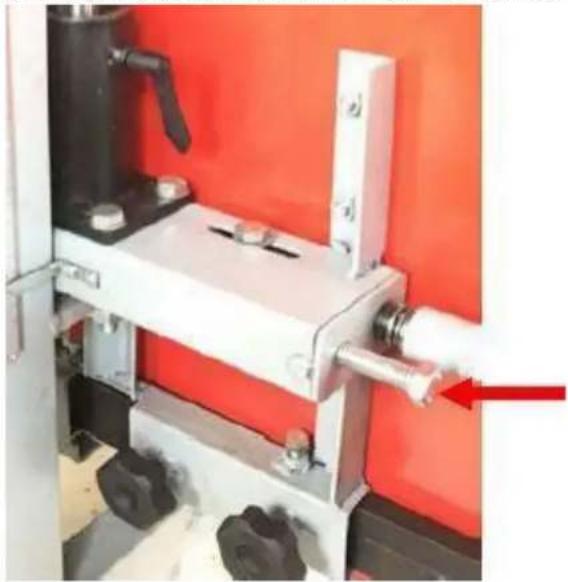
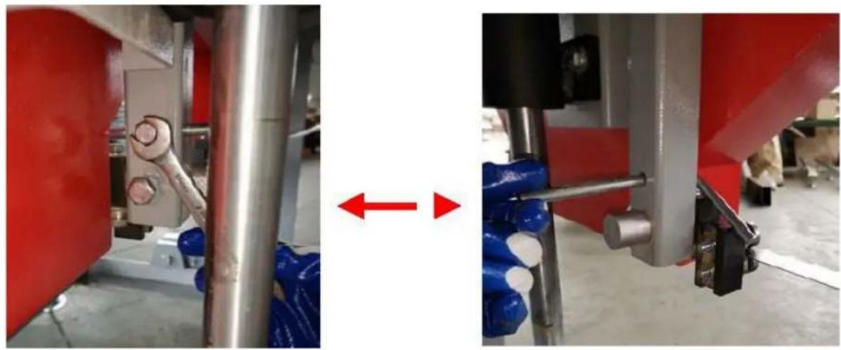
To adjust the left side of the sawmill, again start by taking the tension off of the blade by turning the "T" handle one turn in the counter-clockwise direction. Using a 16m wrench, loosen both "vertical bolts" a 1/2 turn. This will take the clamping force off of the band wheel shaft cause by these two bolts and allow it to move freely in the following steps.
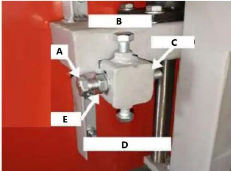
A-Horizontal bolt B-Vertical bolt C-Horizontal inside nut D-Bottom vertical bolt E-Horizontal outside nut
Moving The Blade Forward
Using a 16mm wrench, hold the "horizontal bolt" stationary with a wrench and turn the "horizontal inside nut" counter-clockwise a 1/2 turn. Still holding the "horizontal bolt" stationary, turn the "horizontal outside nut" clockwise a 1/2 turn. This has now shifted the "horizontal bolt" and band wheel shaft, causing the blade to track more forward.
Moving The Blade Rearward
Using a 16mm wrench, hold the "horizontal bolt" stationary with a wrench and turn the "horizontal outside nut" counter-clockwise a 1/2 turn. Still holding the "horizontal bolt" stationary, turn the "horizontal inside nut" clockwise a 1/2 turn. This step has now shifted the "horizontal bolt" and ban wheel shaft, causing the blade to track more forward. Tighten the vertical bolts, then nuts to clamp the band wheel shaft into the vertical position.

A - Rearward direction B-Forward direction
Re-tension the blade by turning the "T" handle a full turn in the clockwise direction. Wearing gloves, spin the ban wheel with your hand and observe how the blade has changed tracking. Measure the distance again and repeat the above step to further compensate if required. Once the blade is tracking true, bring the blade guide assemblies back up to the blade. Keep a paper width distance between the blade guide bearing and the back of the blade. More information on this set up can be found in the next section - "BLADE GUIDE ADJUSTMENT"
BLADE GUIDE ADJUSTMENT
Never attempt the below action when the engine running. As a safety precaution, remove the spark plug cap. It is also advised to confirm that the blade is tracking properly before performing the below. Blade tracking is covered in the previous page. Using a 13mm wrench loosen the blade guide bolt on both the left and right sides. They should be free to slide up and down.
Loosen the blade guide assembly bolt with a 13mm socket. The round shaft should now be free to slide back and forth. Position it so that there is a paper width gap between the bearing and the back of blade. Tighten bolt against the flat on the shaft to secure assembly back in position. Using a piece of paper in between the blade and blade guide blocks, tighten the bearing bolts.
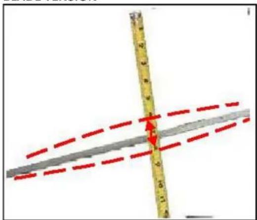
BLADE TENSION
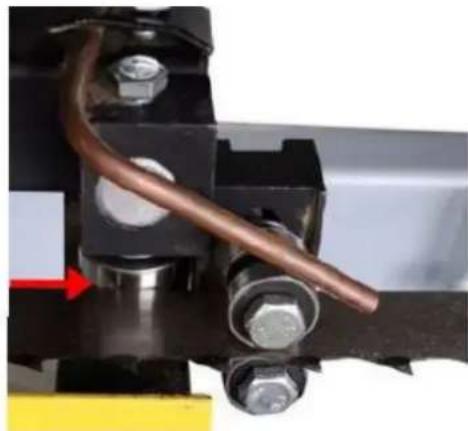
Proper blade tension is achieved when the blade deflects no more than a total of 1/8'' - 1/4'' up/down when it is firmly moved by hand at the centre location of the blade guide blocks. Turning the blade tension "T" handle in the clockwise direction will add tension to blade.
When tensioning the blade, make sure the tracking adjustment bolt sitting behind the "T" handle (pictured) is sitting back in its recess after you have finished and before the mill is run. Failure to do this will result in the blade being thrown and possibly broken.
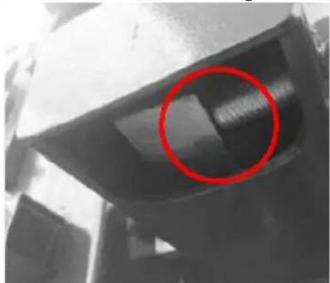
Tracking adjustment bolt out of recess, of it looks like this DO NOT start the mill until it is resting back in its recess.
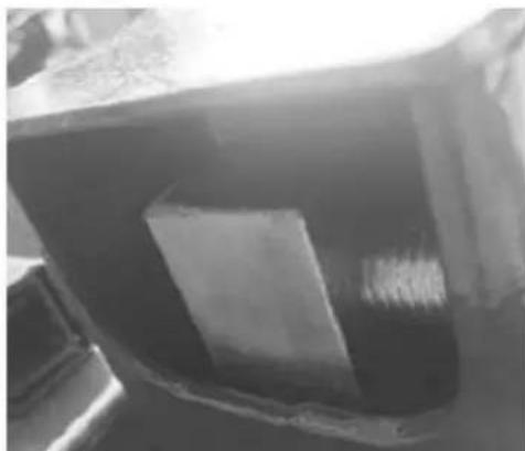
Tracking adjustment bolt sitting in recess. It should look like this before the mill is started back up.
Ensure the blade support arm is locked into place after tensioning the blade.
SAWMILL MAINTENANCE
CHANGING THE BLADE
Never attempt the below action when the engine running. As a safety precaution, remove the power plug. Gloves and safety glasses must be worn when changing blade.
Loosen the screw and pull back the blade limit lever.
Loosen the screw and pull out the blade guard cover.
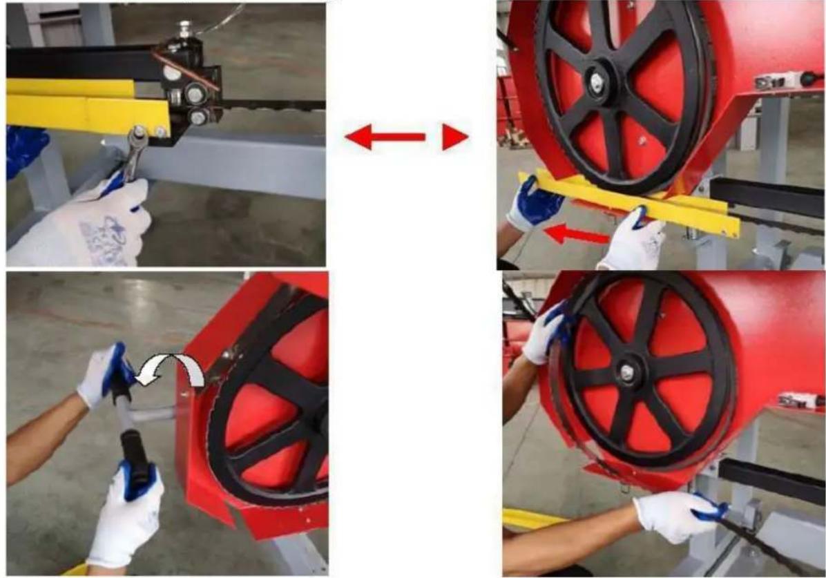
Remove the tension in the blade by turning the "T" handle in the counter-clockwise direction. The blade should now be loose and free to pull straight out the front. The new blade can now be installed, guards closed and proper blade tension set.
REPLACING BELTS
Never attempt the below action when the engine running. As a safety precaution, remove the power plug. Gloves and safety glasses must be worn when replacing the belts.
Replacement the belt need to remove the blade firstly, please follow above steps to remove the blade.
There are two rubber "V" belt on the sawmill and they should be replaced as a set. It is not advised to replace individual belts separately. It is recommended to use a BX50 cogged belt for the drive side and a BX41 follow belt.


To change the drive side belt, loosen the four bolts that secure the engine to the engine mount using a 16mm wrench.
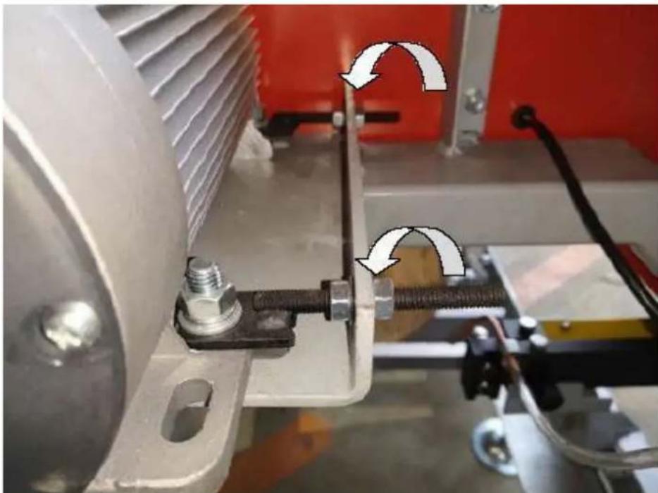
Now the motor is free to slide on the mounting plate, turn the 13mm nut on the horizontal stud in the counter-clockwise direction. This will allow the motor to move and will also take the tension off of the belt. The old belt can be removed and the new belt can be installed. Tension the new belt and refer to the BELT TENSION instructions described in the sawmill set up section of the manual. The follower belt can now be changed by simply pulling it off and installing the new one. The blade can now be re-installed, guards closed and proper blade tension set.
Note that blade tracking is likely to change and need adjusting when new belts are installed. Refer to "BLADE TRACKING" for more information.
Note - It is very important to take the tension off of the blade by turning the "T" handle in the counter-clockwise direction when the sawmill is not in use. Failure to do so, will result in flat spots on the rubber belts. These flat spots will cause the mill to vibrate excessively during next use.


A-Smerdozadub-Smervpred
V rukavicich otacejte pasyom kolem rukou a sledujte, jak se ostri zmenilo. Znovu zmezte vzdalenost a opakujte vyse uvedeny krok pro dalsi kompenzaci v pripadé potreby.
Uprava levé strany

A-Smerdozadub-Smervpred
Znovu napnete nuz otocenim rukojeti, T" o celou otacku ve smru hodinovych rucicek. V rukavicich otacejte rukou zakazovymoleckem a sledujte, jak cepel zmenila stopu. Znovu zmezte vzdalenost a opakujte vyse uvedeny krok pro dalsi kompenzaci v priade potreby. Jakmile kotouc spravne sleduje, privedte vodici sestavy kotouce zpetkotouci. Udrzujte vzdalenost sirky papiru mezi loziskem voditka cepele a zadni stranou cepele. Vice informaci o tomto nastaveni nalezete v dalsi casti - "NASTAVENI VODITKA BLADE"
SERIZENI VODITKA NOZE
A-Sunta taaksepain B-Sunta eteenpain

A-Sunta taaksepain B-Sunta eteenpain
GENERELL VEDLIKEHOLDSINFORMASJON

D-Bunn vertical bolt
A-Horisontal bolt
B - Vertical bolt
C-Horisontal innvendig mutter
E-Horisontal utvendig mutter