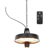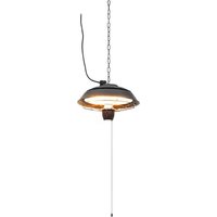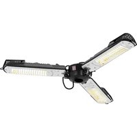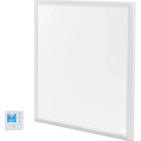
UNI_IHP_03 - Heating Uniprodo - Free user manual and instructions
Find the device manual for free UNI_IHP_03 Uniprodo in PDF.


User questions about UNI_IHP_03 Uniprodo
0 question about this device. Answer the ones you know or ask your own.
Ask a new question about this device
Download the instructions for your Heating in PDF format for free! Find your manual UNI_IHP_03 - Uniprodo and take your electronic device back in hand. On this page are published all the documents necessary for the use of your device. UNI_IHP_03 by Uniprodo.
USER MANUAL UNI_IHP_03 Uniprodo
text_image
Technical diagram showing various household appliances and fixtures with labeled parts A through GA: Heizgerät ×1
text_image
Diagram showing three different mechanical or electrical component configurations labeled D and B, with symbols indicating 'O' and a tool.natural_image
Technical diagram of a structural assembly with two labeled components (1 and 2), showing support structures and connection points (no text or symbols beyond labels)1 - Decke
natural_image
Pure mechanical diagram showing a shaft and housing assembly with rotating components (no text or symbols)This User Manual has been translated for your convenience using machine translation. Reasonable efforts have been made to provide an accurate translation; however, no automated translation is perfect nor is it intended to replace human translators. The official User Manual is the English version. Any discrepancies or differences created in the translation are not binding and have no legal effect for compliance or enforcement purposes. If any questions arise related to the accuracy of the information contained in the User Manual, please refer to the English version of those contents which is the official version.
Technical data
| Parameter description | Parameter value |
| Product name | Ceiling infrared panel with LED lighting |
| Model | UNI_IHP_03 |
| Rated voltage [V~] / frequency [Hz] | 230/50 |
| Rated power [W] | 400 |
| Protection rating IP | IP20 |
| Dimensions [width x depth x height; mm] | 630 x 660 x 35 |
| Weight [kg] | 4.4 |
1. General description
The user manual is designed to assist in the safe and trouble-free use of the device. The product is designed and manufactured in accordance with strict technical guidelines, using state-of-the-art technologies and components. Additionally, it is produced in compliance with the most stringent quality standards.
DO NOT USE THE DEVICE UNLESS YOU HAVE THOROUGHLY READ AND UNDERSTOOD THIS USER MANUAL.
To increase the product life of the device and to ensure trouble-free operation, use it in accordance with this user manual and regularly perform maintenance tasks. The technical data and specifications in this user manual are up to date. The manufacturer reserves the right to make changes associated with quality improvement. The device is designed to reduce noise emission risks to a minimum, taking into account technological progress and noise reduction opportunities.
Legend

text_image
CE Warning ! Water No House Construction NoThe product satisfies the relevant safety standards.
Read instructions before use.
The product must be recycled.
WARNING! or CAUTION! or REMEMBER! Applicable to the given situation. (general warning sign)
ATTENTION! Hot surface, risk of burns!
Only use indoors.
It is prohibited to place objects (such as towels, clothes etc.) above or directly in front of the device. In order to avoid overheating and fire hazards, the device must not be covered.
Do not spray with water.

PLEASE NOTE! Drawings in this manual are for illustration purposes only and in some details may differ from the actual product.
2. Usage safety

ATTENTION! Read all safety warnings and all instructions. Failure to follow the warnings and instructions may result in electric shock, fire and/or serious injury or even death.
The terms "device" or "product" are used in the warnings and instructions to refer to:
Ceiling infrared panel with LED lighting
2.1. Electrical safety
a) The plug must fit the socket. Do not modify the plug in any way. Using original plugs and matching sockets reduces the risk of electric shock.
b) Avoid touching earthed elements such as pipes, heaters, boilers and refrigerators. There is an increased risk of electric shock if the earthed device is exposed to rain, comes into direct contact with a wet surface or is operating in a damp environment. Water getting into the device increases the risk of damage to the device and of electric shock.
c) Do not touch the device with wet or damp hands.
d) Use the cable only for its designated use. Never use it to carry the device or to pull the plug out of a socket. Keep the cable away from heat sources, oil, sharp edges or moving parts. Damaged or tangled cables increase the risk of electric shock.
e) If using the device in a damp environment cannot be avoided, a residual current device (RCD) should be applied. The use of an RCD reduces the risk of electric shock.
f) Do not use the device if the power cord is damaged or shows obvious signs of wear. A damaged power cord should be replaced by a qualified electrician or the manufacturer's service centre.
g) To avoid electric shock, do not immerse the cord, plug or device in water or other liquids. Do not use the device on wet surfaces.
h) ATTENTION! DANGER TO LIFE! While cleaning, never immerse the device in water or other liquids.
i) Do not use in very humid environments or in the direct vicinity of water tanks.
j) Before the first use, please check whether the main voltage type and current comply with the indicated data on the type plate.
k) The device will draw more current than small devices, so a separate 10A socket is required.
I) Do not use the device when the socket or cord is overloaded.
m) Turn off the device and disconnect the power cord from the power outlet when the device is not in use.
n) Do not use this device near bathtubs, paddling pools, swimming pools or other containers with water. Risk of electric shock!
o) The device should be placed in a place where switches and regulators cannot be touched by a person in the bath or shower.
2.2. Safety in the workplace
a) Make sure the workplace is clean and well lit. A messy or poorly lit workplace may lead to accidents. Try to think ahead, observe what is going on and use common sense when working with the device.
b) Do not use the device in a potentially explosive environment, for example in the presence of flammable liquids, gases or dust.
c) If you are unsure about whether the product is operating correctly or if you find damage, please contact the manufacturer's service centre.
d) Only the manufacturer's service centre may make repairs to the product. Do not attempt to make repairs yourself!
e) In case of fire, use a powder or carbon dioxide (CO2) fire extinguisher (one intended for use on live electrical devices) to put it out.
f) Please keep this manual available for future reference. If this device is passed on to a third party, the manual must be passed on with it.
g) Keep packaging elements and small assembly parts in a place not available to children.

Remember! When using the device, protect children and other bystanders.
2.3. Personal safety
a) Do not use the device when tired, ill or under the influence of alcohol, narcotics or medication which can significantly impair the ability to operate the device.
b) The device is not designed to be handled by persons (including children) with limited mental and sensory functions or persons lacking relevant experience and/or knowledge unless they are supervised by a person responsible for their safety or they have received instruction on how to operate the device.
c) The device is not a toy. Children must be supervised to ensure that they do not play with the device.
d) Do not put your hands or other items inside the device while it is in use!
2.4. Safe device use
a) Do not overload the device. Use the appropriate tools for the given task. A correctly-selected device will perform the task for which it was designed better and in a safer manner.
b) Do not use the device if the "ON/OFF" switch does not function properly (does not switch the device on and off). Devices which cannot be switched on and off using the ON/OFF switch are hazardous, should not be operated and must be repaired.
c) Make sure the plug is disconnected from the socket before attempting any adjustments, accessory replacements or before putting the device aside. Such precautions will reduce the risk of accidentally activating the device.
d) When not in use, store in a safe place, away from children and people not familiar with the device who have not read the user manual. The device may pose a hazard in the hands of inexperienced users.
e) Keep the device in perfect technical condition.
f) Keep the device out of the reach of children.
g) Device repair or maintenance should be carried out by qualified persons, only using original spare parts. This will ensure safe use.
h) To ensure the operational integrity of the device, do not remove factory-fitted guards and do not loosen any screws.
i) Do not move, adjust or rotate the device in the course of work.
j) Clean the device regularly to prevent stubborn grime from accumulating.
k) The device is not a toy. Cleaning and maintenance may not be carried out by children without supervision by an adult person.
I) Keep the device away from sources of fire and heat.
m) Panels intended for wall mounting only must not be mounted to the ceiling. Panels intended for mounting only to the ceiling should not be mounted on the wall. Otherwise, it may cause overheating or even fire.
n) Temperature sensors or a temperature controller should not be placed directly in the space towards which the heating panel will be facing, as this will affect the temperature measurement.
o) Do not use the device in small rooms where there are people who cannot leave the room on their own and who are not under constant supervision.
p) Some parts of this product can become very hot and cause burns. Do not touch the surface of the device during its operation and for some time after switching it off until it has cooled down.
q) Do not install the device near flammable materials. Danger of fire.
r) In order to avoid burns, special attention should be paid to places where people requiring special treatment are present: infants and children, people with sensitive skin, the elderly, the sick, people who are intoxicated, people taking sleeping pills.
s) Remove all protective films (front and back) before use.
t) Do not use the device in a humid environment.
u) Do not sit on the device.
v) The appliance should be installed at a sufficient distance from walls and other objects (especially curtains and similar flammable/heat-sensitive items).
w) Do not place the device on a flammable surface.
x) Never drill into the device.
y) Allow the device to cool down before transporting and/or carrying out maintenance work.
z) In order to avoid overheating and fire hazards, the device must not be covered.
aa) The wall panels must be installed at least 0.6 m above the floor.
bb) Ceiling panels must be installed at least 1.8 m above the floor.

ATTENTION! Despite the safe design of the device and its protective features, and despite the use of additional elements protecting the operator, there is still a slight risk of accident or injury when using the device. Stay alert and use common sense when using the device.
3. Use guidelines
The device is designed to provide an efficient, comfortable and healthy heating system for any domestic users. The user is liable for any damage resulting from unintended use of the device.
3.1. Device description
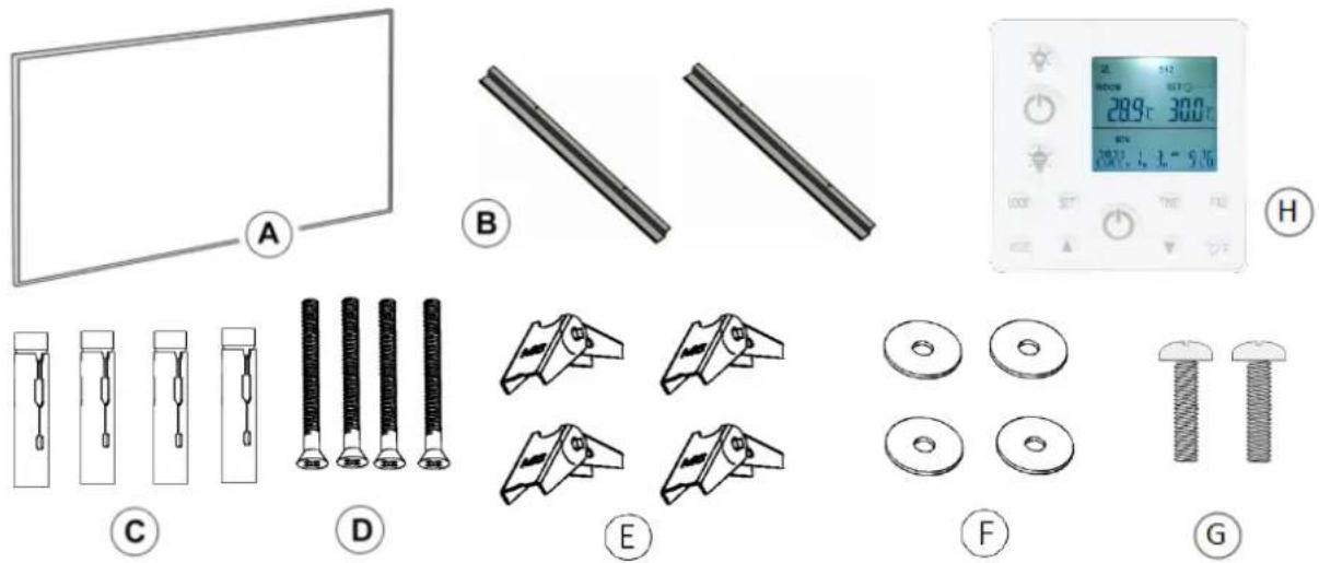
text_image
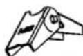
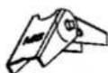
Technical diagram showing various household appliances and fixtures with labeled parts A through H, including a digital display and various mechanical components.A: Heating Device ×1
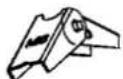
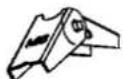
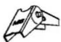
B: Hanging Units × 2
C: Metal Expansion Tubes × 4
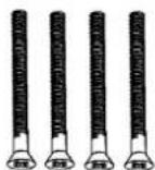
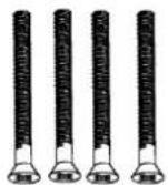
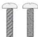
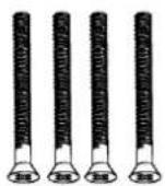
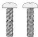
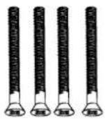
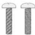
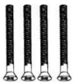
D: Screws × 4
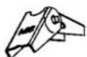
E: Spring Toggles × 4
F: Washers × 4
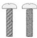
G: Screws × 2
H: Thermostat × 1
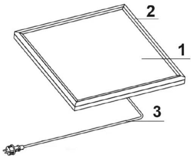
text_image
1 2 31 - Front surface
2 - LED light
3 - Power cord
3.2. Assembling the device

• Installation work must be carried out by a professional electrician!
• Do not suspend the panels by the power cable!
- Do not use any protruding parts to hang or suspend the brackets!
• Make sure the ceiling is sufficiently stable!
- Remove the front protective film before use!
• The power supply cable must be well earthed!
- ATTENTION! Use wall plugs suitable for the type of ceiling material on which the unit will be mounted.
- Before starting the installation, please make sure to determine the material of the ceiling. The following are the installation methods for concrete ceilings and gypsum board ceilings. Please choose and use appropriate accessories based on the specific situation.
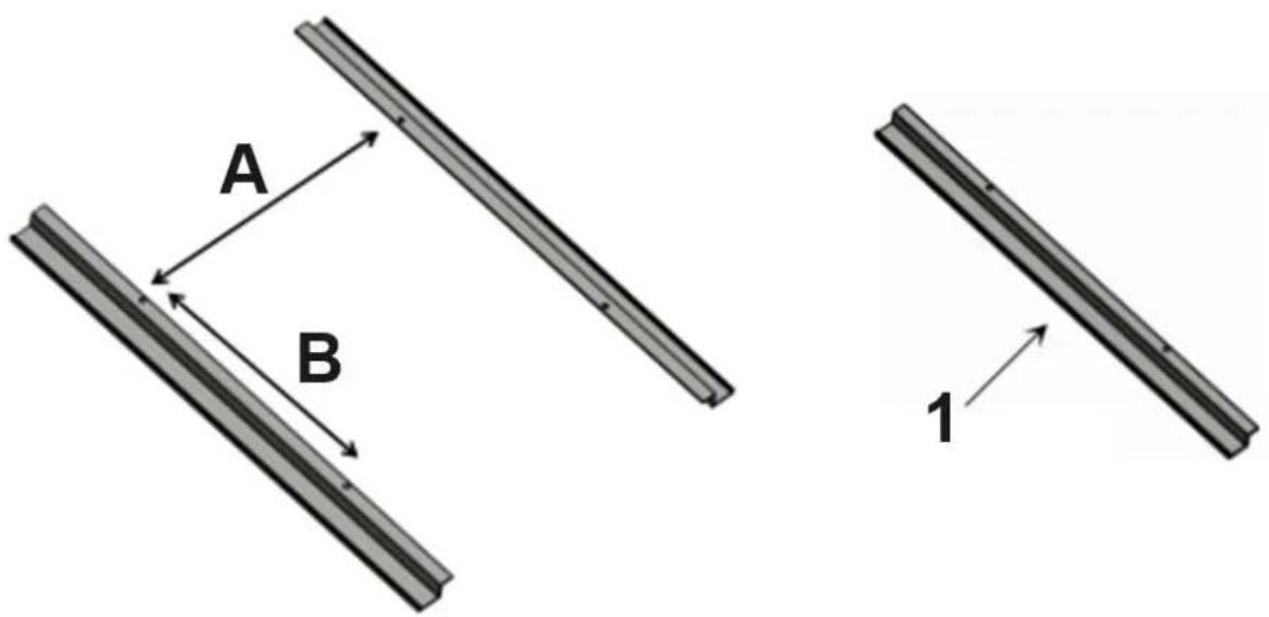
- Drill four holes on the ceiling with correct distance A and distance B.
text_image
A B 1A = 495 mm
B = 100 mm
1 - Hook
a. Concrete ceiling Installation
Step1: Measure and mark the correct distances "a" and "b" on the concrete ceiling where you want to install.
Step2: Drill four 10mm holes at the marked positions.

Excessive drilling diameter is strictly prohibited!
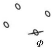
Step3: Insert the metal expansion tubes(C) into the drilled holes.

text_image
Diagram illustrating three different mechanical or electrical component configurations labeled D and B, with symbols indicating parts of a valve or connector.Step4: Thread screws(D) through the hanging units(B) holes, then tighten them into the tubes.

Turn the screws to the end tightly, This is very IMPORTANT!

natural_image
Technical diagram of a structural assembly with two labeled components (1 and 2), showing support structures and connection points (no text or symbols beyond labels)1 - Ceiling 2 - Firmly screwed to the end
b. Gypsum Board Ceiling Installation:
Step1: Measure and mark the correct distances "a" and "b" on the concrete ceiling where you want to install.

Please note that the spring toggles(E) are designed for gypsum boards or wooden ceilings with a thickness ranging from 9-18mm. It is forbidden to be used on gypsum board ceilings with a thicknesses less than 9mm.
For wooden ceilings exceeding 18mm in thickness, consider employing metal expansion tubes(C) or using your own carpentry nails, ensuring the carpentry nails meet or exceed M5*40mm in size.
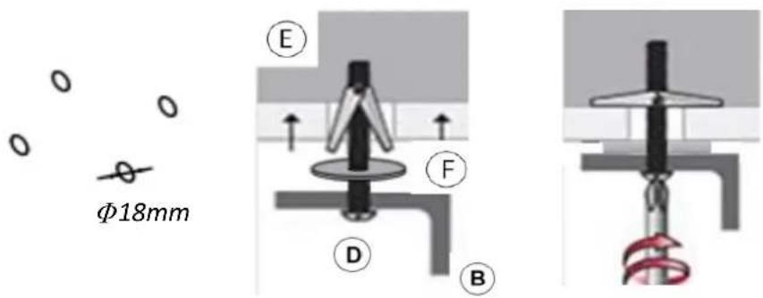
Step 2: Drill four 18mm holes at the marked positions.

Excessive drilling diameter is strictly prohibited!
Step 3: Thread screws(D) through the hanging units(B) holes, washers(F) and spring toggles(E), and then insert the spring toggles(E) into the pre-drilled holes
text_image
φ18mm E F D BStep4: Tighten the screws.
Install the Heating Device (A) after completing installation of a or b
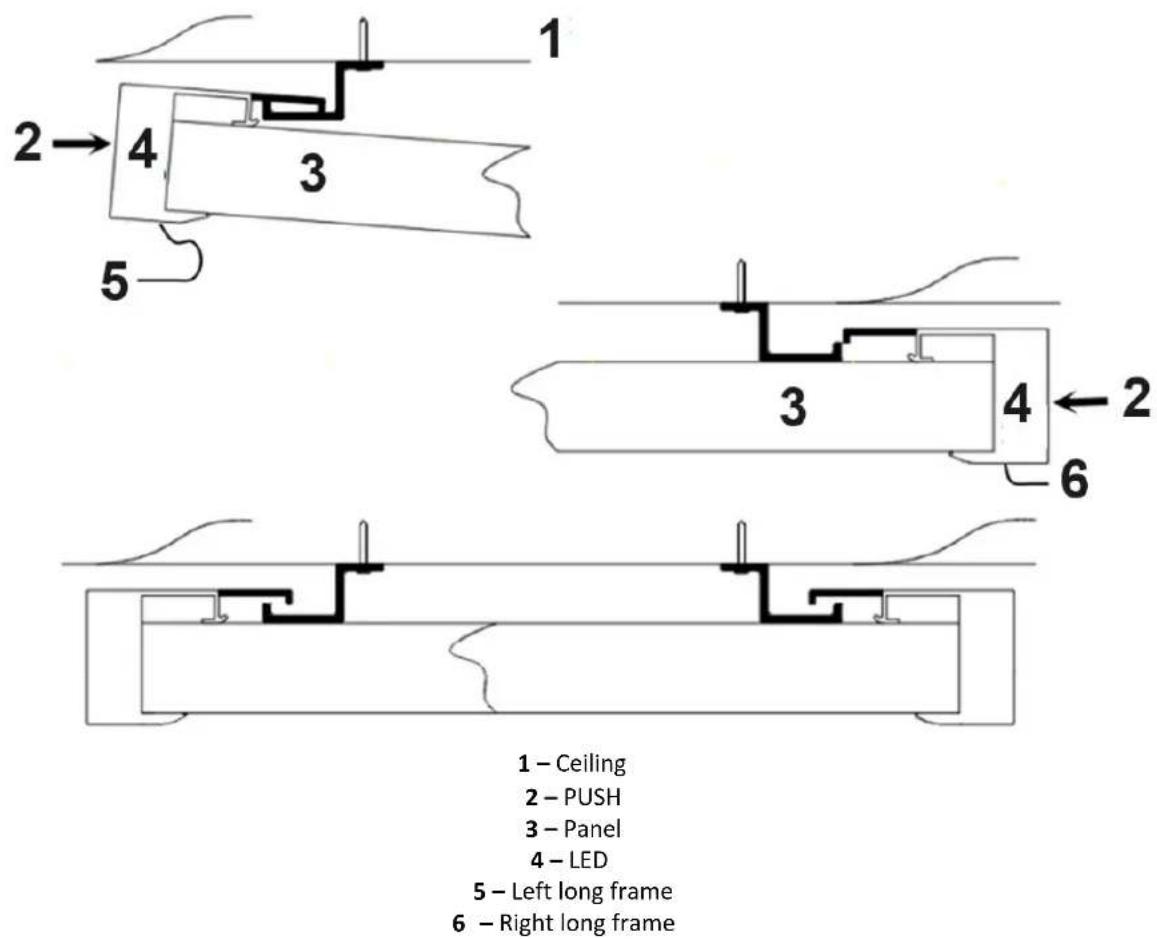
- Push the back of the left long frame into the hook, then push the back of the right long frame into the second hook.
Note: The hooks are only for the two long frames, not the two short frames!
text_image
1 2 → 4 3 5 3 4 ← 2 6 1 – Ceiling 2 – PUSH 3 – Panel 4 – LED 5 – Left long frame 6 – Right long frame- Screw the screws(G) into the holes reserved on both sides of the product and tighten.

natural_image
Pure mechanical diagram showing a shaft and housing with rotating components (no text or symbols)3.3. Device use
3.3.1. Thermostat
Specification:
• Battery-powered: DC 4 x 1.5V AAA batteries (not included)
- Set temperature range: 0^ 45^ , resolution: 1^
• Room temperature range: 0°C \~ 50°C, display resolution: 0.1°C
• Accuracy of the measured temperature: ±0.5°C
• Working environment range 1°C \~ 50°C
• Radio frequency 433.92MHz
Description:

text_image
1 ROOM 5+2 SET 22.5°C 45.0°C SAT 2023 Y I_M I_D 0:34 4 LOCK 6 SET 9 TIME FAV 11 5 MODE 7 8 10 C/F 121 - Brightness enhancement
2 - Light ON/OFF
3 – Brightness reduction
4 - Lock button
5 - Mode button
6 - Set button
7 - Value increase button
8 - Power ON/OFF
9 - Time set button
10 - Value decrease button
11 - FAV button
12 - Temperature unit change button
- This thermostat also includes individual operation part for LED light.
- The thermostat acquires the room temperature with its integrated sensor and transmit signal to the panel to turn on/off heating as the ambient temperature changing, in order to maintain a constant room temperature. When the ROOM temperature is 0.5^ C higher than the SET temperature, thermostat will send OFF commands to panel; When the ROOM temperature is 0.5^ C lower than the SET temperature, thermostat will send ON commands to panel to turn on heating function.
- The screen display shows the setting temperature as well as the measured temperature, time, date, modes etc.
- The thermostat has week programmable, temperature setting, auto-off when temperature jump, favorite temperature, time setting functions etc.
- It is powered by 4pcs of 1.5V AAA batteries. Please change with new ones if the battery symbol gets flashing, or else it will not be able to control the panel.
- Keypad locking function is designed to prevent the children from misusing.
- LCD screen powered off means only the panel heating power off, the remote control itself is still under working state until batteries dead/out or broken.
- The LCD screen only can work in temperature range from 1°C \~ 50°C.
Operation
- Power on the panel, press ON/OFF for thermostat, then press button °C/°F and MODE buttons at same time to pair the thermostat and panel until long beep sound.
NOTE:
1) Pairing should be finished within 1 minute, or else you need to re-power on the panel.
2) Please re-power on the panel if you want to pair the panel with another thermostat.
3) One thermostat can be paired to and work with several panels at same time.
4) Before pairing please do power off those panels which you don't want to pair.
- Press ON/Off button for LED light to turn on/off the LED light surrounding the panel, and long press to switch light color (for some models only).
- Press +/- to adjust the brightness, short press can adjust brightness to 100%, 75%, 50% and 25%, long press can adjust from 100% to 5%.
- Press ON/Off button for thermostat to turn on/off the heating power.
- Long press LOCK 3 seconds to lock/unlock the buttons.
- Press °C/°F button to convert the temperature display measurement unit.
- Long press TIME 3 seconds to set year, month, date and time with UP and DOWN buttons.
- Press UP and DOWN to set target temperature.
Even during week timer on period, users can also press UP and DOWN to set a temporary temperature which will convert to week target temperature at the time when next TIMER ON start to work.
- Press and hold FAV for 3 seconds until the set temperature icon flashes, press UP and DOWN to set a favorite temperature, short press FAV to confirm.
- Press the MODE and TIME buttons simultaneously to select 5+2 or 1...7 programming modes.
- Press and hold the MODE buttons for 3 seconds to turn the programming mode on or off, ON means open, OFF means close.
- Press and hold the SET button for 3-5 seconds to enter into programming mode. Note: Programming mode has a time-out limit whereby if no buttons are pressed within 3-5 seconds, it reverts back to the main screen.
1) 5+2 Programming Mode
You can program the thermostat to fit your lifestyle — week and weekend, plus up to 4 groups of time interval per day.
Step 1. Once in 5+2 mode, Press and hold the SET button for 3-5 seconds until Program icon ① and MON TUE WED THU FRI is displayed with ON and Time Icon flashing on screen.
Step 2. Press ▲ button to adjust hour(+1hour/press) and press ▼ to adjust Minute(+5minutes/press) to set the starting time of Program ①.
Step 3. Press the SET button once and OFF icon flashing on screen, Use ▲ Button to adjust hour(+1hour/press) and press ▼ to adjust minute (+5minutes/press) to set the ending time of Program ①.
Step 4. Press the SET button once again and set temperature icon flashing on screen, Use ▲ or ▼ button to set the desired temperature to be maintained for program ①.
Step 5. Press the SET button to bring up Program ② of week days, repeat Steps 2-5. And users can set up Program ③ and ④ in similar manner.
Step 6. After finishing setting Program ④, press the SET button to bring up SAT and SUN setting, repeat steps 2-5 to set Program①②③④ of weekends.
2) 1-7 Programming Mode
You can program the thermostat everyday with setting 2 groups of time interval per day.
Once in 1-7 Mode, Press and hold the SET button for 3-5 seconds until Program icon ① and MON is displayed with ON and Time icon flashing on screen, users can follow the above step 2-4 to set On/Off time and desired temperature of Program ① and ② from Monday to Sunday in sequence.
Tips:
1) The default starting time is 00:00, the ending time is 00:00, and the default operating temperature is 15 degrees.
2) If the user does not adjust the default On/Off time of 00:00, the programming settings is invalid.
3) Running time of Program ①②③④ should not be overlapped, and the ending time value of each program must be later than the starting time, otherwise setting is invalid.
4) In 5+2 mode, if you do not want to set a mid-day heating period(Program ② or ③), simply set the programs ② or ③ to a lower temperature than default with very short intervals. An example is shown below.
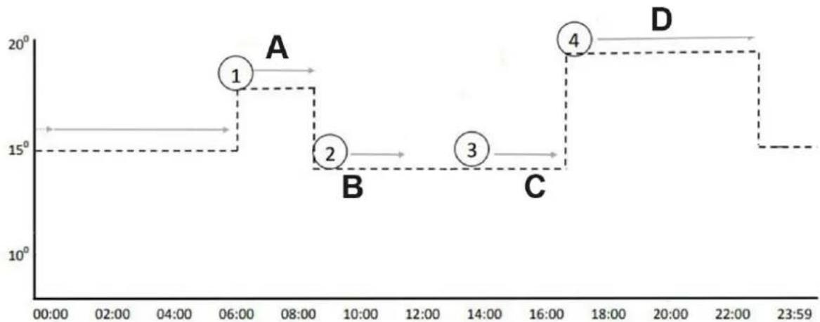
line
| Time | Value | | :--- | :--- | | 06:00 | 18 | | 08:00 | 15 | | 10:00 | 14 | | 14:00 | 14 | | 16:00 | 20 | | 23:59 | 15 |4 time / temperature programs applied over a 24 hour period
A – Morning heating 18° until 08:30
B – Daytime set-back 14° until 12:00
C – Daytime set-back 14° until 17:00
D – Afternoon / early evening heating 20° until 23:30
5) The programmed time / temperature setting will be restored with the next program entry in the memory.
6) Once finish setting up the programming mode, the thermostat will work under programming mode ON even if the thermostat is turned off. The heating device will be switched ON or OFF according to the programming setting.
7) Programming groups allow running across dates.
8) When programming, please don't set overlapped intervals between workgroups. If the time periods overlaps, the group with an earlier starting time will be executed ON first, and the group with an earlier ending time will be executed OFF, until the next group turns ON.
- The thermostat will automatically turn off the heating device if a sudden drop in temperature in the room is detected.
- Press FAV, set temperature will convert to favorite temperature, and it will convert again to week target temperature at the time when TIMER ON start to work.
-
The symbol means heating, it only displays when room temperature is 0.5^ C (or more) lower than set temperature.
-
The backlight will be ON when press any button in the state of power-on.
Remarks
- All settings need to be re-set after battery replacement.
- Alkaline battery is recommended. If ALL buttons on the thermostat are not working, try replacing the batteries.
- Please do change the batteries with new ones once the screen battery symbol gets flashing, or else it may result in halted/stuck/not working.
- Check if set temperature is higher enough than room temperature first if the heating can not be turned on by thermostat.
- If users want the week timer and temperature work, make sure the TIMER function has been switched to ON by long press MODE setting; If users want it not working, switch the TIMER to OFF.
- Do not cover or touch the temperature sensor which is at the top of the thermostat.
- Do put the thermostat in a open normal room environment rather not inside a drawer/pocket or under pillow/quilt etc.
- Please do take out the batteries from the thermostat if long time no use.
3.4. Cleaning and maintenance
a) Always unplug the device before cleaning or putting it away.
b) Use only non-corrosive cleaners to clean the surface.
c) After cleaning the device, all parts should be dried completely before using it again.
d) Store the unit in a dry, cool place, free from moisture and direct exposure to sunlight.
e) Do not spray the device with a water jet or submerge it in water.
f) The device must be regularly inspected to check its technical efficiency and spot any damage.
g) Do not leave the battery in the device if it will not be used for a longer period of time.
h) Use a soft, damp cloth for cleaning.
i) Do not use sharp and/or metal objects for cleaning (e.g. a wire brush or a metal spatula) because they may damage the surface material of the appliance.
j) Do not clean the device with an acidic substance, agents of medical purposes, thinners, fuel, oils or other chemical substances because it may damage the device.
SAFE REMOVAL OF BATTERIES AND RECHARGEABLE BATTERIES:
The batteries are installed in the devices.
Remove used batteries from the device using the same procedure by which you installed them.
Recycle batteries with the appropriate organisation or company.
DISPOSING OF USED DEVICES:
Do not dispose of this device in municipal waste systems. Hand it over to an electric and electrical device recycling and collection point. Check the symbol on the product, instruction manual and packaging. The plastics used to construct the device can be recycled in accordance with their markings. By choosing to recycle you are making a significant contribution to the protection of our environment.
Contact local authorities for information on your local recycling facility.

natural_image
Simple rectangular frame with a circular label containing the letter 'A' at the bottom (no text or symbols inside)
natural_image
Two identical cylindrical metal rods arranged side by side (no text or symbols visible)
text_image
209℃ 300℃ 2022.1.1 - 5.26 H





text_image
Diagram showing three different mechanical or electrical component configurations labeled D and B, with symbols indicating parts of a valve or actuator.natural_image
Technical diagram of a structural assembly with two labeled components (1 and 2), showing bolted connections and support structures (no text or symbols beyond labels)natural_image
Pure mechanical diagram showing a shaft and housing assembly with rotating components (no text or symbols)text_image
CE ! Water No. 10000000000000000000000000000000000000000000000000000000000000000000000000000000000000000000000000000text_image
Technical diagram showing various household appliances and fixtures with labeled parts A through Htext_image
Diagram showing three different mechanical or electrical component configurations labeled D and B, with symbols indicating 'O' and a tool.natural_image
Pure mechanical diagram showing a shaft and housing assembly with rotating components (no text or symbols)text_image
CE ! No Bar Housetext_image
Technical diagram showing various mechanical components and a digital control panel with temperature reading.text_image
Diagram showing three different mechanical or electrical component configurations labeled D and B, with symbols indicating 'O' and a tool.natural_image
Technical diagram of a structural assembly with two labeled components (1 and 2), showing support structures and arrows indicating direction (no text or symbols beyond labels)natural_image
Pure mechanical diagram showing a shaft and housing assembly with rotating components (no text or symbols)natural_image
Simple rectangular frame with a circular symbol labeled 'A' at the bottom center (no text or numbers inside)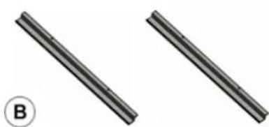
natural_image
Two parallel cylindrical rods with a circled number B, no text or symbols present
text_image
28.9°C 30.0°C BUT 28.2, 4.3" 5.26





text_image
Diagram illustrating three different mechanical or electrical component configurations labeled D and B, with symbols indicating parts of a valve or connector.natural_image
Technical diagram of a structural assembly with two labeled components (1 and 2), showing support posts and internal components (no text or symbols beyond labels)natural_image
Pure mechanical diagram showing a shaft and housing with rotating components (no text or symbols)text_image
Product catalog image showing various household appliances and accessories with labeled parts A through H.text_image
Diagram illustrating three different mechanical or electrical component configurations labeled D and B, with symbols indicating parts of a valve or connector.natural_image
Technical diagram of a structural assembly with two labeled components (1 and 2), showing support structures and connection points (no text or symbols beyond labels)natural_image
Pure mechanical diagram showing a shaft and housing assembly with rotating components (no text or symbols)natural_image
Simple rectangular frame with a circular symbol labeled 'A' at the bottom (no text or numbers inside)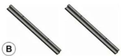
natural_image
Two parallel cylindrical rods with a labeled circle (B) at the bottom left, no text or symbols on the rods themselves.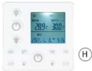
text_image
温度 28.9°C 30.0°C MEN 28.7°C 3.4" 5.30" 100K SET THE TIN 2/3 H




text_image
Diagram showing three different mechanical or electrical component configurations labeled D and B, with symbols indicating 'O' and a tool.natural_image
Technical diagram of a structural assembly with two labeled components (1 and 2), showing support structures and connection points (no text or symbols beyond labels)1 - mennyezet
natural_image
Pure mechanical diagram showing a shaft and housing with rotating components (no text or symbols)text_image
CE Warning ! Water drop No House Construction Nonatural_image
Simple rectangular frame with a circular symbol labeled 'A' at the bottom (no text or numbers inside)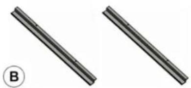
natural_image
Two parallel cylindrical rods with a labeled circle (B) in the bottom-left corner, no text or symbols on the rods themselves.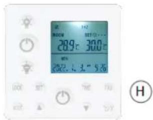
text_image
28.9°C 30.0°C H









A: Varmeenhed ×1
B: Hængeenheder × 2
text_image
Diagram showing three different mechanical or electrical component configurations labeled D and B, with symbols indicating 'O' and a tool.natural_image
Technical diagram of a structural assembly with labeled components (1 and 2), showing no readable text or symbols beyond labels.natural_image
Pure mechanical diagram showing a shaft and housing with rotating components (no text or symbols)3.3. Brug af enhed
3.3.1. Termostat
Specifikation:
natural_image
Simple rectangular frame with a circular symbol labeled 'A' at the bottom (no text or numbers inside)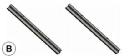
natural_image
Two parallel cylindrical rods with a labeled circle (B) at the bottom left, no text or symbols on the rods themselves.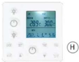
text_image
28.9°C 30.0°C H






text_image
Diagram illustrating three different mechanical or electrical component configurations labeled D and B, with symbols indicating parts of a valve or connector.natural_image
Technical diagram of a structural assembly with two labeled components (1 and 2), showing support structures and connection points (no text or symbols beyond labels)natural_image
Pure mechanical diagram showing a shaft and housing with rotating components (no text or symbols)text_image
Technical diagram showing various household appliances and fixtures with labeled parts A through GA: Verwarmingsapparaat × 1
text_image
Diagram illustrating three different mechanical or electrical component configurations labeled D and B, with symbols indicating parts of a valve or connector.natural_image
Technical diagram of a structural assembly with two labeled components (1 and 2), showing bolted connections and support structures (no text or symbols beyond labels)OBS! Varm overflate, fare for forbrenning!
text_image
Technical diagram showing various household appliances and fixtures with labeled parts A through GA: Oppvarmingsenhet × 1
B: Hengende enheter × 2
text_image
Diagram illustrating three different mechanical or electrical component configurations labeled D and B, with symbols indicating parts of a valve or connector.natural_image
Technical diagram of a structural assembly with two labeled components (1 and 2), showing bolted connections and support structures (no text or symbols beyond labels)1 - Tak 2 - Skrudd fast til enden
natural_image
Pure mechanical diagram showing a shaft and housing assembly with rotating components (no text or symbols)text_image
Technical diagram showing various household appliances and fixtures with labeled parts A through GA: Värmeenhet × 1
B: Hängande enheter × 2
text_image
Diagram illustrating three different mechanical or electrical component configurations labeled D and B, with symbols indicating parts of a valve or connector.natural_image
Technical diagram of a structural assembly with two labeled components (1 and 2), showing bolted connections and support structures (no text or symbols beyond labels)natural_image
Pure mechanical diagram showing a shaft and housing assembly with no text, numbers, or symbolstext_image
Technical diagram showing various household appliances and fixtures with labeled parts A through H, including a display screen and mechanical parts.text_image
Diagram showing three different mechanical or electrical component configurations labeled D and B, with symbols indicating 'O' and a tool.natural_image
Technical diagram of a structural assembly with two labeled components (1 and 2), showing support posts and internal components (no text or symbols beyond labels)natural_image
Pure mechanical diagram showing a shaft and housing assembly with rotating components (no text or symbols)For the disposal of the device please consider and act according to the national and local rules and regulations.
CONTACT
expondo Polska sp. z o.o. sp. k.