
KFMV 17-15 F - Milling machine METABO - Free user manual and instructions
Find the device manual for free KFMV 17-15 F METABO in PDF.

| Product type | Chamfering router (flush trim router) |
| Brand | Metabo |
| Model | KFMV 17-15 F |
| Supply voltage | 230 V ~ (estimate) |
| Frequency | 50/60 Hz |
| Power input | 1700 W (estimate) |
| No-load speed range | 6200 - 12,000 rpm (6 positions) |
| Machinable materials | Steel, stainless steel, aluminum, aluminum alloys |
| Adjustable chamfer angle | Yes, via graduated scale (17) |
| Chamfer height per pass (max at 45°) | 9 mm |
| Weight (without cable) | 5.5 kg (estimate) |
| Handles | Bow handle (1) + removable side handle (5) |
| Electronic system | VTC (speed control under load), overload protection |
| Protection | Protection class II (double insulation) |
| Safety device | Restart protection, RCD protection switch recommended |
| Maintenance and cleaning | Regularly clean ventilation slots, replace indexable inserts |
| Repairability | Repairs by an electrician, spare parts available via Metabo |
| Accessories | Carbide indexable inserts, fixing screws, etc. |
| Intended use | Edge milling on metals, professional use |
Frequently Asked Questions - KFMV 17-15 F METABO
User questions about KFMV 17-15 F METABO
0 question about this device. Answer the ones you know or ask your own.
Ask a new question about this device
Download the instructions for your Milling machine in PDF format for free! Find your manual KFMV 17-15 F - METABO and take your electronic device back in hand. On this page are published all the documents necessary for the use of your device. KFMV 17-15 F by METABO.
USER MANUAL KFMV 17-15 F METABO
natural_image
Illustration of a power tool with a circular dial and adjustable grip, mounted on a base (no text or symbols visible)
 | KFMV 17-15 F*1) Serial Number: 01770500.. | KFMV 17-15 F*1) Serial Number: 01770610.. | |
| n min | -1 (rpm) | 6200 - 12000 | 6200 - 12000 |
| P1 | W | 1700 1400 | |
| P2 | W | 880 740 | |
| hmax(45°) | mm (in) | 15 (19/32) 15 | (19/32) |
| hmax(30°) | mm (in) | 20 (25/32) 20 | (25/32) |
| bmax(45°) | mm (in) | 21 (13/16) 21 | (13/16) |
| a° | 0 - 90° 0 - 90° | ||
| dmin | mm (in) | 100 (315/16) | 100 (315/16) |
| m kg (lbs) | 6,3 (13.9) 6,3 | (13.9) | |
| ah/Kh | m/s2 | < 5 / 1,5 < 5 | / 1,5 |
| LpA/KpA | dB(A) | 97 / 3 97 / 3 | |
| LWA/KWA | dB(A) | 105 / 3 105 / 3 | |

*2) 2014/30/EU, 2006/42/EC, 2011/65/EU
*3) EN 62841-1:2015, EN ISO 12100:2010, EN IEC 63000:2018
2024-03-14, Bernd Fleischmann
Aluminium, Kupfer, Messing....4-6
natural_image
Two 3D mechanical parts labeled A and B, showing different surface profiles (no text or symbols beyond labels)natural_image
3D rendered mechanical component with a square base and central cavity (no text or symbols)Original instructions
1. Declaration of Conformity
We, being solely responsible: Hereby declare that these bevellers, identified by type and serial number *1), meet the requirements of all relevant directives *2) and standards *3). Technical documents for *4) - see page 4.
2. Specified Conditions of Use
The beveller is intended for the milling of edges of steel, stainless steel, aluminium and aluminium alloys in the professional sector.
The user bears sole responsibility for any damage caused by inappropriate use.
Generally accepted accident prevention regulations and the enclosed safety information must be observed.
3. General Safety Information

For your own protection and for the protection of your power tool, pay attention to all parts of the text that are marked with this symbol!

WARNING – Read the operating instructions to reduce the risk of injury.

WARNING – Read all safety warnings, instructions, illustrations and
specifications provided with this power tool. Failure to follow all instructions listed below may result in electric shock, fire and/or serious injury.
Save all warnings and instructions for future reference.
Always include these documents when passing on your power tool.
4. Special Safety Instructions
a) Hold the power tool by insulated gripping surfaces only, because the cutter may contact its own cord. Contact with a "live" wire will also make exposed metal parts of the power tool "live" and could give the operator an electric shock.
b) Use clamps or another practical way to secure and support the workpiece to a stable platform. Holding the workpiece by hand or against your body leaves it unstable and may lead to loss of control.
c) Do not use accessories which are not specifically designed and recommended by the tool manufacturer. Just because the accessory can be attached to your power tool, it does not assure safe operation.
d) Do not use any damaged accessories. Before use, check the indexable inserts for chipping, cracks or signs of severe wear and tear. If power tool or accessory is dropped,
inspect for damage or install an undamaged accessory.
e) Wear personal protective equipment. Depending on application, use face shield, safety goggles or safety glasses. As appropriate, wear a dust mask, hearing protectors, gloves and a workshop apron capable of stopping small abrasive or workpiece fragments. The eye protection must be capable of stopping flying debris generated by various applications. The dust mask or respirator must be capable of filtrating particles generated by the particular application. Prolonged exposure to high intensity noise may cause hearing loss.
f) Keep bystanders a safe distance away from your work area. Anyone entering the work area must wear personal protective equipment.
Fragments of workpiece or of a broken accessory may fly away and cause injury beyond immediate area of operation.
g) Always hold the tool firmly in your hand(s) during start-up. The reaction torque of the motor, as it accelerates to full speed, can cause the tool to twist.
h) Use clamps or another practical way to secure and support the workpiece to a stable platform. Never hold a small workpiece in one hand and the tool in the other hand while in use. Clamping a small workpiece allows you to use your hand(s) to control the tool.
i) Never lay the power tool down until the accessory has come to a complete stop. The spinning accessory may grab the surface and pull the power tool out of your control.
j) Do not run the power tool while carrying it at your side. Accidental contact with a rotating accessory could snag your clothing, pulling the accessory into your body.
k) Regularly clean the power tool's air vents. The motor's fan will draw the dust inside the housing and excessive accumulation of powdered metal may cause electrical hazards.
I) Do not use the power tool in the vicinity of flammable materials. Sparks and hot chips can ignite these materials.
m) Do not use accessories that require liquid coolants. Using water or other liquid coolants may result in electrocution or shock.
4.1 Kickback and related warnings
Kickback is the sudden response to an accessory pinching or jamming while rotating. Pinching or snagging causes rapid stalling of the rotating accessory. Pinching or snagging causes rapid stalling of the rotating accessory which in turn causes the uncontrolled power tool to be forced in the direction opposite of the accessory's rotation at the point of the binding.
For example, if an indexable insert is snagged or pinched by the workpiece, the edge of the insert that is entering into the pinch point can dig into the
ENGLISHen
surface of the material causing the insert to climb out or kick out. The indexable insert may either jump towards or away from the operator depending on direction of the indexable insert holder at the point of pinching. Indexable inserts may also break under these conditions.
Kickback is the result of power tool misuse and/or incorrect operating procedures or conditions and can be avoided by taking proper precautions as given below.
a) Maintain a firm grip on the power tool and position your body and arm to allow you to resist kickback forces. The operator can control kickback forces, if proper precautions are taken.
b) Use special care when working corners, sharp edges etc. Avoid bouncing and snagging the accessory. Corners, sharp edges or bouncing have a tendency to snag the rotating accessory and cause loss of control or kickback.
c) Always feed the accessory into the material in the same direction as the cutting edge is exiting from the material (which is the same direction as the chips are thrown). Feeding the tool in the wrong direction causes the cutting edge of the bit to climb out of the work and pull the tool in the direction of this feed.
d) Prevent any jamming of the indexing insert or excessive pressure. Do not set the chamfer height greater than the permitted maximum. Overstressing the indexable insert increases the loading and susceptibility to twisting or binding of the disc in the cut and the possibility of kickback or breakage of the indexable insert.
e) Do not position your hand in line with and behind the indexable insert. When the indexable insert is moving away from your body at the point of operation, the possible kickback may propel the rotating indexable insert and the power tool directly at you.
Turn/replace blunt indexable inserts or inserts where the coating is worn in due time. Blunt indexable inserts increase the risk of the machine getting jammed and breaking.
4.2 Additional Safety Instructions:
Hold the power tool by the insulated gripping surfaces because the milling cutter may hit its own cord. Contact with a "live" wire will also make exposed metal parts of the power tool "live" and could give the operator an electric shock.
Keep work area clean and well lit. Cluttered or dark areas invite accidents.

WARNING – Always wear protective goggles.

Wear ear protectors.

Wear suitable work clothes.

Ensure that nobody gets injured by catapulted foreign bodies.

Keep persons nearby and pets at a safe distance to the device.

Keep away hair, loose clothing, fingers and other body parts. They can get caught and sucked in. Use a hair net for long hair.

Warning of rotating tools

Pull the plug out of the socket before making any adjustments, changing tools, carrying out maintenance or cleaning.

WARNING – Always operate the power tool with two hands.

Danger of crushing and injury from sharp edges. Wear protective gloves.
Indexable inserts, holders for indexable inserts, the workpiece and chips can be hot after work. Wear protective gloves.
Wear ear protectors when working for long periods of time. High noise levels over a prolonged period of time may affect your hearing.
Use only sharp, undamaged indexable blades.
The workpiece must lay flat and be secured against slipping, e.g. using clamps. Large workpieces must be sufficiently supported.
Ensure that sparks produced during work do not constitute a risk to the user or others and are not able to ignite flammable substances. Areas at risk must be protected with flame-resistant covers. Always keep a fire extinguisher on hand when working in areas prone to fire risk.
Always hold the machine with both hands on the designated handles, take a secure stance and concentrate on the work.
Keep your hands away from the milling area and from the tool.
Do not touch the rotating accessory! Remove chips and similar material only with the machine at a standstill.
Damaged, eccentric or vibrating tools must not be used.
Sufficiently tighten the screws of the guide rail angle setting and also the screws of the guide plates.
Do not work overhead.
Persons who are not familiar with the operating instructions must not use the device. Children should be supervised to ensure that they do not play with the device.
The device must not be used or stored outside in wet conditions.
Reducing dust exposure:
WARNING - Some dust created by power sanding, sawing, grinding, drilling, and other construction activities contains chemicals known to cause cancer, birth defects or other reproductive harm. Some examples of these chemicals are:
- Lead from lead-based paints,
- crystalline silica from bricks and cement and other masonry products, and
- arsenic and chromium from chemically treated lumber.
Your risk from these exposures varies, depending on how often you do this type of work. To reduce your exposure to these chemicals, work in a well-ventilated area, and work with approved safety equipment, such as those dust masks that are specially designed to filter out microscopic particles.
This also applies to dust from other materials, such as some timber types (like oak or beech dust), metals, asbestos. Other known diseases are e.g. allergic reactions, respiratory diseases. Do not let dust enter the body.
Observe the relevant guidelines and national regulations for your material, staff, application and place of application (e.g. occupational health and safety regulations, disposal).
Collect the particles generated at the source, avoid deposits in the surrounding area.
Use suitable accessories for special work. In this way, fewer particles enter the environment in an uncontrolled manner.
Use a suitable extraction unit.
Reduce dust exposure with the following measures:
- do not direct the escaping particles and the exhaust air stream towards yourself or nearby persons or towards dust deposits,
- use an extraction unit and/or an air purifier,
- ensure good ventilation of the workplace and keep it clean using a vacuum cleaner. Sweeping or blowing stirs up dust.
- Vacuum or wash protective clothing. Do not blow, beat or brush protective gear.
4.3 Special safety instructions for mains powered machines:
Pull the plug out of the socket before making any adjustments, changing tools, carrying out maintenance or cleaning.
Use of a fixed extractor system is recommended. Always install an RCD with a maximum trip current of 30 mA upstream. When the machine is shut down by the RCD, it must be checked and cleaned. See chapter 10. Cleaning.
5. Overview
See pages 2 and 3.
1 Bow handle
2 Locking discs
3 Thumb screws
4 Threaded holes on gear housing
5 Side handle *
6 Scale (chamfer height)
7 Adjusting ring (chamfer height)
8 Clamping screws on scale ring
9 Scale ring (chamfer height)
10 Handle
11 Chip protection plate screws
12 Chip protection plates
13 Base plate
14 Arrow = prescribed working direction
15 Speed adjustment wheel
16 Electronic signal indicator
17 Scale (chamfer angle)
18 Screws (chamfer angle)
19 Indexable insert holder / milling head
20 Indexable insert
21 Fastening screw for indexable insert
22 Trigger switch
23 Guide roller
24 Scale (pipe diameter)
6. Initial Operation
Before commissioning, check that the rated mains voltage and mains frequency stated on the type plate match your power supply.
Always install an RCD with a maximum trip current of 30 mA upstream.
6.1 Attaching the additional handle
Only work with a bow handle (1) or Metabo side handle (5) fitted! Attach the handle as shown (see page 2, Fig. A).
Attach bow handle (1)
- Fit locking discs (2) to the left and right of the handle (1).
- Move the handle (1) with the locking discs (2) from the front to the gear housing.
- Insert the thumb screws (3) to the left and right of the handle (1) and turn gently.
- Adjust the handle (1) to the required angle.
- Firmly tighten the thumb screws (3) to the left and right manually.
Fitting the side handle (5)
When milling edges of small angles (setting < 30°) depending on the working conditions, it may be advantageous to use a side handle (5) rather than the bow handle (1).
- Attach the side handle (5) on the right or left side of the machine and secure. All Metabo side handles with M8 thread can be used for this purpose.
7. Setting
Pull the plug out of the socket before making any adjustments, changing tools, carrying out maintenance or cleaning.
Indexable inserts, holders for indexable inserts, the workpiece and chips can be hot after work. Wear protective gloves.
7.1 Setting the chamfer angle
- Read the set angle on the scale (17).
- Loosen the screws (11) and slide both chip protection plates (12) (on the left and right of the machine) upwards.
ENGLISHen
- Loosen the screws (18) (front and back) and set the chamfer angle to the desired angle by turning the base plate (13). Read the set chamfer angle on the scale (17).
- Firmly tighten the screws (18) (front and back).
- Slide both chip protection plates (12) (on the left and right of the machine) all the way down. Tighten the screws (11) (on the left and right of the machine).
- Changing the chamfer angle also changes the chamfer height (due to the design). Therefore, also set the chamfer height again every time you adjust the chamfer angle. See chapter 7.2
7.2 Setting the chamfer height
Set the chamfer angle first:
- First check that the desired chamfer angle is set: read the set chamfer angle on the scale (17). Adjust if necessary. See chapter 7.1
Determining the setting value:
Note: always produce large chamfer heights in several milling operations (at least 3). Hard materials require more milling operations. This has the following advantages: a higher indexable insert service life, work results with a higher surface quality, more pleasant working conditions.

Do not exceed the "maximum chamfer height per milling operation" specified below.
Example. at 45^
1st milling operation: max. 9 mm
2nd +3rd milling operation: max. 3 mm
Do not exceed the maximum permitted chamfer height ( h_max ) (see the Technical Specifications chapter).
It is recommended that very little material is removed during the last milling operation to ensure an optimum surface quality.
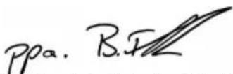
- Select the line that applies to the set chamfer angle (see diagram on the back)
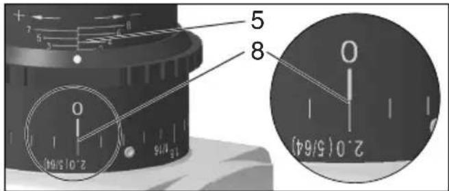
- Example for a chamfer angle of 45^ and a desired chamfer height of 3 mm (see figure below). Result: setting value = 2.0.
line
| x | h (mm) | | ---- | ------ | | 0 | 0 | | 2.0 | 3 |Select the chamfer height that you want to set on the Y-axis. Draw a horizontal line to the intersection with the line. Draw a vertical line from this intersection to the X-axis. Read the
value on the X-axis. You must now set this "X" value as follows on the machine.
Note: The diagram is based on sharp-edged workpieces. For workpieces with rounded edges, the milling height must be taken into account during setting.
Setting the chamfer height:
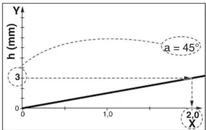
- Pull the adjusting ring (7) upwards and turn it so that the "X" value from the diagram is set on the scale (9). See figure (below): set "X" value = 2.0. (One revolution corresponds to "X" = 3. For large X values: perform several revolutions. The scale (6) is used for rough orientation during the setting process).
- Carry out a trial cut.
- Proceed as follows if the chamfer height should be set very accurately for the last milling operation: Carry out a trial cut. Measure the cut chamfer height and adjust it by one scale mark if necessary by turning the adjusting ring (7): clockwise rotation = larger chamfer height. Anti-clockwise rotation = lower chamfer height. Carry out another trial cut. Repeat this step if necessary.
8. Use
8.1 Switching on and off

Always guide the machine with both hands.

Switch on first, then guide the accessory towards the workpiece.

Avoid inadvertent starts: always switch the tool off when the plug is removed from the socket or if there has been a power cut.

In continuous operation, the machine continues running if it is forced out of your s. Therefore, always hold the machine with hands using the handles provided, stand rely and concentrate.

Avoid the machine swirling up or taking in dust and chips. After switching off the machine,
only place it down when the motor has come to a standstill.
Torque activation (see page 3, fig. B):
Switching on: Slide the trigger switch (22) forwards and then push the trigger switch (22) upwards.
Switching off: Release the trigger switch (22).
Continuous operation:
Switching on: Switch the machine on as described above. Now slide the trigger switch (22) forwards again and release in the front position to lock the trigger switch (22) (continuous operation).
Switching off: Push the trigger switch (22) upwards and release.
8.2 Setting speed
The speed can be preset via the thumb-wheel (15) and is infinitely variable.
Positions 1-6 correspond approximately to the following no-load speeds:
1....6200 / min 4 .... 9,600 / min
2.....7,100 / min 5 .....11,100 / min
3.....8,300 / min 6 .....12,000 / min
The VTC electronics make material-compatible work possible and an almost constant speed, even under load.
Speed recommendations for different materials:
Aluminium, copper, brass 4-6
Steel up to 400 N/mm ^2 .....4-6
Steel up to 600 N/mm ^2 ......3-5
Steel up to 900 N/mm ^2 .....2-4
Stainless steel....1-3
The best way to determine the ideal setting is through a practical trial.
8.3 General working instructions
- Check the indexable inserts (20). Change damaged or worn indexable inserts.
- Fix workpiece without vibrations using clamping devices.
-
Pay attention to chapter 8.4 when working on pipes.
-
Set the chamfer angle (see chapter 7.1).
-
Set the chamfer height (see chapter 7.2).
-
Always hold the machine with both hands on the designated handles, take a secure stance and concentrate on the work.
-
The indexable inserts (20) do not touch the workpiece. First switch on, then place the machine with the base plate (13) onto the workpiece and only then put the accessory close to the workpiece.
-
Slide the machine only in the direction specified by an arrow on the machine (14).
Slide the machine only in the direction of the arrow (14). Otherwise there is the risk of kickback. Guide the machine evenly at a speed suitable for the material being processed.
Do not tilt, apply excessive force or sway from side to side.
- Guide the machine in such a way that the base plate (13) is in contact with the workpiece.
- Finishing the work: remove the tool from the workpiece, switch off machine. Let motor come to a stop, put down machine.
8.4 Working on the outer edge of pipes
- Determine the diameter of the pipe to be worked on.
- See page 3, fig. C: Attach the guide roller (23) to the base plate (13) as shown. Move the guide roller (23) and adjust on the scale (24) on the pipe diameter. Tighten the guide roller nut with a spanner and thus tighten the guide roller.
- Pay attention to the general working instructions (chapter 8.3).
- Always hold the machine with both hands on the designated handles, take a secure stance and concentrate on the work.
- Place the machine with the guide roller (23) on the outer surface of the pipe. Then place the base plate on the surface of the pipe end.
- The indexable inserts (20) do not yet touch the workpiece. First switch on, then slowly tilt the machine around the guide roller (23) to move the milling head close to the workpiece.
- Pay attention to the general working instructions (chapter 8.3).
8.5 Possibility to turn the base plate (13)
If you prefer to install the base plate (13) in a longitudinal manner, the Metabo customer service will provide you with conversion instructions on request if these are not included in the package. Information can also be found at www.metabo.com.
9. Maintenance
9.1 Changing indexable inserts
Pull the plug out of the socket before making any adjustments, changing tools, carrying out maintenance or cleaning.
Indexable inserts, holders for indexable inserts, the workpiece and chips can be hot after work. Wear protective gloves.
Regularly check the indexable insert holder (19). Repair/replace damaged or worn indexable insert holders.
Regularly check all indexable inserts (20). Change damaged or worn indexable inserts.
Turn/replace blunt indexable inserts or inserts where the coating is worn in due time. Blunt indexable inserts increase the risk that the machine will catch and breaks loose or that the indexable insert plate holder (19) is damaged.
Do not use heavily worn or defective indexable insert plates.
Always turn or replace all indexable inserts.
Use only indexable inserts approved by Metabo. See the Accessories chapter.
ENGLISHen
natural_image
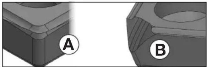
Two 3D mechanical components labeled A and B, showing different surfaces and angles (no text or symbols beyond labels)Figure A: Normal wear: turn / replace indexable insert.
Figure B: Wear after working on hard materials: turn / replace turning plate. In the event of heavier wear, do not use the indexable insert plate and instead replace.
- Loosen the screws (11) and slide one chip protection plate (12) upwards.
- Turn the indexable insert holder (19) manually if necessary.
- Unscrew the fastening screw (21) and remove the indexable insert (20).
- Clean indexable insert (20) and clamping surfaces on the indexable insert holder (19).
- Turn the indexable insert or replace the indexable insert if all blades are blunt.
- Fix again the indexable insert (20) with a fastening screw (21). Torque: 3.5 Nm.
- Slide the chip protection plate (12) all the way down. Tighten the screws (11).
Note: Causes for indexable inserts with broken corners or, in extreme cases, for broken indexable inserts, can include:

natural_image
3D rendered mechanical component with a V-shaped groove and a central circular recess (no text or symbols)- Impacts on the indexable insert due to incorrect use: See chapter 8.3.
- Workpiece vibrations: Fix workpiece without vibrations using clamping devices.
- Indexable insert not correctly fastened: Always clean clamping surfaces and note torque.
- Indexable insert not correctly fastened: Strongly worn Indexable inserts do not have sufficient contact surfaces and therefore may not be fastened sufficiently. Replace the strongly worn indexable inserts.
10. Cleaning
Pull the mains plug out of the socket.
Chips and particles can deposit at the milling head (19). This can lead to blockage of the milling head. Regularly clean the milling head and its surroundings and remove chips and particles.
Carry out regular visual inspections of the milling head for signs of damage and wear.
Particles may become deposited inside the power tool during operation. This impairs the cooling of the power tool. Conductive build-up can impair the protective insulation of the power tool and create an electrical hazard.
The power tool should be cleaned regularly, often and thoroughly through all front and rear air vents using a vacuum cleaner. Prior to this operation, separate the power tool from the power source and wear protective goggles and a dust mask.
11. Troubleshooting
The electronic signal indicator (16) lights up and the load speed decreases. There is too much load on the machine! Reduce the feed until the electronic signal indicator goes off.
- The machine does not start. The electronic signal indicator (16) (depending on the model) flashes. Restart protection is active. If the mains plug is inserted with the machine switched on or if the power supply is restored following an interruption, the machine does not start up. Switch the machine off and back on again.
- Restart protection: if the mains plug is inserted with the machine switched on or if the power supply is restored following an interruption, the machine does not start up. Switch the machine off and back on again.
- Switching on the machine briefly reduces the voltage. Unfavourable mains power conditions may have a detrimental effect on other machines. Power impedances less than 0.4 ohm should not cause malfunctions.
12. Accessories
Use only genuine Metabo accessories.
Use only accessories that fulfil the requirements and specifications listed in these operating instructions.
Fit accessories securely. If the machine is operated in a holder: secure the machine well. Loss of control can cause personal injury.
A 10 Carbide universal indexable inserts ......
6.23564000
B 10 Carbide stainless steel indexable inserts ...
6.23565000
C 10 Carbide indexable inserts aluminium ......
6.23559000
D Fixing screw for
Indexable inserts....6.23566000
See www.metabo.com or the catalogue for a complete range of accessories.
13. Repairs
Repairs to electrical tools must only be carried out by qualified electricians!
Contact your local Metabo representative if you have Metabo power tools requiring repairs. For addresses see www.metabo.com.
You can download a list of spare parts from www.metabo.com.
14. Environmental Protection
Observe national regulations on environmentally compatible disposal and on the recycling of disused machines, packaging and accessories.
Packaging materials must be disposed of according to their labelling in accordance with municipal guidelines. Further information can be found at www.metabo.com in the “Service” section.

Only for EU countries: never dispose of power tools in your household waste! According to European Directive 2012/19/EU
on Waste from Electric and Electronic Equipment and implementation in national law, used power tools must be collected separately and recycled in an environmentally-friendly manner.
15. Technical Specifications
Explanatory notes regarding the specifications on page 4. Subject to change in accordance with technical progress.
n = No-load speed (maximum speed)
P_1 =Rated input power
P_2 =Power output
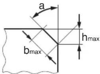
h_max =Max.chamfer height
b_max =Max.chamfer width
a = Chamfer angle
d_ =Minimum pipe diameter
m = Weight without mains cable
Measured values determined in conformity with EN 62841.
□ Machine in protection class II
\~ AC power
The technical specifications quoted are subject to tolerances (in compliance with relevant valid standards).

Emission values
These values make it possible to assess the emissions from the power tool and to compare different power tools. The actual load may be higher or lower depending on operating conditions, the condition of the power tool or the accessories used. Please allow for breaks and periods when the load is lower for assessment purposes. Arrange protective measures for the user, such as organisational measures based on the adjusted estimates.
Vibration total value (vector sum of three directions) determined in accordance with EN 62841:
a_h,SG = Vibration emission value
K_h,SG =Uncertainty (vibration)
Typical A-effective perceived sound levels:
L_pA =Sound pressure level
L_WA = Acoustic power level
K_pA, K_WA= Uncertainty
The noise level can exceed 80 dB(A) during operation.

Wear ear protectors!
Electromagnetic disturbances:
In individual cases, the speed may fluctuate temporarily if the machine is exposed to extreme external electromagnetic disturbances or the electronic restart protection may respond. In this case, switch the machine off and on again.
FRANÇAISfr
Notice originale
natural_image
Two 3D mechanical parts labeled A and B, showing different surfaces and features (no text or symbols beyond labels)natural_image
3D rendered mechanical component with a conical recess and flange (no text or symbols)K_h,SG =incertitude (vibration)
line
| x | y (mm) | | ---- | ------ | | 0 | 0 | | 2,0 | 3 |natural_image
Two 3D mechanical component views labeled A and B, showing different surface textures (no text or symbols beyond labels)natural_image
3D rendered mechanical component with a square base and central cavity (no text or symbols)line
| x | h (mm) | | ---- | ------ | | 0 | 0 | | 2,0 | 3 |natural_image
Two 3D mechanical parts labeled A and B, showing different surfaces and features (no text or symbols beyond labels)natural_image
3D rendered mechanical part with a V-shaped groove and central cavity (no text or symbols)line
| x | h (mm) | | ---- | ------ | | 0 | 0 | | 2,0 | 3 |natural_image
Two 3D mechanical component views labeled A and B, showing different angles and surfaces (no text or symbols beyond labels)natural_image
3D rendered mechanical component with a square base and central cavity (no text or symbols)line
| x | h (mm) | | ---- | ------ | | 0 | 0 | | 2,0 | 3 |natural_image
Two 3D mechanical parts labeled A and B, showing different surfaces and angles (no text or symbols beyond labels)natural_image
3D rendered mechanical component with a conical top and flange (no text or symbols)line
| x | h (mm) | | ---- | ------ | | 0 | 0 | | 2,0 | 3 |natural_image
Two 3D mechanical parts labeled A and B, showing different surfaces and features (no text or symbols beyond labels)natural_image
3D rendered mechanical component with a V-shaped groove and a square end (no text or symbols)natural_image
Two 3D mechanical parts labeled A and B, showing different surface profiles (no text or symbols beyond labels)natural_image
3D rendered mechanical component with a square base and central cavity (no text or symbols)L_pA =äänen painetaso
line
| x | h (mm) | | ---- | ------ | | 0 | 0 | | 2,0 | 3 |Velg fasehøyden du ønsker å stille inn i Y-aksen. Trekk en vannrett linje til snittpunktet med linjen. Fra dette snittpunktet trekker du en loddrett linje til X-aksen. Les verdien til X-aksen av. Denne verdien "X" må du nå stille inn på maskinen.
Merk: Diagrammet gjelder for materialer med rette kanter. Avrundede kanter på materialene må tas hensyn til när fresehøyden stilles inn.
Aluminium, kobber, messing 4-6
Stål til 400 N/mm ^2 ...... 4-6
Stål til 600 N/mm ^2 ...... 3-5
natural_image
Two 3D mechanical components labeled A and B, showing different surface surfaces (no text or symbols beyond labels)natural_image
3D rendered mechanical component with a square base and central cavity (no text or symbols)Aluminium, kobber, messing....4-6
Stål op til 400 N/mm ^2 ......4-6
Stål op til 600 N/mm ^2 ......3-5
Stål op til 900 N/mm ^2 ....2-4
Rustfrit stål....1-3
natural_image
Two 3D mechanical components labeled A and B, showing different surfaces and angles (no text or symbols beyond labels)natural_image
3D rendered mechanical part with a V-shaped groove and concentric grooves (no text or symbols)a_h,SG =vibrationsemission
K_n,SG=Usikkerhed (vibration)
natural_image
Two 3D mechanical parts labeled A and B, showing different surfaces and features (no text or symbols beyond labels)natural_image
3D rendered mechanical component with a conical recess and flange (no text or symbols)line
| x | h (mm) | | ---- | ------ | | 0 | 0 | | 2,0 | 3 |natural_image
Two 3D mechanical parts labeled A and B, showing different surfaces and features (no text or symbols beyond labels)natural_image
3D rendered mechanical component with a V-shaped groove and central cavity (no text or symbols)line
| x | h (mm) | | ---- | ------ | | 0 | 0 | | 2,0 | 3 |natural_image
Two 3D mechanical components labeled A and B, shown from different angles (no text or symbols beyond labels)natural_image
3D rendered mechanical part with a square flange and central hole (no text or symbols)line
| X | h (mm) | | ---- | ------ | | 0 | 0 | | 2,0 | 3 |natural_image
3D rendered object with a circular label 'A' in the corner (no text or symbols on the object itself)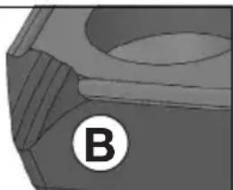
natural_image
Close-up of a mechanical component with a circular label marked 'B' (no readable text or symbols)natural_image
3D rendered mechanical part with a conical recess and flange (no text or symbols)natural_image
Two 3D mechanical components labeled A and B, shown from different angles (no text or symbols beyond labels)natural_image
3D rendered mechanical part with a V-shaped groove and central cavity (no text or symbols)line
| x / mm (One-Touch-Controller) | a = 15° | a = 30° | a = 45° | a = 60° | a = 75° | | ----------------------------- | ------- | ------- | ------- | ------- | ------- | | 0.001 | 0 | 0 | 0 | 0 | 0 | | 0.002 | 2 | 1 | 0.5 | 0.2 | 0.1 | | 0.003 | 4 | 2 | 1 | 0.4 | 0.2 | | 0.004 | 6 | 3 | 1.5 | 0.6 | 0.3 | | 0.005 | 8 | 4 | 2 | 0.8 | 0.4 | | 0.006 | 10 | 5 | 2.5 | 1 | 0.5 | | 0.007 | 12 | 6 | 3 | 1.2 | 0.6 | | 0.008 | 14 | 7 | 3.5 | 1.4 | 0.7 | | 0.009 | 16 | 8 | 4 | 1.6 | 0.8 | | 0.01 | 18 | 9 | 4.5 | 1.8 | 0.9 | | 0.01 | 20 | 10 | 5 | 2 | 1 | | 0.01 | 22 | 11 | 5.5 | 2.2 | 1.1 | | 0.01 | 24 | 12 | 6 | 2.4 | 1.2 | | 0.01 | 26 | 13 | 6.5 | 2.6 | 1.3 | | 0.01 | 28 | 14 | 7 | 2.8 | 1.4 | | 0.01 | 30 | 15 | 7.5 | 3 | 1.5 | The chart includes an inset image of a mechanical component with dimension 'h' and angle 'α'. The data is presented in a table format with rows and columns specified in the code.

natural_image
Icon showing an open book and a recycling bin with a circular arrow (no text or symbols)Metabowerke GmbH
Metabo-Allee 1
72622 Nuertingen
Germany
www.metabo.com
metabo®
PROFESSIONAL POWER TOOL SOLUTIONS


- Original instructions
- Declaration of Conformity
- Specified Conditions of Use
- General Safety Information
- Special Safety Instructions
- Kickback and related warnings
- ENGLISHen
- Additional Safety Instructions:
- Reducing dust exposure:
- Special safety instructions for mains powered machines:
- Overview
- Initial Operation
- Attaching the additional handle
- Attach bow handle (1)
- Fitting the side handle (5)
- Setting
- Setting the chamfer angle
- Setting the chamfer height
- Set the chamfer angle first:
- Setting the chamfer height:
- Use
- Switching on and off
- Continuous operation:
- Setting speed
- General working instructions
- Working on the outer edge of pipes
- Possibility to turn the base plate (13)
- Maintenance
- Changing indexable inserts
- Cleaning
- Troubleshooting
- Accessories
- Repairs
- Environmental Protection
- Technical Specifications
- Emission values
- Electromagnetic disturbances:
- FRANÇAISfr
- Notice originale
Brand : METABO
Model : KFMV 17-15 F
Category : Milling machine