DCLE34035 - Laser pointer DEWALT - Free user manual and instructions
Find the device manual for free DCLE34035 DEWALT in PDF.

| Product Type | 3×360° Self-Leveling Laser Level |
| Brand | DEWALT |
| Model | DCLE34035 |
| Power Supply | 18 V (XR lithium-ion battery) |
| Compatible Battery Type | DCB1810, DCB1820, DCB183/B/G, DCB184/B/G, DCB1870, DCB1890, DCBP034/G |
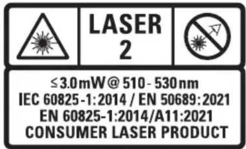
| Light Source | Laser diodes (Class 2) |
| Wavelength | 510–530 nm (visible) |
| Laser Power | ≤ 3 mW per line |
| Visible Range | Up to 80 m |
| Range with Detector (DE0892G-XJ) | Up to 100 m |
| Accuracy (Plumb and Level) | ±3.0 mm per 10 m |
| Self-Leveling Range | ±3° |
| Operating Temperature | -20°C to 60°C |
| Storage Temperature | -20°C to 60°C |
| Humidity | Max 80% at 31°C, linear to 50% at 40°C |
| Ingress Protection | IP54 (product only) |
| Main Features | Horizontal and vertical laser lines (front and side) 360°, manual tilt mode, remote control, magnetic bracket with height adjustment, drop indicator |
| Cleaning | Soft dry cloth, do not use solvents |
| Safety | Class 2 laser product, do not stare directly into the beam |
| Repairability | No user-serviceable parts, refer to authorized service center |
| Warranty | See DEWALT website (www.DEWALT.eu) |
| Typical Package Contents | Laser, remote control, magnetic bracket with vertical lift system, target card (depending on kit), manual |
Frequently Asked Questions - DCLE34035 DEWALT
User questions about DCLE34035 DEWALT
0 question about this device. Answer the ones you know or ask your own.
Ask a new question about this device
Download the instructions for your Laser pointer in PDF format for free! Find your manual DCLE34035 - DEWALT and take your electronic device back in hand. On this page are published all the documents necessary for the use of your device. DCLE34035 by DEWALT.
USER MANUAL DCLE34035 DEWALT
English (original instructions) 26
natural_image
Icon of a person using a computer (no text or symbols)Fig. A
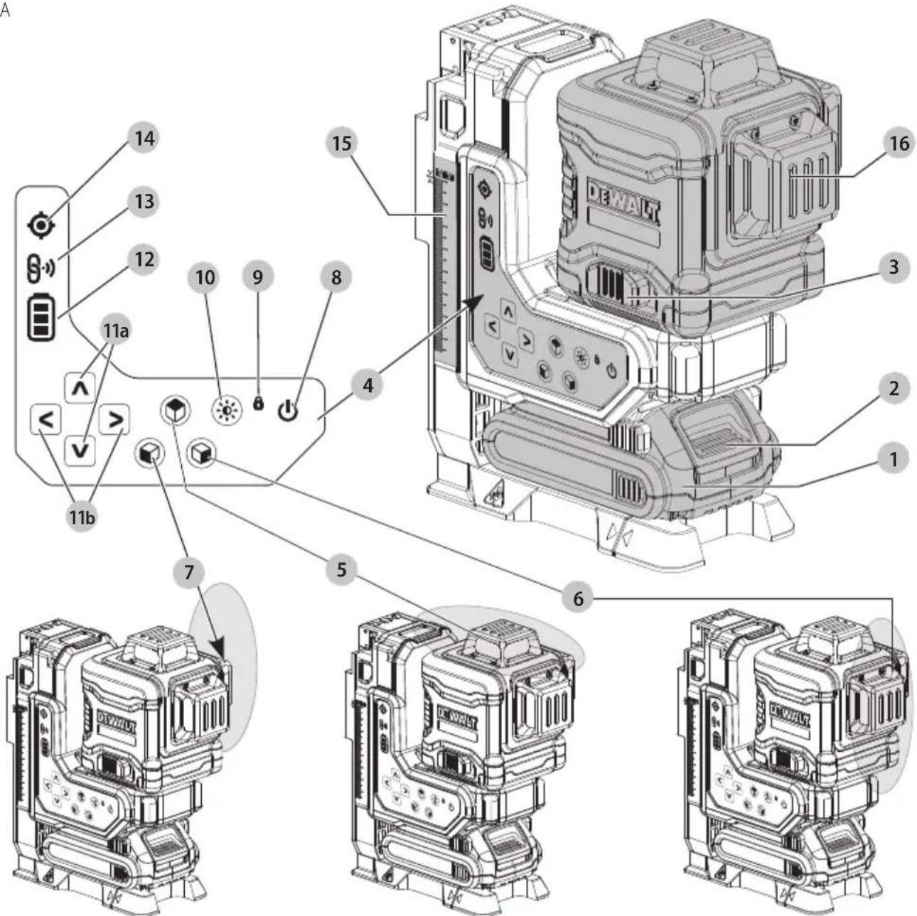
Fig. B
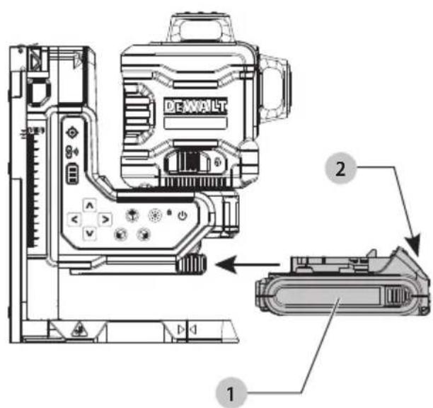
Fig. C
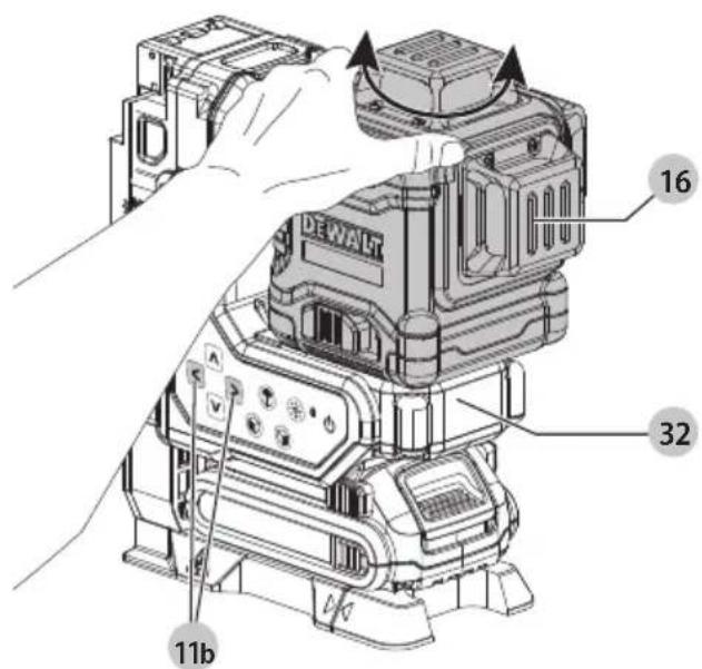
Fig. D
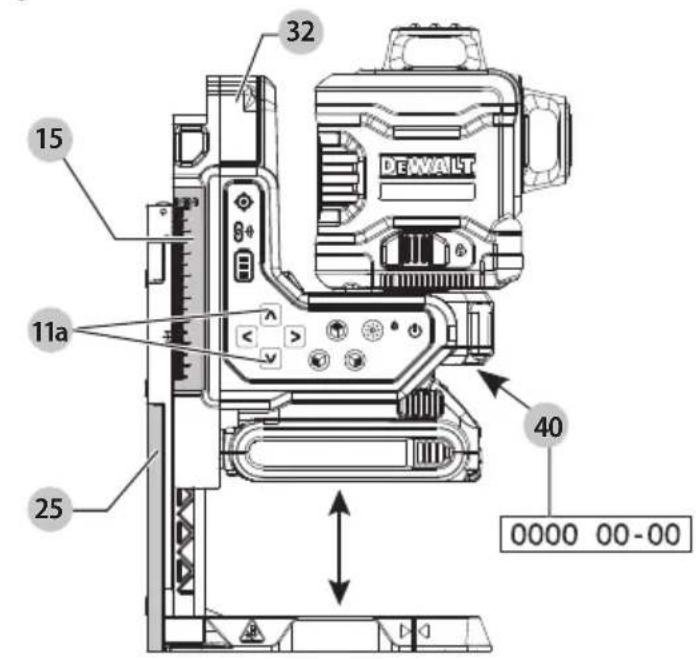
Fig. E
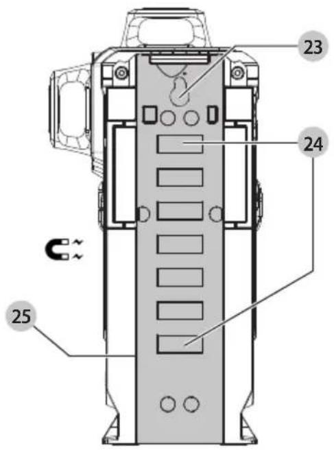
Fig. F
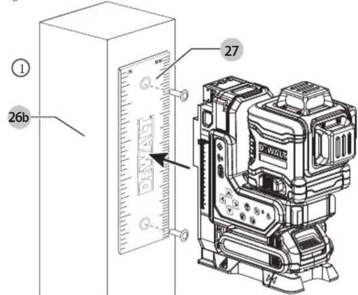
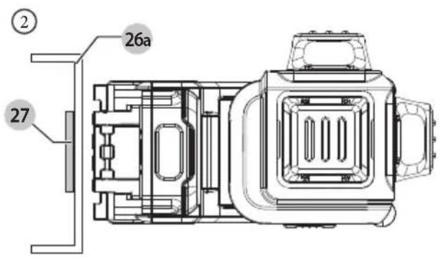
Fig. G
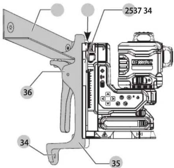
Fig. H
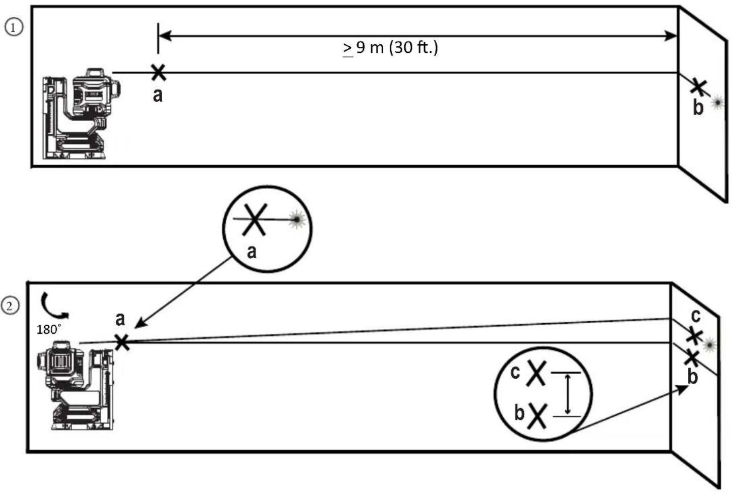
Fig.1
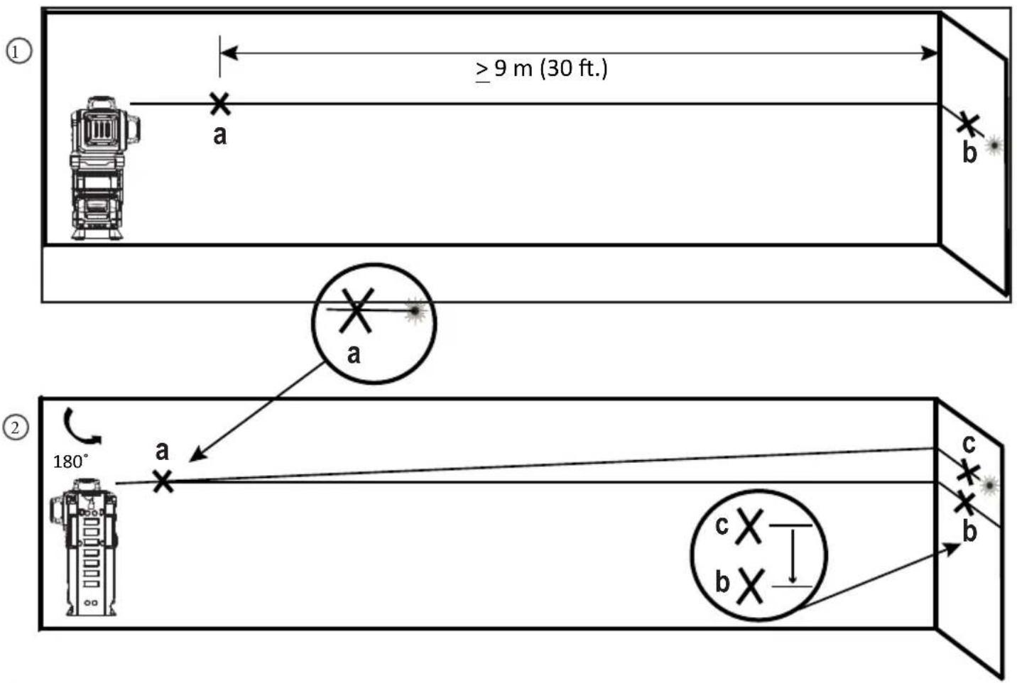
Fig. J
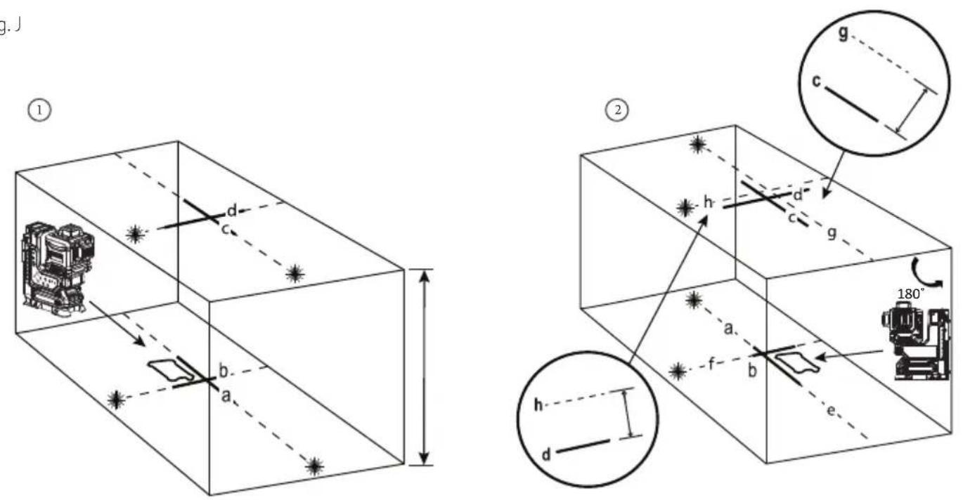
Fig. K
②
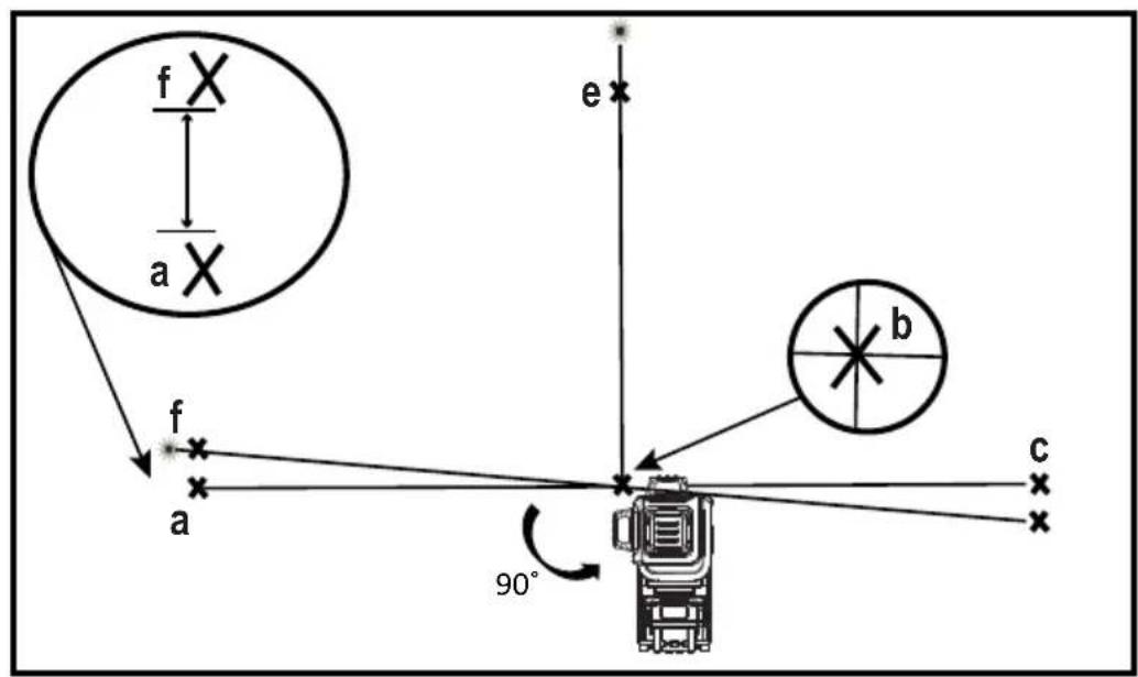
Fig. L
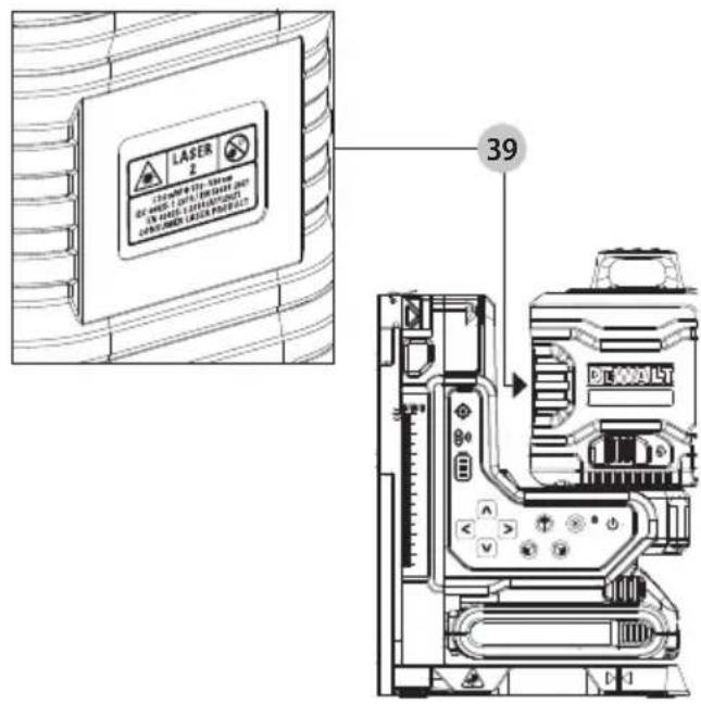
Fig. M
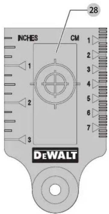
Fig. N
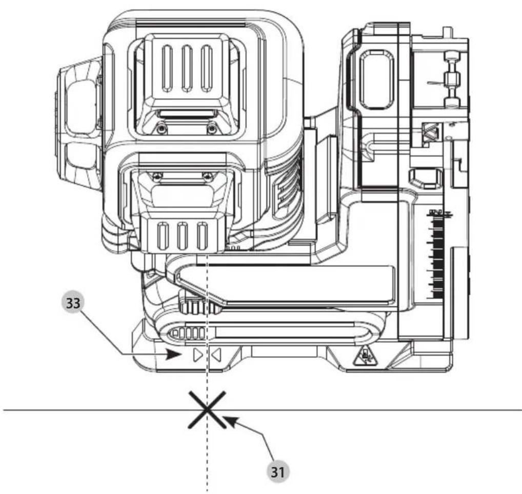
Fig. O
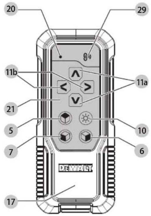
Fig. P
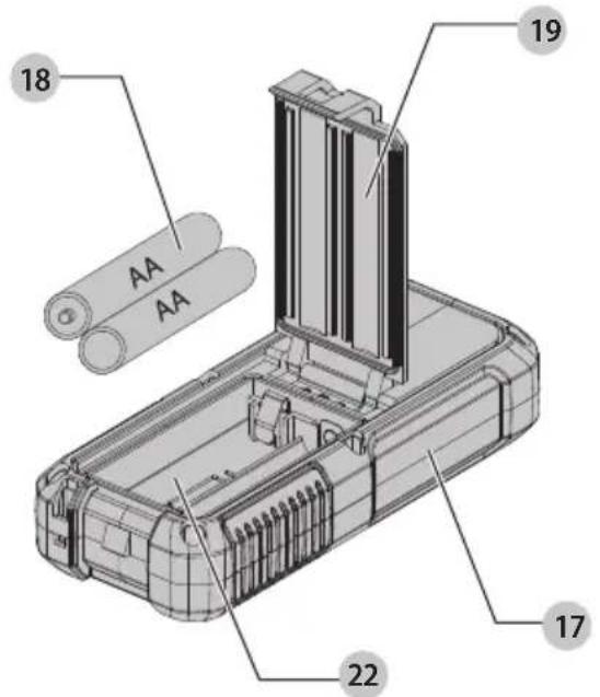
Fig. Q
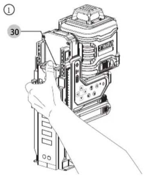
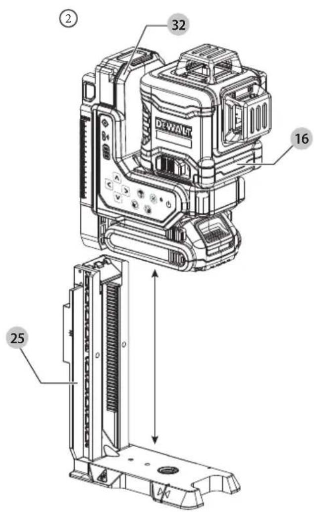
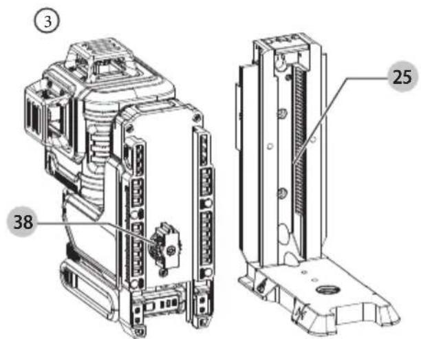
Fig. R Fig. S

natural_image
Line drawing of a surveying instrument mounted on a tripod, no text or symbols present18V XR 3X360 FJERNBETJENINGSLASER
DCLE34035

WARNING: Read all safety warnings, instructions, illustrations, and specifications in this manual, including the battery and charger sections provided in an original tool manual or the separate Batteries and Chargers manual. Manuals can be obtained by contacting

Customer Service (refer to the back page of this manual).
Technical Data
| DCLE34035 | |
| Voltage 18V | DC |
| Type 1 | |
| Light Source Laser diodes | |
| Laser Wavelength | 510 – 530 nm visible |
| Laser Power <=3 mW (each laser line) CLASS 2 LASER PRODUCT | |
| Range Up to 80 m (260 ft) Visible RangeUp to 100 m (330 ft) Maximum Range using DE0892G-XJ detector (sold separately)Up to 100 m (330 ft) Remote Cotrol Range using DE0892G-XJ detector (sold separately)For best range, keep the unit 1.5 m (5 ft) above the ground | |
| Accuracy (Plumb) ±3.0 mm per 10 m (±1/8" per 33') | |
| Accuracy (Level) ±3.0 mm per 10 m (±1/8" per 33') | |
| ContinuousFlashingLaser Lines | Tilt range exceeded/unit is not level |
| Power Source Refer to Battery Type section | |
| OperatingTemperature | -20 °C to 60 °C (-5 °F to 140 °F) |
| StorageTemperature | -20 °C to 60 °C (-5 °F to 140 °F) |
| Humidity Maximum | relative humidity 80% for temperatures up to 31°C (88°F), decreasing linearly to 50% relative humidity at 40°C (104°F) |
| Environmental Water & Dust Resistant to IP54. Applies to product, not battery or charger.WARNING: This product (not including the battery pack or charger) has an IP rating which provides some level of protection from dust (limited ingress) and liquids (light splashing) during normal and reasonably foreseeable use. The battery pack and charger do not have an IP rating on their own. NEVER submerge the product, battery or charger in liquid. | |

WARNING: To reduce the risk of injury, read the instruction manual.
Definitions: Safety Guidelines
The definitions below describe the level of severity for each signal word. Please read the manual and pay attention to these symbols.
RANGER: Indicates an imminently hazardous situation which, if not avoided, will result in death or serious injury.
WARNING: Indicates a potentially hazardous situation which, if not avoided, could result in death or serious injury.
▲AUTION: Indicates a potentially hazardous situation which, if not avoided, may result in minor or moderate injury.
NOTICE: Indicates a practice not related to personal injury which, if not avoided, may result in property damage.
▲penotes risk of electric shock.
Denotes risk of fire.
Safety Instructions for Lasers
WARNING! Read and understand all instructions. Failure to follow all instructions listed below may result in electric shock, fire and/or serious personal injury.
SAVE THESE INSTRUCTIONS
- Do not operate the laser in explosive atmospheres, such as in the presence of flammable liquids, gases or dust. Power tools create sparks which may ignite the dust or fumes.
- Use the laser only with the specifically designated batteries. Use of any other batteries may create a risk of fire.
- Store idle laser out of reach of children and other untrained persons. Lasers are dangerous in the hands of untrained users.
- Use only accessories that are recommended by the manufacturer for your model. Accessories that may be suitable for one laser, may create a risk of injury when used on another laser.
- Tool service MUST be performed only by qualified repair personnel. Repairs, service or maintenance performed by unqualified personnel may result in injury. For the location of your nearest authorized DEWALT repair agent, refer to the list of authorized DEWALT repair agents on back of this manual or visit www.2helpU.com on the Internet.
- Do not use optical tools such as a telescope or transit to view the laser beam. Serious eye injury could result.
- Do not place the laser in a position which may cause anyone to intentionally or unintentionally stare into the laser beam. Serious eye injury could result.
- Do not position the laser near a reflective surface which may reflect the laser beam toward anyone's eyes. Serious eye injury could result.
- Turn the laser off when it is not in use. Leaving the laser on increases the risk of staring into the laser beam.
- Do not operate the laser around children or allow children to operate the laser. Serious eye injury may result.
- Do not remove or deface warning labels. If labels are removed user or others may inadvertently expose themselves to radiation.
- Position the laser securely on a level surface. Damage to the laser or serious injury could result if the laser falls.
- Dress properly. Do not wear loose clothing or jewelry. Contain long hair. Keep your hair, clothing, and gloves away from moving parts. Loose clothing, jewelry or long hair can be caught in moving parts. Air vents often cover moving parts and should also be avoided.
WARNING: Use of controls or adjustments or performance of procedures other than those specified herein may result in hazardous radiation exposure.
WARNING! DO NOT DISASSEMBLE THE LASER. There are no user serviceable parts inside. Disassembling the laser will void all warranties on the product. Do not modify the product in any way. Modifying the tool may result in hazardous laser radiation exposure.
WARNING: Fire hazard! Avoid short-circuiting the contacts of a removed battery.
Additional Safety Instructions for Lasers
- Do not replace a laser diode with a different type. If damaged, have the laser repaired by an authorised repair agent.
- Do not use the laser for any purpose other than projecting laser lines.
- An exposure of the eye to the beam of a class 2 laser is considered safe for a maximum of 0.25 seconds. Eyelid reflexes will normally provide adequate protection.
- Never look into the laser beam directly and intentionally.
- Do not use optical tools to view the laser beam.
- Do not set up the tool at a position where the laser beam can cross any person at head height.
- Do not let children come in contact with the laser.
Residual Risks
The following risks are inherent to the use of this device:
• injuries caused by staring into laser beam.
Labels on the tool (Fig. L)
The following pictographs 39 are shown on the tool:

Read the instruction manual before use.

Laser warning.
Do not stare into the laser beam.
Personal Safety
- Stay alert, watch what you are doing, and use common sense when operating the laser level. Do not use the laser level when you are tired or under the influence of drugs, alcohol, or medication. A moment of inattention while operating the laser level may result in serious personal injury.
- Use personal protective equipment. Always wear eye protection. Depending on the work conditions, wearing protective equipment such as a dust mask, non-skid safety shoes, hard hat, and hearing protection will reduce personal injury.
Tool Use and Care
If the power button does not turn the laser line OFF, you may remove the battery to turn the laser off. Any tool that cannot be controlled with the power button is dangerous and must be repaired. See SERVICE AND REPAIRS.
Date Code Position (Fig. D)
The production date code 40 consists of a 4-digit year followed by a 2-digit week and is extended by a 2-digit factory code.
SAVE THESE INSTRUCTIONS
Battery Type
These battery packs may be used:
| Battery(kg)Battery(kg) | |
| DCB1810.35 DCB1870.54 | |
| DCB1820.61 DCB1890.54 | |
| DCB183/B/G0.40 DCBP034/G0.32 | |
| DCB184/B/G0.62 |
Refer to the battery/charger manual for more information.
Before First Time Use
- Check for damage to the tool, parts or accessories which may have occurred during transport.
• Take the time to thoroughly read and understand this manual prior to operation.
Description (Fig. A)
WARNING: Never modify the power tool or any part of it. Damage or personal injury could result.
1 Battery pack
2 Battery pack release button
3 Pendulum lock switch
4 Keypad
5 Horizontal laser line
6 Front vertical laser line
7 Side vertical laser line
8 Power button
9 Pendulum locked LED
10 Brightness level
11a Vertical motion buttons
11 horizontal pan buttons
12 Battery meter
13 Remote control link indicator LED
14 Drop indicator
15 Measurement scale
16 Laser head
Intended Use
The DCLE34035 3x360 Laser is a Class 2 laser product. It is a self-leveling laser tool that can be used for horizontal (level) and vertical (plumb) alignment projects.
DO nOT use under wet conditions or in presence of flammable liquids or gases.
This laser is a professional tool. DO nOT let children come into contact with the tool. Supervision is required when inexperienced operators use this tool.
• This product is not intended for use by persons (including children) suffering from diminished physical, sensory or mental
abilities; lack of experience, knowledge or skills unless they are supervised by a person responsible for their safety. Children should never be left alone with this product.
ASSEMBLY AND ADJUSTMENTS
WARNING: To reduce the risk of serious personal injury, turn tool off and disconnect battery pack before making any adjustments or removing/installing attachments or accessories. An accidental start-up can cause injury.
WARNING: Use only DEWALT batteries and chargers.
Installing and Removing the Battery Pack (Fig. B)
NOTE: For best results, make sure your battery pack is fully charged.
To install the battery pack 1 into the laser, align the battery pack with the rails under the front of the laser and slide in until the battery pack is firmly seated. Ensure that it does not disengage.
To remove the battery pack from the tool, press the battery pack release button 2 and firmly pull the battery pack out of the laser.
NOTE: Only use battery packs outlined in the Battery Type section. Using different battery packs other than recommended could result in damage to the unit.
OPERATION
Instructions for Use
WARNING: Always observe the safety instructions and applicable regulations.
WARNING: To reduce the risk of serious personal injury, turn tool off and disconnect battery pack before making any adjustments or removing/installing attachments or accessories. An accidental start-up can cause injury.
OPERATING TIPS (Fig. M)
- To extend battery life per charge, turn the laser off when it is not in use.
- To ensure the accuracy of your work, check the laser calibration often. Refer to Checking Laser Accuracy.
- Before attempting to use the laser, make sure it is positioned securely, on a smooth, flat stable surface that is level in both directions.
• To increase laser line visibility, use a Laser Target Card (Fig M).
AUTION: To reduce the risk of serious injury, never stare directly into the laser line with or without safety glasses. Refer to Accessories for important information.
• Always mark the center of the line created by the laser.
- Extreme temperature changes can cause movement or shifting of building structures, metal tripods, equipment, etc., which can affect accuracy. Check your accuracy often while working.
- If the laser has been dropped, check to make sure your laser is still calibrated. Refer to Checking Laser Accuracy.
TURNING THE LASER ON (Fig. A)
To turn on the laser:
- Insert fully charged battery pack 1.
-
Press the power button 8 on the keypad 4. The laser has a memory function, so the line settings from previous use will be retained when powering on the unit.
-
Each laser line is powered on by pressing its button on the keypad 4. Pressing the button again turns the laser line off. All laser lines may be operated at the same time or individually.
| Button D | Displays |
| Horizontal laser line 5 | |
| Front vertical laser line 6 | |
| Side vertical laser line 7 |
NOTE: When the laser is not in use, press the power button 8 to turn the laser OFF and slide the pendulum lock switch 3 to the left into locked position.
Laser Line Brightness (Fig. A)
The brightness of the laser lines can be adjusted by pressing the brightness level 10 button on the keypad 4 which will cycle through high, medium, and low brightness.
Viewing the Battery Meter (Fig. A)
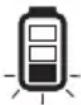
When the laser is ON, the battery meter 12 on the keypad indicates how much power remains.
- The bottom LED will illuminate and flash when the battery level is low (<20%). Laser unit will shut down.
• After the battery is charged, and the laser is turned ON again, the laser line(s) will return to full brightness and the battery indicator level will indicate full capacity. - If all LEDs on the battery meter remain ON, this indicates that the laser is not fully powered OFF.
| BATTERY METER LED | STATE OF CHARGE |
 | Battery Pack is 81–100% charged |
 | Battery Pack is 61–80% charged |
 | Battery Pack is < 60% charged |
 | Battery pack is < 20% charged/Laser is turned off |
Using the DCLEARCRC1 Remote Control (Fig. A, O)
The remote control 17 allows one person to set up and operate the laser from a distance. This unit comes with the remote control and the laser paired.
To operate, turn laser ON and press any button on remote control to wake it up. Remote will connect to the laser within 30 seconds. This will be indicated by remote control link indicator LED 13 lighting up solid and remote LED light 20 blinking blue. Remote control will go to sleep after 60 seconds of inactivity. To wake it up and reconnect press any button on remote control.
To pair a new remote control or re-pair an old remote control with the laser:
- Remote can be paired within 60 seconds of powering ON the laser. Remote control link indicator LED 13 on the laser keypad 4 will blink when in pairing mode.
- Place the remote control 17 close to the laser and press the remote link button 29 for a long duration on the remote control. The LED light 20 on the remote control will blink blue and remote control link indicator LED 13 on the laser keypad will light up solid when engaged.
The functions on the remote keypad 21 are identical to the functions on the laser unit itself (vertical motion buttons 11a, horizontal pan buttons 11b, horizontal laser line 5, front vertical laser line 6, side vertical laser line 7, brightness level 10).
LED LIGHT DIAGNOSIS SOLUTION
| OFF Remote control is not turned on. (Not Engaged) /Remote control batteries have no charge. | Press any button on the remote/Replace AA batteries. | |
| BLINKS RED THREE TIMES | Remote Control has a bad connection with the laser unit. | Move closer to the Laser Unit and press remote link button. |
| BLINKS BLUE Remote Control has a good connection with the laser unit. | ||
| BLINKS RED NINE TIMES | Remote Control has a low charge. | Replace AA batteries. |
NOTE: The remote control will go into sleep mode after 60 seconds. Selecting any button will reengage the remote with the laser.
Installing Batteries into the Remote Control (Fig. P)
The remote control 17 is powered by two AA batteries 18. To install the batteries provided:
- Lift up on the battery compartment cover 19.
- Insert two fresh AA batteries into the battery compartment 22, placing the batteries according to the (+) and (-) marked inside.
NOTE: For long battery life, always replace with a new set of AA batteries.
WARNING: Batteries can explode, or leak, and can cause injury or fire. To reduce this risk:
- Carefully follow all instructions and warnings on the battery label and package.
• Always insert batteries correctly with regard to polarity (+ and -), marked on the battery and the equipment.
- Do not short battery terminals.
- Do not charge batteries.
- Do not mix old and new batteries. Replace all of them at the same time with new batteries of the same brand and type.
- Remove dead batteries immediately and dispose of per local codes.
- Do not dispose of batteries in fire.
- Keep batteries out of reach of children.
- Remove batteries if the device will not be used for several months.
CHECKING LASER ACCURACY (Fig. A)
The laser tools are calibrated and sealed at the factory. It is recommended that you perform an accuracy check prior to using the laser for the first time (in case the laser was exposed to extreme temperatures) and then regularly to ensure the accuracy of your work. Refer to FIELD CALIBRATION CHECK.
When performing any of the accuracy checks listed in this manual, follow these guidelines:
- Use the largest area/distance possible, closest to the operating distance. The greater the area/distance, the easier to measure the accuracy of the laser.
- Place the laser on a smooth, flat, stable surface that is level in both directions.
• Mark the center of the laser line. - Set laser to low brightness level 10. Refer to Laser Line Brightness.
FIELD CALIBRATION CHECK
Horizontal Laser Line - Pitch Direction (Fig. A, H1, H2)
Checking the horizontal pitch calibration of the laser requires a wall at least 9 m (30") long, intersecting perpendicularly with another wall. It is important to conduct a calibration check using a distance no shorter than the distance of the applications for which the tool will be used.
- Place the laser no more than 0.30 m (1') away to the front wall, at least 9.0 m (30') away from the side wall, on a smooth, flat, stable surface or a tripod that is level in both directions (Fig. H1).
- Power on the laser and slide the pendulum lock switch 3 to the right allowing the laser to self level. Refer to USING THE LASER.
- Press the horizontal laser line 5 button to turn on the horizontal laser line.
- Mark (a) on front wall and (b) on side wall, along the laser line at least 9 m (30') apart (Fig. H1).
- Rotate the laser 180° (Fig. H2).
- Verify that the center of the laser line is aligned with (a) (Fig. H2).
- Directly above or below (b), mark (c) along the laser line (Fig. H2).
- Measure the vertical distance between (b) and (c).
- If your measurement is greater than the Allowable Distance Between (b) and (c) for the corresponding Distance Between mark (a) and (b) in the following table, the laser must be serviced at an authorized service center.
| Distance Between a and b | Allowable Distance Between b and c |
| 9.0 m (30') 6.2 mm (1/4") | |
| 12.0 m (40') 8.3 mm (5/16") | |
| 15.0 m (50') 10.4 mm (13/32") | |
Horizontal Laser Line - Roll Direction (Fig. A, I1, I2)
Checking the horizontal roll calibration of the laser requires a wall at least 9 m (30') long intersecting perpendicularly with another wall. It is important to conduct a calibration check using a distance no shorter than the distance of the applications for which the tool will be used.
-
Place the laser no more than 0.30 m (1') away to the front wall at least 9 m (30') away from the side wall, on a smooth, flat, stable surface or a tripod that is level in both directions (Fig. I1).
-
Power on the laser and slide the pendulum lock switch 3 to the right allowing the laser to self level. Refer to USING THE LASER.
- Press the horizontal laser line 5 button to turn on the horizontal laser line.
- Mark (a) on front wall and (b) on side wall, along the laser line at least 9 m (30') apart (Fig. 11).
- Rotate the laser 180^ (Fig. I2).
- Verify the center of the laser line is aligned with (a) (Fig. 12).
- Directly above or below (b), mark (c) along the laser line (Fig. I2).
- Measure the vertical distance between (b) and (c).
- If your measurement is greater than the Allowable Distance Between (b) and (c) for the corresponding Distance between mark (a) and (b) in the following table, the laser must be serviced at an authorized service center.
| Distance Between a and b | Allowable Distance Between a and c |
| 9.0 m (30') 6.2 mm (1/4") | |
| 12.0 m (40') 8.3 mm (5/16") | |
| 15.0 m (50') 10.4 mm (13/32") |
Vertical Laser Line (Fig. A, J1, J2)
Checking the vertical (plumb) calibration of the laser can be most accurately done when there is a substantial amount of vertical height available, ideally 6 m (20'), with one person on the floor positioning the laser and another person near a ceiling to mark the position of the laser line. It is important to conduct a calibration check using a distance no shorter than the distance of the applications for which the tool will be used.
- Place the laser on a smooth, flat, stable surface that is level in both directions (Fig. J1).
- Power on the laser and slide the pendulum lock switch 3 to the right allowing the laser to self level. Refer to USING THE LASER.
- Press the front and side vertical line buttons 6, 7 to turn on both vertical laser lines.
- Mark two short lines where the laser lines cross (a), (b) and also on the ceiling (c), (d). Always mark the center of the laser line (Fig. J2).
- Pick up and rotate the laser 180°, and position it so the laser lines line up with the marked lines on the level surface (e), (f) (Fig. J2).
- Mark two short lines where the laser lines cross on the ceiling (g), (h).
- Measure the distance between each set of marked lines on the ceiling (c, g and d, h). If the measurement is greater than the values shown below, the laser must be serviced at an authorized service center.
| Ceiling Height Allowable Distance Between Marks |
| 2.5 m (8') 1.7 mm (1/16") |
| 3.0 m (10') 2.1 mm (3/32") |
| 4.0 m (14') 2.8 mm (1/8") |
| 6.0 m (18') 4.1 mm (5/32") |
| 9.0 m (20') 6.2 mm (11/64") |
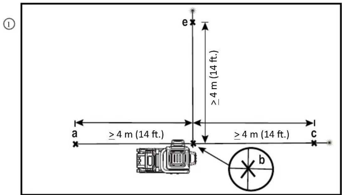
90° Accuracy Between Vertical Laser Lines (Fig. A, K1, K2)
Checking 90° accuracy requires an open floor area at least 10 m x 5 m (33' x 18'). Refer to Fig. K for the position of the laser at each step and for the location of the marks made at each step. Always mark the center of the laser line's thickness.
- Place the laser on a smooth, flat, stable surface that is level in both directions (Fig. K1).
- Power on the laser and slide the pendulum lock switch 3 to the right allowing the laser to self level. Refer to USING THE LASER.
- Press the front vertical laser line 6 and side vertical laser line 7 buttons to turn on both laser lines.
- Mark the center of the laser line at four locations (a, b, c, e) on the surface (Fig. K1).
- Rotate the laser 90° so the side vertical laser line now passes through (b) and (e). Front vertical laser line should pass through (b) (Fig. K2).
- Directly above or below (a), mark (f) along the front vertical laser line.
- Measure the distance between (a) and (f). If the measurement is greater than the values shown below, the laser must be serviced at an authorized service center.
| Distance from a to b | Allowable Distance Between a and f |
| 4 m (14') 3.5 mm (5/32") | |
| 5 m (17') 4.4 mm (3/16") | |
| 6 m (20') 5.3 mm (7/32") | |
| 7 m (23') 6.2 mm (1/4") |
USING THE LASER (Fig. A)
The laser lines produced by the laser head 16 can be used in two modes: Self Leveling and Manual Slope.
Self-Leveling Mode (Fig. A)
To use laser lines in self-leveling mode, slide pendulum lock switch 3 to the right. This will reveal an unlocked symbol Each laser is calibrated at the factory to find level as long as it is positioned on a flat surface within average ± 3^ of level. No manual adjustments are required.
If the laser has been tilted so much that it cannot self-level (>3°), the laser line will flash every one second.
When the laser lines flash as noted above THE LASER IS NOT LEVEL (OR PLUMB) AND SHOULD NOT BE USED FOR DETERMINING OR MARKING LEVEL OR PLUMB.
Try repositioning the laser on a more level surface.
Manual Slope Mode (Fig. A)
To use laser lines in manual slope mode, slide pendulum lock switch 3 to the left. This will reveal a locked symbol. The pendulum locked LED 9 will illuminate when the laser is locked. Self-leveling mechanism will be disabled, and laser can be inclined or rotated to project laser lines at any oblique angle. In manual slope mode laser lines will flash every 10 seconds.
NOTE: Always store the laser with pendulum lock switch 3 in locked mode 🔒.
Line Position/Primary Layout Point (Fig. N)
Place laser to align the line position notch 33 close to the primary layout point 31 along laser line. This will ensure minimal shift of the laser line from layout point during rotational adjustment of laser head. Always verify that laser line is passing through layout point after rotational adjustment.
Rotating the Laser Head (Fig. A, C, O)
The laser head 16 is permanently attached to the laser base 32 containing the battery pack 1. This laser head can be manually rotated by hand by gripping the laser head and rotating.
Pressing the left or right horizontal pan buttons 11b on the laser keypad 4 or the laser remote control 17 will rotate the laser head.
-
Short press duration of the horizontal pan buttons 11b will provide step movement of the laser head/line.
-
Long press duration of the horizontal pan buttons will provide continuous higher speed movement of the laser head line.
Height Adjustment (Fig. A, D, O, Q2)
WARNING: Keep fingers clear of pinch point between the battery pack 1 and the base of the magnetic vertical lift bracket 25. Serious personal injury or damage to the laser may result.
The magnetic vertical lift bracket 25 contains a gear mechanism 38 allowing the height of the laser head 16 to be adjusted. Pressing the vertical motion buttons 11a on the laser keypad 4 or on the laser remote control 17 will raise and lower the position of the laser head. The laser base 32 can also be pulled up or pushed down manually by hand.
To adjust the height:
- Short press duration of the vertical motion buttons 11a will provide step movement of the laser head/line.
- Long press duration of the vertical motion buttons will provide continuous higher speed movement of the laser head line.
Both sides of the magnetic vertical lift bracket contain a different measurement scale 15 (mm, inches) that can be used as a visual reference when moving the laser up/down.
NOTE: The magnetic vertical lift bracket is equipped with a timeout feature which will shut off any engaged height adjustments after 30 seconds of continuous movement.
Using the Magnetic Vertical Lift Bracket (Fig. E)
The laser has a magnetic vertical lift bracket 25 permanently attached to the unit.
WARNING: Position the laser and/or wall mount on a stable surface. Serious personal injury or damage to the laser may result if the laser falls.
- The magnetic vertical lift bracket has a keyhole slot 23 so it can be hung from a nail or screw on any kind of surface for storage purpose.
- The magnetic vertical lift bracket has magnets 24 which allow the unit to be mounted to most upright surfaces made of steel or iron. Common examples of suitable surfaces include steel framing studs, steel door frames, and structural steel beams and wooden stud.
Refer to Multi-Surface Mounting Plate and Ceiling Mount.
Drop Indicator (Fig. A)
If the laser experiences more than a 1m (3.25') drop, the drop indicator 14 LED will illuminate indicating a laser calibration check will need to be performed. Refer to FIELD CALIBRATION CHECK. Remove and reinstall battery to turn OFF the drop indicator LED.
LED LIGHT DIAGNOSIS SOLUTION
| OFF No freefall has been detected. | |
| SOLID BRIGHT Laser detected a freefall for at least 1m. | Conduct a laser accuracy calibration check. Refer to FIELD CALIBRATION CHECK. |
NOTE: Drop detect only works with battery pack 1 installed and laser turned ON.
MAINTENANCE
Your laser level has been designed to operate over a long period of time with a minimum of maintenance. Continuous satisfactory operation depends upon proper tool care and regular cleaning.
WARNING: To reduce the risk of serious personal injury, turn laser level off before making any adjustments or removing/installing attachments or accessories. An accidental start-up can cause injury.
The charger and battery pack are not serviceable.
- To maintain the accuracy of your work, check the laser often to make sure it is properly calibrated. Refer to Field Calibration Check.
- Calibration checks and other maintenance repairs may be performed by DEWALT service centers.
- When not in use, store the laser in the kit box provided. Do not store your laser at temperatures below -20^ (-5°F) or above 60^ (140°F).
- Do not store your laser in the kit box if the laser is wet. The laser should be dried first with a soft, dry cloth prior to storage.
- Cleaning exterior plastic parts may be cleaned with a damp cloth. Although these parts are solvent resistant, NEVER use solvents. Use a soft, dry cloth to remove moisture from the tool before storage.
Cleaning the Vertical Lift Mechanism (Fig. A, Q1–Q3)
WARNING: Never use a pressure washer or compressed air for clearing jams or debris from the laser. Gently brush away any debris with a soft brush.
WARNING: Keep fingers clear of pinch point between the battery pack 1 and the base of the magnetic vertical lift bracket 25. Serious personal injury or damage to the laser may result.
WARNING: Keep fingers clear of pinch point between the service door 30 and magnetic vertical lift bracket 25. Serious personal injury or damage to the laser may result. The service door 30 opening, located on the top of the laser unit, allows for the magnetic vertical lift bracket 25 to be separated from the laser base 32 and for clearing any jams in mechanism.
Seperating Laser Head from Magnetic Vertical Lift Bracket
WARNING: Do not place fingers in between the lift bracket 25 and laser base 32. Serious personal injury or damage to the laser may result.
To disconnect the magnetic vertical lift bracket 25 from the laser head 16 :
- Place the laser on a flat level surface.
- Flip service door 30 down (Fig. Q1) by placing thumb in the notch behind the service the door and pushing it down.
- Lift the laser base 32 straight up and separate the laser head 16 from the magnetic vertical lift bracket 25 (Fig. Q2).
- Use a soft brush to remove dust from the gear mechanism 38 and inside of the magnetic vertical lift bracket 25 (Fig. Q3).
Cleaning
WARNING: Never use solvents or other harsh chemicals for cleaning the non-metallic parts of the laser level. These chemicals may weaken the materials used in these parts. Use a cloth dampened only with water and mild soap. Never let any liquid get inside the laser level; never immerse any part of the laser level into a liquid.
Exterior plastic parts may be cleaned with a damp cloth. Although these parts are solvent resistant, NEVER use solvents. Use a soft, dry cloth to remove moisture from the laser level before storage.
TROUBLESHOOTING (Fig. A)
This laser is a complex electronic and optical instrument. In case the laser does not function as expected, remove battery pack 1 and reinstall after 5 seconds. If problem persists, call service center. Refer to SERVICE AND REPAIRS.
The Laser Does Not Turn On
- Fully charge the battery pack and then reinstall it in the laser unit.
- If the laser unit is exposed to extremely hot temperatures, the unit will not turn on. If the laser has been stored in extremely hot temperatures, allow it to cool. The laser level will not be damaged by pressing the on/off button before cooling to its proper operating temperature.
Laser Line Flashing Patterns
Laser has two flashing patterns.
- Flashing every 1 second - Laser is out of level (>3^) in self-leveling mode.
- Flashing every 10 seconds - Laser is in manual slope mode. Refer to USING THE LASER.
ACCESSORIES (Fig. R)
The laser is equipped with a 5/8 - 11 female thread on the bottom of the unit (Fig. R).
This thread is to accommodate current or future DEWALT accessories. Only use DEWALT accessories specified for use with this product. Follow the directions included with the accessory.
WARNING: Since accessories, other than those offered by DEWALT, have not been tested with this product, use of such accessories with this tool could be hazardous. To reduce the risk of injury, only DEWALT recommended accessories should be used with this product.
If you need any assistance in locating any accessory, please contact your nearest DEWALT service center or go to
www.DEWALT.com.
Ceiling Mount (Fig. F1, G)
The laser is packaged with a drop ceiling mount 35. The drop ceiling mount offers more mounting options for the laser. The drop ceiling mount has a clamp 36 at one end which can be fixed to a wall angle for acoustic ceiling installation 37. At each end of the ceiling mount is a screw hole 34, allowing the ceiling mount to be attached to a wooden stud 26b with a nail or screw.
Once the ceiling mount is secured, its steel plate provides a surface to which the magnetic vertical lift bracket 25 can be attached.
Multi-Surface Mounting Plate (Fig. E, F1, F2)
- To attach the laser to a wooden stud 26b, screw in multi-surface mounting plate 27 first and mount laser using laser magnets 24 (Fig. E, F1).
- To attach the laser to a metal stud 26a, sandwich the metal stud between the multi-surface mounting plate 27 and the laser magnets 24 (Fig. E, F2). Placing the multi-surface mounting plate behind the metal stud will significantly increase the magnetic strength and holding capacity of the laser.
Target Card (Fig. M)
Some laser kits include a Laser Target Card 28 (Fig. M) to aid in locating and marking the laser line. The target card enhances the visibility of the laser line as the laser line crosses over the card. The card is marked with standard and metric scales. The laser line passes through the semi-transparent plastic and reflects off of the reflective tape on the reverse side. The magnet at the top of the card is designed to hold the target card to ceiling track or steel studs to determine plumb and level positions. For best performance when using the Target Card, the DEWALT logo should be facing you.
Optional Accessories (Fig. S)
The following accessories are compatible with your laser.
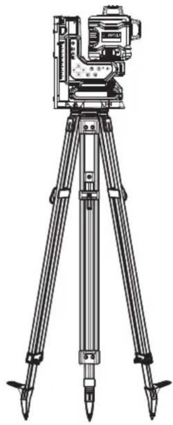
Tripod Mount: DE0736-XJ (Fig. S)
The DW0737 Construction Tripod has a lightweight, durable aluminum construction and is easy to transport. Features flat head design, and pointed steel feet are stable on any terrain.
Digital Laser Detector: DE0892G-XJ
For additional range, this laser unit is compatible with a Digital Laser Detector.
The DEWALT Digital Laser Detector helps in locating a laser line emitted by the laser in bright light conditions or over long distances. The detector can be used in both indoor and outdoor situations where it is difficult to see the laser line.
SERVICE AND REPAIRS
NOTE: Disassembling the laser level(s) will void all warranties on the product.
To assure product SAFETY and RELIABILITY, repairs, maintenance and adjustment should be performed by authorized service centers. Service or maintenance performed by unqualified personnel may result in a risk of injury. To locate your nearest DEWALT service center go to www.DEWALT.eu.
WARRANTY
Go to www.DEWALT.eu for the latest warranty information.
Protecting the Environment

Separate collection. Products and batteries marked with this symbol must not be disposed of with normal household waste.

Products and batteries contain materials that can
be recovered or recycled, reducing the demand for raw materials. Please recycle electrical products and batteries
according to local provisions. Further information is available at www.2helpU.com.
Rechargeable Battery Pack
This long-life battery pack must be recharged when it fails to produce sufficient power on jobs that were easily done before. At the end of its technical life, discard it with due care for our environment:
- Run the battery pack down completely, then remove it from the tool.
- Li-Ion cells are recyclable. Take them to your dealer or a local recycling station. The collected battery packs will be recycled or disposed of properly.
LÁSER CON MANDO A DISTANCIA DE 18V XR 3X360 DCLE34035

VOYanT DiaGnOsTiC sOLUTiOn
Bloc-batterie rechargeable
LED-MERKKIVALO VIANMÄÄRITYS RATKAISU