DW071 - Laser pointer DEWALT - Free user manual and instructions
Find the device manual for free DW071 DEWALT in PDF.

| Product type | Rotary laser |
| Brand | DeWalt |
| Model | DW071 |
| Voltage | 4.5 V |
| Battery type | 3 x LR14 (alkaline) |
| Rotation speed | 0 - 600 rpm (variable) |
| Laser class | II (EN 60825-1) |
| Protection rating | IP54 |
| Operating temperature | 0 °C to 40 °C |
| Receptacle thread | 5/8" x 11 |
| Weight | 3.0 kg |
| Main functions | Projection of horizontal (level) and vertical (plumb) lines, stationary laser point |
| Package contents | Laser, wall mount, target card, glasses, 3 LR14 batteries, carrying case, instruction manual |
| Maintenance and cleaning | Clean the housing with a soft cloth; lens with a soft cloth or alcohol-moistened cotton swab |
| Safety | Do not look directly into the beam; use the supplied glasses to improve visibility; keep out of reach of children |
| Optional accessories | Laser detector DE0732, graduated rod DE0734, tripod DE0736 |
| Warranty | 1 year against manufacturing defects, 30 days satisfaction or refund, 1 year free maintenance |
Frequently Asked Questions - DW071 DEWALT
User questions about DW071 DEWALT
0 question about this device. Answer the ones you know or ask your own.
Ask a new question about this device
Download the instructions for your Laser pointer in PDF format for free! Find your manual DW071 - DEWALT and take your electronic device back in hand. On this page are published all the documents necessary for the use of your device. DW071 by DEWALT.
USER MANUAL DW071 DEWALT
C2
C3
C4
C5
D1
D2
natural_image
3D rendering of a mechanical device mounted on a base, shown in isometric view with no visible text or symbols.E1
natural_image
Technical line drawing of a mechanical device with labeled component '13' (no text or symbols beyond label)E2
natural_image
Line drawing of a surveying instrument mounted on a tripod against a plain background (no text or symbols)E3
E4
F
G
313 2 321
H
natural_image
Illustration of a pair of sunglasses with black frame and gray lenses (no text or symbols)11
12
natural_image
Technical line drawing of a mechanical device with two views: top view shows internal components, bottom view shows external assembly (no text or symbols)13
ROTATIONSLASER DW071
Tillykke!
TUV Rheinland of North America
File Number E2071161.02-A1
You have chosen a DEWALT power tool.
Years of experience, thorough product development and innovation make DEWALT one of the most reliable partners for professional power tool users.
Technical data
| DW071 | |
| Voltage V 4.5 | |
| Battery size 3 x LR14 (D) | |
| Rotary speed min | -1 0 - 600 |
| Laser class II | |
| Protection class IP54 | |
| Operating temperature °C 0 - 40 | |
| Receptacle thread 5/8" x 11 | |
| Weight kg 3.0 | |
The following symbols are used throughout this manual:

Denotes risk of personal injury, loss of life or damage to the tool in case of non-observance of the instructions in this manual.

Fire hazard.
EC-Declaration of conformity

DW071
DEWALT declares that these tools have been designed in compliance with: 73/23/EEC, 98/37/EEC, 89/336/EEC, EN 60335, EN 55014-1, EN 55014-2, EN 61000-3-2, EN 61000-3-3, EN 60825-1 & EN 61010-1.
For more information, please contact DEWALT at the address below or refer to the back of the manual.
| DW071 | ||
| L_pA (sound pressure) dB(A)* < 70 | ||
| Weighted RMS acceleration value m/s | 2 | < 2.5 |
* at the operator's ear
TUV Rheinland of North America
File Number E2071161.02-A1
Director Engineering and Product Development Horst Großmann

D-65510, Idstein, Germany
Safety instructions
When using power tools, always observe the safety regulations applicable in your country to reduce the risk of fire, electric shock and personal injury.
Read all of this manual carefully before operating the tool. Also refer to the manual of any power tool that will be used with this tool.
Save this manual for future reference.
General
1 Keep work area clean
Cluttered areas and benches can cause accidents.
2 Consider work area environment
Do not expose power tools to humidity.
Keep work area well lit. Do not use power tools in the presence of flammable liquids or gases.
3 Guard against electric shock
Prevent body contact with earthed surfaces (e.g. pipes, radiators, cookers and refrigerators). For use under extreme conditions (e.g. high humidity, when metal swarf is being produced, etc.) electric safety can be improved by inserting an isolating transformer or a (FI) earth-leakage circuit-breaker.
4 Keep children away
Do not let children come into contact with the tool or extension cord. Supervision is required for those under 16 years of age.
5 Use appropriate tool
The intended use is described in this instruction manual. Do not force small tools or attachments to do the job of a heavy-duty tool.
The tool will do the job better and safer at the rate for which it was intended.
Warning! The use of any accessory or attachment or performance of any operation with this tool, other than those recommended in this instruction manual may present a risk of personal injury.
6 Maintain tools with care
Keep the tools in good condition and clean for better and safer performance.
Follow the instructions for maintenance and changing accessories. Inspect the tool cords at regular intervals and, if damaged, have them repaired by an authorized DEWALT repair agent. Keep all controls dry, clean and free from oil and grease.
7 Store idle tools
When not in use, power tools must be stored in a dry place and locked up securely, out of reach of children.
8 Check for damaged parts
Before using the tool, carefully check it for damage to ensure that it will operate properly and perform its intended function. Check for misalignment and seizure of moving parts, breakage of parts and any other conditions that may affect its operation. Have damaged guards or other defective parts repaired or replaced as instructed.
Do not use the tool if the switch is defective.
Have the switch replaced by an authorized DEWALT repair agent.
9 Remove the batteries
Remove the batteries when not in use, before servicing and when changing accessories.
10 Have your tool repaired by an authorized DEWALT repair agent
This power tool is in accordance with the relevant safety regulations. To avoid danger, electric appliances must only be repaired by qualified technicians.
Additional safety instructions for rotary lasers
- This laser complies with class 2 according to EN 60825-1:1994+A11. Do not replace a laser diode with a different type. If damaged, have the laser repaired by an authorised repair agent.
- Do not use the laser for any purpose other than projecting laser lines.
An exposure of the eye to the beam of a class 2 laser is considered safe for a maximum of 0.25 seconds. Eyelid reflexes will normally provide adequate protection. At distances over 1 m, the laser complies with class 1 and thus is considered completely safe.
- Never look into the laser beam directly and intentionally.
- Do not use optical tools to view the laser beam.
- Do not set up the tool at a position where the laser beam can cross any person at head height.
- Do not let children come in contact with the laser.
Additional safety instructions for batteries
- Do not open or mutilate batteries for any reason.
- Do not expose batteries to water.
- Do not expose batteries to fire.
- Do not store batteries in locations where the temperature may exceed 40 °C.
- Use only the correct size of batteries. When replacing, do not mix old batteries with new ones.
- Under extreme conditions, battery leakage may occur. When you notice liquid leaking out, proceed as follows:
- Carefully wipe the liquid off using a cloth. Avoid skin or eye contact. Do not swallow.
- In case of skin or eye contact, rinse the liquid off with clean flowing water for at least 10 minutes and contact a doctor.

Avoid short- circuiting the contacts of a removed battery.
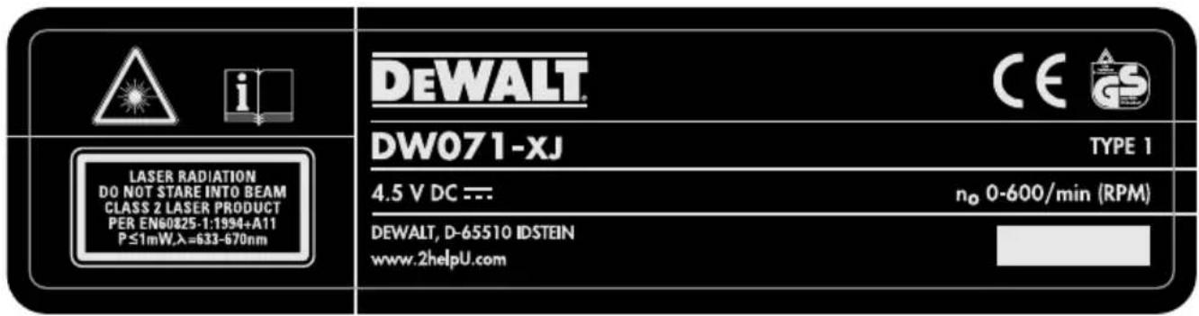
Labels on tool
For a complete reproduction of the labels attached to the tool, refer to the summary in the back of the manual. The labels on the tool show the following pictographs:

Read instruction manual before use

Laser warning

Bump warning
Package contents
The package contains:
1 Rotary laser
1 Wall mount/base
1 Target card
1 Pair of glasses
3 LR14 (D) batteries
1 Kitbox
1 Instruction manual
• Take the time to thoroughly read and understand this manual prior to operation.
Description (fig. A)
The rotary laser DW071 has been designed to project laser lines to aid in professional applications. The tool can be used both inside and outside for horizontal (level) and vertical (plumb) alignment.
The tool can also produce a stationary laser dot that can be directed manually to establish or transfer a mark. The applications range from drop-ceiling installation and wall layout to foundation leveling and deck building.
1 Variable speed switch
2 Bump sensor reset button
3 Bump sensor activation button
4 Carrying handle
5 Leveling knob
6 Wall mount
7 Laser head rotation button
8 Rotary laser head
9 Front air level
10 Front level adjustment knob
11 Wall mount clamp
12 Wall mount clamp lock
13 Rack pinion wheel
14 Fitting knob
15 Battery compartment
16 Rack pinion locking knob
17 Side level adjustment knob
18 Side air level
Assembly and adjustment
Replacing batteries (fig. B)
The attachment uses batteries of type LR14 (D).
- Unscrew and remove the battery compartment cover (19).
- Replace the batteries (20). Make sure the new batteries are placed as indicated (21).
- Re-install the battery compartment cover.

When replacing batteries, always replace the complete set. Do not mix old batteries with new ones. Preferably use alkaline batteries.
Low battery indicator (fig. B)
The tool has been equipped with a low battery indicator (22) located on the control panel. The low battery indicator is lit while the tool is switched on. It will blink to indicate that the batteries need to be replaced and the tool will automatically shut down.
- Switch off the tool and remove the batteries as soon as the indicator blinks.
Setting up the tool (fig. C1 - C5)
The tool facilitates various set-ups, making it useful for several applications.
Mounting the tool to the wall mount (fig. C1)
The wall mount may also be used as a base to provide extra stability for the tool.
- Place the tool onto the wall mount as required for your application.
- Fit the tool to the wall mount by inserting the threaded pin (23) into one of the receptacles in the tool and tightening the knob (14).
Floor set-up (fig. C1)
- Place the tool on a relatively smooth and level surface.
- Adjust the tool for a level or plumb application.
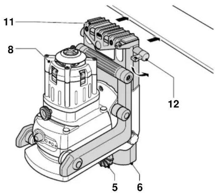
Wall set-up (fig. C2 - C5)
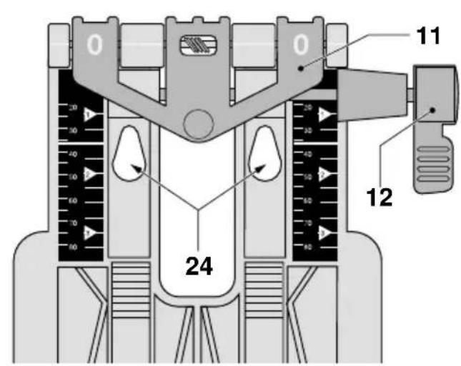
The tool is equipped with a wall mount (11) for mounting to a wall track to aid in drop ceiling installation and other specialty leveling projects (fig. C2).
- Mount the tool to the wall mount as described above.
- Turn the tool on its side with the wall mount clamp (11) in position for attachment to the wall track (fig. C3).
-
With the wall mount (6) facing the wall, turn the wall mount clamping lock (12) in the clockwise direction to open the clamp jaws.
-
Place the clamp jaws around the wall track and turn the wall mount clamping lock (12) in the anticlockwise direction to close the clamp jaws shut on the track.
- Ensure that the wall mount clamping lock (12) is securely locked.

Before attaching the tool to a wall track ensure that the track is properly secured to the wall.
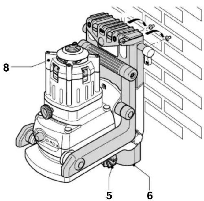
- Alternatively, the tool can be hung on the wall using the mounting holes (24) in the wall mount (fig. C2).
- Hold the tool at the desired position against the wall and mark the location of the two mounting holes on the wall (fig. C4).
- Drill a hole at each of the marked locations (required: 6 mm, approx. 35 mm deep).
- Insert a corresponding plug into each of the holes.
- Turn a screw into each of the plugs (required: 6 x 50 mm).
- Hang the tool on the screws.
- Adjust the leveling knob (5) to stabilize the tool when necessary.
- Adjust the tool for a level application.
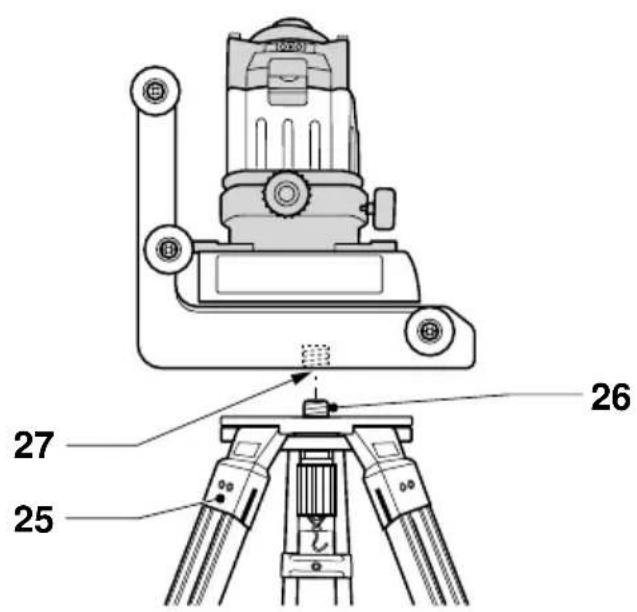
Tripod set-up (fig. C5)
The tool has been equipped with a tripod receptacle for mounting to the DE0736 tripod (optional) or any other tripod with the required ratings stated in the technical data.
- Place the tripod (25) on a relatively smooth and level surface.
- Mount the tool to the tripod by turning the threaded pin (26) into the receptacle (27).
- Adjust the tool for a level or plumb application.
Adjusting the tool (fig. D1 & D2)
The head can be set up either for level (fig. D1) or for plumb (fig. D2) applications.
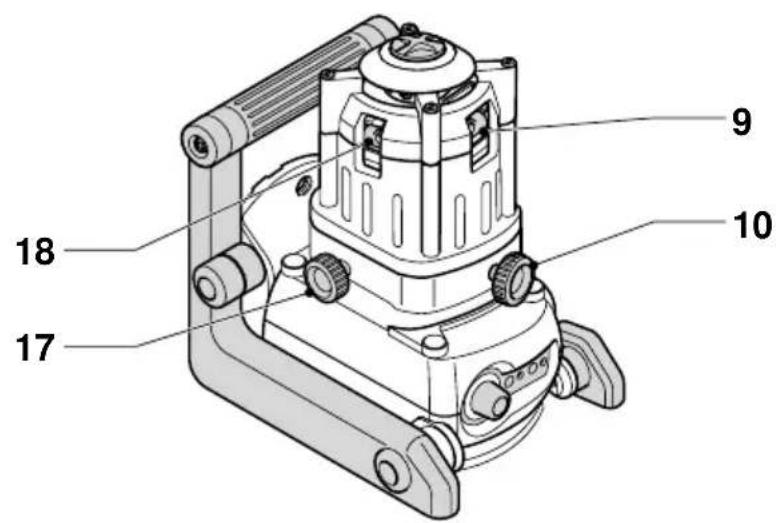
Level adjustment (fig. D1)
- Place the tool into the required position as shown.
- Read the air levels (9 & 18) to check whether the head is level.
- If adjustment is required, proceed as follows:
- Turn the level adjustment knobs (10 & 17) until the head is level. If you want to move the bubble to the right, turn the knob to the left, and vice-versa.
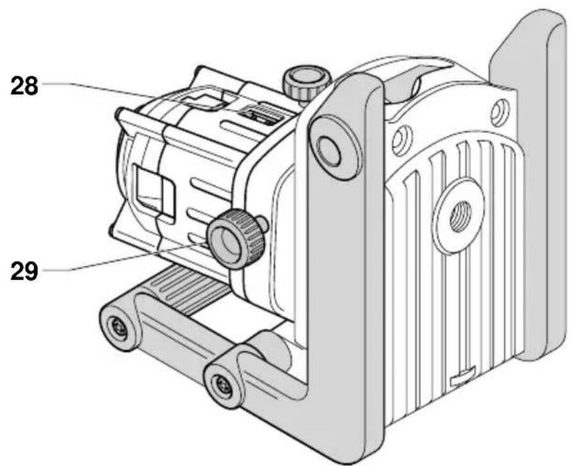
Plumb adjustment (fig. D2)
- Place the tool into the required position as shown.
- Read the air level (28) to check whether the tool is level.
- If adjustment is required, proceed as follows:
- Turn the level adjustment knob (29) until the tool is level. If you want to move the bubble to the right, turn the knob to the left, and vice-versa.
Aligning the laser line (fig. E1 & E4)
Level alignment
- With the tool switched on and the laser head rotating, align the laser line with the position mark.
- If adjustment is required, proceed as follows:
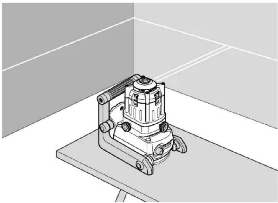
With tool in floor set-up (fig. E1):
- The tool can be placed on any sturdy object to obtain the required height.
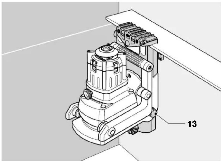
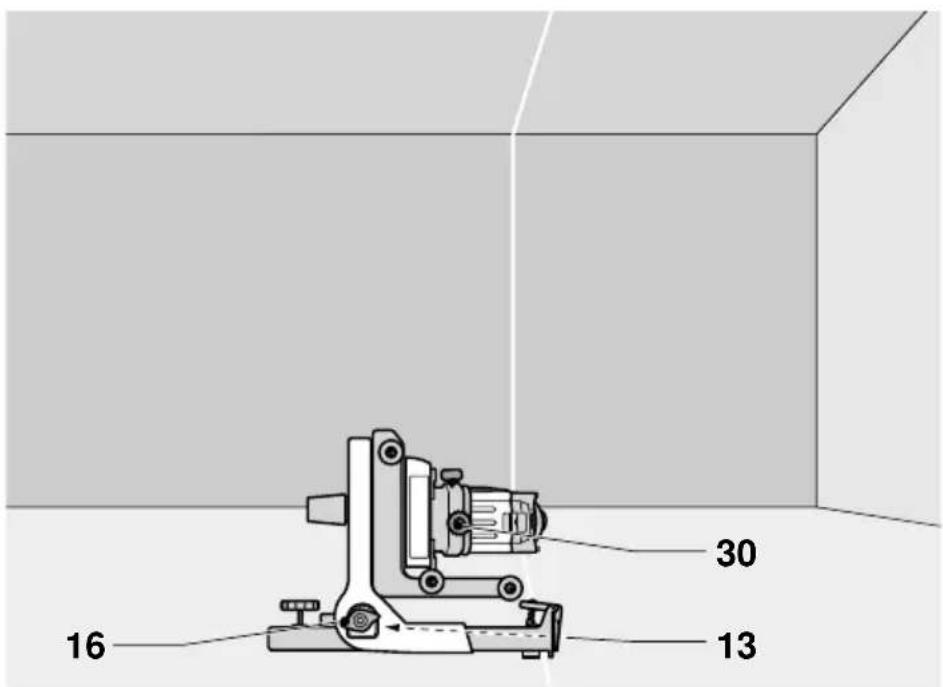
With tool in wall set-up (fig. E2):
- Loosen the locking knob (16) and adjust the rack pinion wheel (13) to set the tool to the correct position. Tighten the locking knob (16).
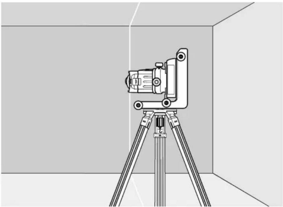
With tool in tripod set-up (fig. E3):
- Adjust the tripod to set the tool to the required height.
Plumb alignment (fig. E4)
- With the tool switched on and the laser head rotating, align the laser line with the position mark.
- If adjustment is required, proceed as follows:
- Move the tool as required. If the tool is attached to the wall mount, loosen the locking knob (16) and adjust the rack pinion wheel (13) to set the tool to the correct position. Tighten the locking knob (16) (fig. E4).
- Turn the level adjustment knob (30) until the head aligns with the position mark.
Instructions for use

Always observe the safety instructions and applicable regulations.
• Always mark the center of the laser line or dot.
- To increase working distance and accuracy, set up the tool in the middle of your working area.
- Make sure the tool has been set up securely.
- Extreme temperature changes cause movement of internal parts that may affect the accuracy of the tool. Regularly check the accuracy while using the tool under these circumstances.
- Regularly check whether the tool has registered a bump. When it has registered a bump, re-adjustment to balance or set-up may be required.
- If the tool has been dropped or has tipped over, have the laser head calibrated by a qualified repair agent.
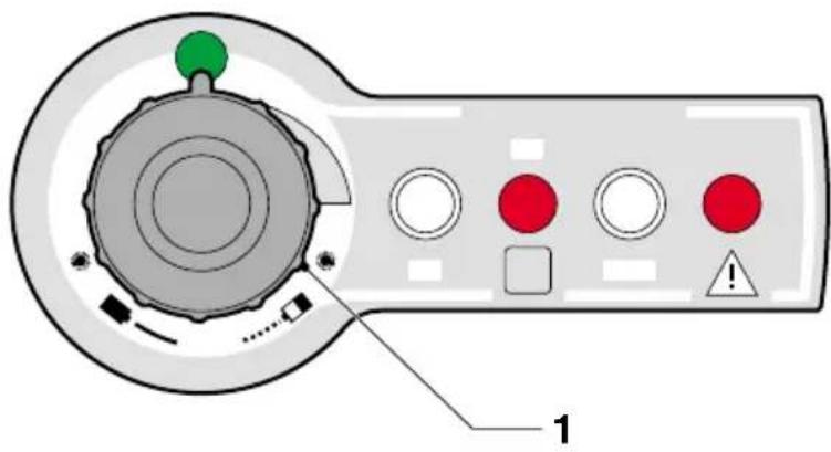
Switching on and off (fig. A)
- To switch the tool on, turn the switch (1) in the clockwise direction.
- To switch the tool off, turn the switch (1) in the anti-clockwise direction until it clicks into place.
Setting the rotation speed (fig. F)
The variable speed switch (1) is used to set the rotation speed, which determines the quality of the line. The rotary head remains stationary in the first quarter of the setting range.
- Turn the switch (1) as desired. Turning the switch in the clockwise direction increases the rotation speed. Turning the switch in the anti-clockwise direction decreases the rotation speed.
- For a stationary dot, set the switch in the first quarter of the setting range.
- For a bright line, set the switch to a slow rotation speed.
- For a solid line, set the switch to a fast rotation speed.
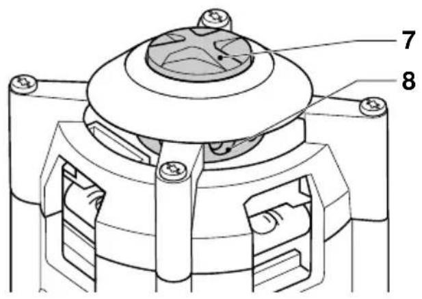
Manually rotating the laser head (fig. G)
In the stationary position, the laser head can be rotated manually.
- Depress the rotation button (7) and while keeping the button depressed turn it to rotate the laser head (8) into the required position.

Do not attempt to depress the rotation button while the laser head is rotating at a preset rotation speed.
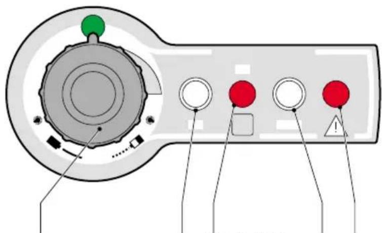
Bump sensor (fig. H)
The bump sensor responds to any bump that may affect the tool's balance or set-up. Once it registers a bump, the indicator light (32) goes blinking.
- To reset the bump sensor, press the button (2). The indicator (32) stops blinking.
Activating the bump sensor interruption With the bump sensor interruption activated, once a bump is registered the rotating laser head stops rotating while the laser beam starts flashing.
- To activate the bump sensor interruption, press the button (3). The indicator (31) lights up.
- To reset the bump sensor, press the button (2). The indicator (32) stops blinking and the tool returns to normal operation.
Tool aids (fig. I1 - I3)
Several aids have been supplied that might be helpful while operating the tool.
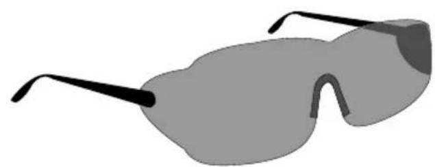
Laser enhancement glasses (fig. 11)
The red lens glasses improve the visibility of the laser beam under bright light conditions or over long distances. Providing best results indoors, the lens filters out ambient light and intensifies the projected dot or line. The glasses do not keep the laser beam from entering the eyes.

Never look into the laser beam directly with these glasses.
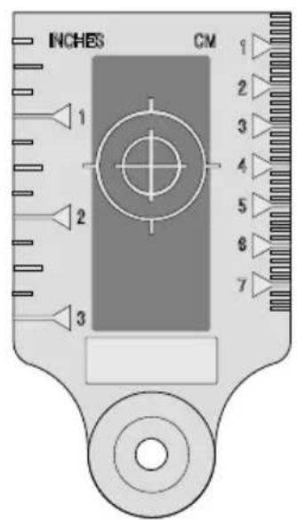
DE0730 Target card (fig. I2)
The target card locates and marks the laser beam as the beam crosses the card, thus enhancing the visibility of the projected line. The laser beam passes through the red plastic surface and is reflected by the reflective rear side of the card. Supporting easy use during plumb and level adjustment, the card is marked with inch and metric scales, and has magnets at the top to hold it to ceiling track or steel studs.
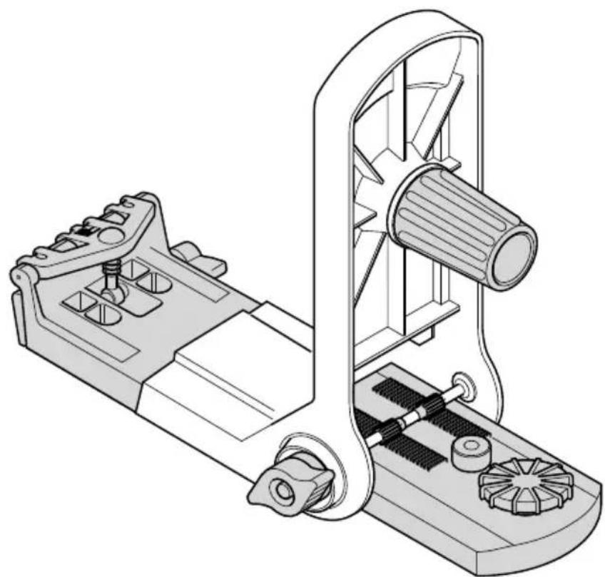
Wall mount (fig. 13)
The wall mount may also be used as a base to provide extra stability for the tool.
Optional accessories
Consult your dealer for further information on the appropriate accessories.
These are:
- DE0732 Digital laser detector with clamp
- DE0734 Grade rod
- DE0736 Tripod
Maintenance
Your DEWALT Power Tool has been designed to operate over a long period of time with a minimum of maintenance. Continuous satisfactory operation depends upon proper tool care and regular cleaning.
Field calibration check
The field calibration checks must be performed securely and accurately to make a correct diagnosis. Whenever an error is registered, have the tool calibrated by a qualified repair agent.

Always have the laser head calibrated by a qualified repair agent.
Tilt error checks
The following checks are performed to check the calibration of laser head for level alignment.
- Place the tool in an area midway between two vertical surfaces that are about 30 m away from each other.
- With the tool in a tripod set-up, adjust the head for a level application.
- To perform a quick check, read the front and rear air levels. After one of the air levels has been adjusted they should both be level. If the other air level is not level, the laser head must be calibrated.
To perform a front-to-back tilt error check:
- Position the tool so that it is aimed front-to-back toward the vertical surfaces.
- Switch on the tool with the laser head rotating.
- Mark the centre of the laser beam on each of the surfaces.
- Switch off the tool and rotate it 180^ so that it is aimed front to back the other way around.
- Switch on the tool with the laser head rotating and once again mark the centre of the laser beam on each of the surfaces. Switch off the tool.
-
Measure the difference between the marks on both surfaces. The difference between the marks on the one surface must equal the difference between the marks on the other surface.
-
If the difference between the marks is 6.35 mm or less, the laser head is properly calibrated.
- If the difference between the marks is more than 6.35 mm, the laser head must be calibrated.
To perform a side-to-side tilt error check:
- Position the tool so that it is aimed side-to-side toward the vertical surfaces.
- Following the same procedure as described above, mark the centre of the laser beam on each of the surfaces with the tool in this position, after which the tool is rotated 180^ to mark the centre of the laser beam once again.
- Measure the difference between the marks on both surfaces. The difference between the marks on the one surface must equal the difference between the marks on the other surface.
- If the difference between the marks is 6.35 mm or less, the laser head is properly calibrated.
- If the difference between the marks is more than 6.35 mm, the laser head must be calibrated.
Cone error check
The following check is performed to check the calibration of laser beam relative to the laser head.
- Place the tool in an area at about 7.5 m from a vertical surface.
- Adjust the head for a level application.
- To perform a quick check, switch on the tool with the laser head rotating. The tool should produce a single line. If the tool produces a double line, the laser head must be calibrated.
- Switch on the tool with the laser head stationary.
- Rotate the head so that the laser dots appear on the vertical surface.
- Mark the vertical position of the centre of each of the laser beams. Switch off the tool.
• Measure the difference between the marks. - If the difference between the marks is 2.4 mm or less, the laser head is properly calibrated.
- If the difference between the marks is more than 2.4 mm, the laser head must be calibrated.
Plumb error check
The following check is performed to check the calibration of laser head for plumb alignment.
- Place the tool in an area at about 7.5 m from a vertical surface.
- With the tool in a tripod set-up, adjust the head for a plumb application.
- Hang a plumb bob from the vertical surface.
- Switch the tool on with the laser head rotating.
- Align the laser line with the plumb bob string.
- If the laser line aligns with the plumb bob string, the laser head is properly calibrated.
- If the laser line does not align with the plumb bob string, the laser head must be calibrated.

Cleaning
- Remove the batteries before cleaning your power tool.
- Keep the ventilation slots clear and regularly clean the housing with a soft cloth.
- When necessary, clean the lens using a soft cloth or a cotton bud soaked in alcohol. Do not use any other cleaning agents.
Environment

Batteries
- When disposing batteries, think of the protection of the environment. Check with your local authorities for an environmentally safe way of battery disposal.
Unwanted tools
Take your tool to an authorised DEWALT repair agent where it will be disposed of in an environmentally safe way.
GUARANTEE
- 30 DAY NO RISK SATISFACTION GUARANTEE If you are not completely satisfied with the performance of your DEWALT tool, simply return it within 30 days, complete as purchased, to the point of purchase, for a full refund or exchange. Proof of purchase must be produced.
• ONE YEAR FREE SERVICE CONTRACT •
If you need maintenance or service for your DEWALT tool, in the 12 months following purchase, it will be undertaken free of charge at an authorized DEWALT repair agent. Proof of purchase must be produced. Includes labour and spare parts for Power Tools. Excludes accessories.
• ONE YEAR FULL WARRANTY •
If your DEWALT product becomes defective due to faulty materials or workmanship within 12 months from the date of purchase, we guarantee to replace all defective parts free of charge or, at our discretion, replace the unit free of charge provided that:
• The product has not been misused.
• Repairs have not been attempted by unauthorized persons.
• Proof of purchase date is produced.
This guarantee is offered as an extra benefit and is additional to consumers statutory rights.
For the location of your nearest authorized DEWALT repair agent, please use the appropriate telephone number on the back of this manual. Alternatively, a list of authorized DEWALT repair agents and full details on our after-sales service are available on the Internet at www.2helpU.com.
LASER ROTATIF DW071
Félicitations!
TUV Rheinland of North America
File Number E2071161.02-A1
L'emballage contient:
Support mural (fig. 13)
TUV Rheinland of North America
File Number E2071161.02-A1
Director Engineering and Product Development Horst Großmann

DEWALT, Richard-Klinger-Straße 40, D-65510, Idstein, Tyskland
Generelt
1 Bryter for variabelt turtall
TUV Rheinland of North America
File Number E2071161.02-A1
Director Engineering and Product Development Horst Großmann

TUV Rheinland of North America
File Number E2071161.02-A1
Director Engineering and Product Development Horst Großmann

Danmark DEWALT Tlf: 70 20 15 30
| Hejrevang 26 B Fax: 48 14 13 993450 Allerød www.dewalt-nordic.com |
| Calpe House Rock Hill |
| Black Rock, Co. Dublin |
Tel: 00353-2781800
| Fax: 00353-2781811 |
Italia DEWALT
United Kingdom DEWALT
| 210 Bath RoadSlough, Berks SL1 3YD |
Tel: 01753-56 70 55
| Fax: 01753-57 21 12 |