DCE089R - Laser pointer DEWALT - Free user manual and instructions
Find the device manual for free DCE089R DEWALT in PDF.

| Brand | DeWalt |
| Model | DCE089R |
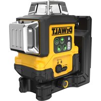
| Product type | 3-beam 360° rotary laser level |
| Light source | Laser diodes (red) |
| Wavelength | 620 – 680 nm |
| Laser class | 2 |
| Laser power | ≤ 1.50 mW per beam |
| Operating range without detector | 20 m |
| Range with detector | 50 m |
| Leveling accuracy | ± 3 mm per 10 m |
| Plumb accuracy | ± 3 mm per 10 m |
| Power supply | 4 AA batteries (1.5 V) or 10.8 V DeWalt rechargeable battery pack |
| Operating temperature | -10 °C to 50 °C |
| Storage temperature | -20 °C to 60 °C |
| Protection rating | IP65 |
| Maintenance | Clean with a soft, dry cloth. Do not use solvents. |
| Safety | Class 2 laser product. Do not stare directly at the beam. Avoid eye exposure. |
| Spare parts and repairability | No user-serviceable parts. Do not disassemble. Contact an authorized service center. |
| Warranty | 1 year limited |
| Included accessories | Pivoting magnetic mount, ceiling bracket |
| Self-leveling | Yes, range of ±4° |
| Low battery indicator | Yes, flashing LED |
| Detector compatibility | Yes, for extended range |
| Leveling angle | 360° horizontal, 360° vertical (3 beams) |
Frequently Asked Questions - DCE089R DEWALT
User questions about DCE089R DEWALT
0 question about this device. Answer the ones you know or ask your own.
Ask a new question about this device
Download the instructions for your Laser pointer in PDF format for free! Find your manual DCE089R - DEWALT and take your electronic device back in hand. On this page are published all the documents necessary for the use of your device. DCE089R by DEWALT.
USER MANUAL DCE089R DEWALT
natural_image
Line drawing of a DeWALT electric shock absorber device (no text or symbols on body)Figures
natural_image
Close-up of a black electronic device with two circular holes and a labeled section marked 'H', no readable text or symbols present.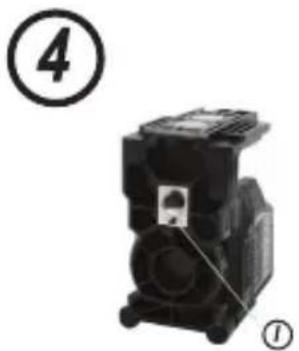
natural_image
Black industrial electrical component with labeled parts (4 and 1), no visible text or symbols on the main body.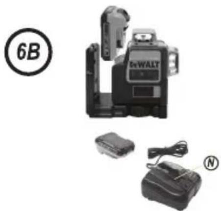
natural_image
Product photo of a DeWALT digital camera with attached battery and charging module (no visible text or symbols)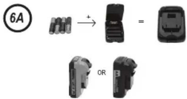

1
2

1
2
Figures

10
1
2
3
Notes
Contents
• Safety
- Product Overview
- Batteries and Power
- Operation
• Accuracy Check and Calibration
- Specifications
User Safety
Definitions: Safety Guidelines
The definitions below describe the level of severity for each signal word. Please read the manual and pay attention to these symbols.

DANGER: Indicates an imminently hazardous situation which, if not avoided, will result in death or serious injury.

WARNING: Indicates a potentially hazardous situation which, if not avoided, could result in death ofious injury.

CAUTION: Indicates a potentially hazardous situation which, if not avoided, may result in minor or moderate injury.
NOTICE: Indicates a practice not related to personal injury which, if not avoided, may result in property damage.
If you have any questions or comments about this or any dewalt tool, go to www.2helpU.com on the Internet.

WARNING:
Read and understand all instructions. Failure to follow the warnings and instructions may result in electric shock, fire and/or serious injury.
SAVE THESE INSTRUCTIONS

WARNING:
Laser Radiation Exposure. Do not disassemble or modify the laser level. There are no user serviceable parts inside. Serious eye injury could result.

WARNING:
Hazardous Radiation. Use of controls or adjustments or performance of procedures other than those specified herein may result in hazardous radiation exposure.
The label on your tool may include the following symbols.
V volts
mW milliwatts

laser warning symbol
nm wavelength in nanometers
2 Class 2 Laser
Warning Labels
For your convenience and safety, the following labels are on your laser.


WARNING: To reduce the risk of injury, user must read instruction manual.
WARNING: LASER RADIATION. DO NOT STARE INTO BEAM. Class 2 Laser Product
- Do not operate the laser in explosive atmospheres, such as in the presence of flammable liquids, gases, or dust. Power tools create sparks which may ignite the dust or fumes.
- Use the laser only with the specifically designated batteries. Use of any other batteries may create a risk of fire.
- Store idle laser out of reach of children and other untrained persons. Lasers are dangerous in the hands of untrained users.
- Do not use tool if switch does not turn it on or off. Any tool that cannot be controlled with the switch is dangerous and must be repaired.
- Do not use optical tools such as a telescope or transit to view the laser beam. Serious eye injury could result.
- Do not place the laser in a position which may cause anyone to intentionally or unintentionally stare into the laser beam. Serious eye injury could result.
- Do not position the laser near a reflective surface which may reflect the laser beam toward anyone's eyes. Serious eye injury could result.
- Turn the laser off when it is not in use. Leaving the laser on increases the risk of staring into the laser beam.
GB
- Do not modify the laser in any way. Modifying the tool may result in hazardous laser radiation exposure.
- Do not operate the laser around children or allow children to operate the laser. Serious eye injury may result.
- Do not remove or deface warning labels. If labels are removed user or others may inadvertently expose themselves to radiation.
- Position the laser securely on a level surface. Damage to the laser or serious injury could result if the laser falls.
Laser Information
The DCE089G, DCE089R 3-Beam 360° Line Laser and the DCE0811G, DCE0811R 2-Beam 360° Line Laser are Class 2 laser products. The lasers are self-leveling laser tools that can be used for horizontal (level) and vertical (plumb) alignment projects.

WARNING:
Read and understand all instructions. Failure to follow all instructions listed below may result in electric shock, fire and/or serious personal injury.
Work Area
- Keep your work area clean and well lit. Cluttered benches and dark areas invite accidents.
- Do not operate laser tools in explosive atmospheres, such as in the presence of flammable liquids, gases, or dust.
- Keep children and bystanders away while operating a laser tool. Distractions can cause you to lose control.
Electrical Safety
Use battery operated tool only with the specifically designed batteries. Use of any other batteries may create a risk of fire.
Product Overview

WARNING:
Never modify the tool or any part of it. Damage to the laser or personal injury could result.
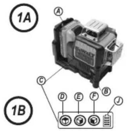
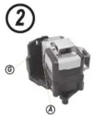
Figure 2 - Battery Interface A
Figure 1A - Pendulum Lock B
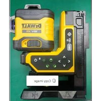
Figure 1B - Keypad ©
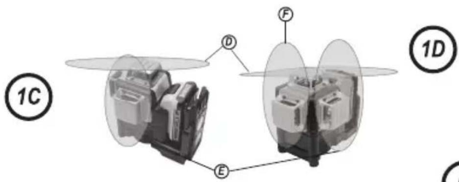
Figure 1B - ON/OFF button: horizontal laser line D
Figure 1B - ON/OFF button: side laser line Ⓔ
Figure 1B - ON/OFF button: front vertical laser line (DCE089R/G only)
Figure 2 - Magnetic pivot bracket Ⓖ
Figure 4 - Tripod thread fitting (1/4 - 20 & 5/8 - 11)
Figure 1B - Battery level indicator ⏻
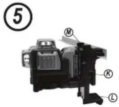
Figure 5 - Ceiling Mount Clamp Ⓚ
Figure 5 - Ceiling Mount Ⓛ
Figure 5 - Screw Hole Ⓜ
Batteries and Power
This tool is powered by the following DeWALT 10.8V Battery packs: DCB120, DCB127 or may also be powered using the DEWALT AA Starter pack which can carry four AA batteries. Note: The AA starter pack is recommended only for use with the red laser.
Battery Installation and Removal
Using the AA Starter Pack:

CAUTION:
The AA starter pack is designed specifically for use only with the DeWALT 10.8V compatible laser products and cannot be used with any other tools Do not attempt to modify the product.
To install batteries:
- Lift up the battery compartment cover as shown in Figure 6A.
- Insert four fresh AA batteries in the compartment, placing the batteries according to (+) and (−) on the inside of the compartment.
- Install the AA starter Battery pack as shown in Figure 6B.
Using the 10.8V Rechargeable Pack:
Install the 10.8V DeWALT Battery pack as shown in Figure 6B.

WARNING: Batteries can explode, or leak, and can cause injury or fire. To reduce this risk:
- Carefully follow all instructions and warnings on the battery label and package and accompanying Battery Safety Leaflet.
- Always insert batteries correctly with regard to polarity (+ and -), marked on the battery and the equipment.
- Do not short battery terminals.
- Do not charge disposable batteries.
- Do not mix old and new batteries. Replace all of them at the same time with new batteries of the same brand and type.
- Remove dead batteries immediately and dispose of per local codes.
- Do not dispose of batteries in fire.
- Keep batteries out of reach of children.
- Remove batteries when the device is not in use
- Use only the charger specified for your rechargeable battery pack.
Personal Safety
- Stay alert, watch what you are doing and use common sense when operating a laser tool. Do not use tool while tired or under the influence of drugs, alcohol, or medication. A moment of inattention while operating power tools may result in serious personal injury.
- Use personal protective equipment. Always wear eye protection. Protective equipment such as dust mask, non-skid safety shoes, hard hat, or hearing protection used for appropriate conditions will reduce personal injuries.
Service
- Tool service must be performed only by qualified repair personnel. Service or maintenance performed by unqualified personnel could result in a risk of injury.
- When servicing a tool, use only identical replacement parts. Follow instructions in the Maintenance section of this manual. Use of unauthorized parts or failure to follow Maintenance Instructions may create a risk of electric shock or injury.
To locate your nearest DeWALT service center go to http://www.2helpU.com on the Internet.
Operating Tips
- Use only new, high-quality, name brand AA batteries or specified rechargeable DEWALT10.8V Li-Ion pack for best results.
- Ensure batteries are in good working condition. If the low battery red indicator light is flashing, the batteries need replacement.
- To extend battery life, turn laser off when not working with or marking the beam.
- To ensure the accuracy of your work, check to make sure your laser is calibrated often. See Field Calibration Check.
- Before attempting to use the laser, make sure it is positioned securely, on a smooth, flat surface.
• Always mark the center of the beam created by the laser. - Extreme temperature changes may cause movement of internal parts that can affect accuracy. Check your accuracy often while working. See Field Calibration Check.
- If the laser has been dropped, check to make sure your laser is still calibrated. See Field Calibration Check.
- Place the laser on a smooth, flat, stable surface that is level in both directions.
Low Battery Indication
The DCE089G, DCE089R, DCE0811G and DCE0811R lasers are equipped with a battery gauge as shown in Figure 1B. The battery gauge indicates remaining power with each LED representing 25%. The bottom LED will illuminate and blink indicating that the level is low (below 12.5%) and the batteries need to be replaced. The laser may continue to operate for a short time while the batteries continue to drain, but the beam(s) will quickly dim. After fresh batteries are installed and the laser is turned on again, the laser beam(s) will return to full brightness and the battery indicator level will indicate full capacity. (A flashing laser beam is not caused by low
GB
batteries; see Out of Tilt Range Indicator.) If all 4 LEDs on the battery meter LEDs continuously flash this does not indicate a low battery; see "The Battery Meter LEDs Flash" under Troubleshooting.
Operation
To Turn the Lasers On and Off (See Figure 1)
With the laser off, place it on a flat level surface. Slide the Pendulum Lock switch Ⓑ to the Unlocked/ON position. The DCE089G/R model has three ON/OFF buttons on the keypad ⓒ one for a horizontal laser line Ⓓ, one for a side vertical laser line Ⓔ and one for a front vertical laser line Ⓕ (DCE089G/R only). The DCE0811G/R has two lines -a horizontal line and side vertical line. Each laser line is powered on by pressing its ON/OFF button on the keypad. The laser lines can be powered one at a time or all at the same time. Pressing the ON/OFF keys again turns the laser lines off. Slide the Pendulum Lock switch to the OFF/Locked position when the laser is not in use. If the pendulum lock switch is not placed in the lock position all 4 LEDs will continuously flash on the Battery Meter.
Using the Lasers
Out of LEVEL Range Indicator
The lasers are designed to self-level. If the laser has been tilted so much that it cannot self-level ( >4^ ), the laser beam will flash. There are two flashing sequences associated with the out of level condition: (i) between 4^ and 10^ the beams flash with a constant blink cycle; (ii) at angles greater than 10^ the beams flash with a three blink cycle. When the beams flash THE LASER IS NOT LEVEL (OR PLUMB) AND SHOULD NOT BE USED FOR DETERMINING OR MARKING LEVEL OR PLUMB. Try repositioning the laser on a more level surface.
Using the Pivot Bracket (See figure ②)

WARNING:
Position the laser and/or wall mount on a stable surface. Serious personal injury or damage to the laser may result if the laser falls.:
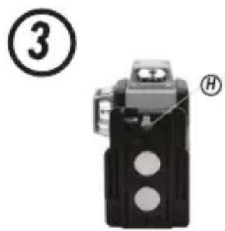
The laser has a magnetic pivot bracket G permanently attached to the unit. This bracket allows the unit to be mounted to any upright surface made of steel or iron. Common examples of suitable surfaces include steel framing studs, steel door frames and structural steel beams. The bracket also has a keyhole slot H allowing the unit to be hung from a nail or screw on any kind of surface.
Using the Laser with the CEILING Mount (See Figure 5)
The laser ceiling mount L (if included) offers more mounting options for the laser. The ceiling mount has a clamp K at one end which can be fixed to a wall angle for acoustic ceiling installation. At each end of the ceiling mount is a screw hole M, allowing the ceiling mount to be attached to any surface with a nail or screw. Once the ceiling mount is secured, its steel plate provides a surface to which the magnetic pivot bracket G can be attached. The position of the laser can then be fine-tuned by sliding the magnetic pivot bracket up or down on the wall mount.
Using the Lasers with Accessories
The lasers are equipped with 1/4" - 20 and 5/8" - 11 female threads on the bottom of the unit. This thread is to accommodate current or future DeWALT accessories. Only use DeWALT accessories specified for use with this product. Follow the directions included with the accessory.

CAUTION:
The use of any other accessory not recommended for use with this tool could be hazardous.
If you need any assistance in locating any accessory, please contact your nearest DeWALT service center or go to www.2helpU.com on the Internet.
Leveling the Lasers
As long as the laser is properly calibrated, the laser is self-leveling. Each laser is calibrated at the factory to find level as long as it is positioned on a flat surface within average ±4^ of level. No manual adjustments are required.
Maintenance
- To maintain the accuracy of your work, check the laser often to make sure it is properly calibrated. See Field Calibration Check.
- Calibration checks and other maintenance repairs may be performed by DeWALT service centers.
- When not in use, store the laser in the kit box provided. Do not store your laser at temperatures below -20 °C (-5 °F) or above 60 °C (140 °F).
- Do not store your laser in the kit box if the laser is wet. The laser should be dried first with a soft dry cloth prior to storage.
Cleaning
Exterior plastic parts may be cleaned with a damp cloth. Although these parts are solvent resistant, NEVER use solvents. Use a soft, dry cloth to remove moisture from the tool before storage.
Accuracy Check and Calibration
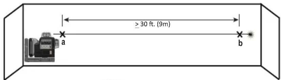
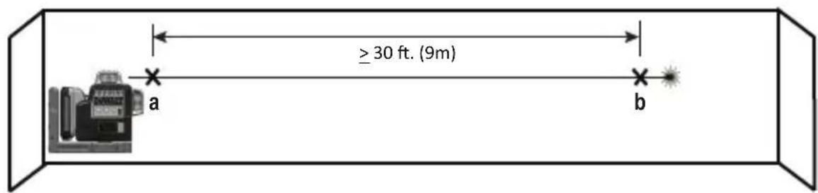
Checking Accuracy – Horizontal Beam - Scan Direction (See figure ⑦)
Checking the horizontal scan calibration of the laser requires two walls 9m (30') apart. It is important to conduct a calibration check using a distance no shorter than the distance of the applications for which the tool will be used.
- Place the laser on a smooth, flat, stable surface that is level in both directions, with the laser facing straight ahead toward the opposing wall (0 degree position).
- Turn on the laser's horizontal beam and pivot the laser toward the opposite end of the wall and approximately parallel to the adjacent wall (Figure ⑦#1).
- Mark the center of the beam at two locations (a, b) at least 30' (9m) apart.
- Pivot the laser 180° on the bracket, and mark the horizontal beam position on the opposing wall ⓒ (Figure 7 #2).
- Measure the vertical distance between ⓑ and Ⓒ . If the measurement is greater than the values shown below, the laser must be serviced at an authorized service center.
| Distance Between Walls | Allowable Distance Between ⓑ and Ⓒ |
| 9 m (30') 6.0 mm (1/4") | |
| 12 m (40') 8.0 mm (5'16") | |
| 15 m (50') 10.0 mm (13/32") |
- Rotate the laser 90° and repeat the test.
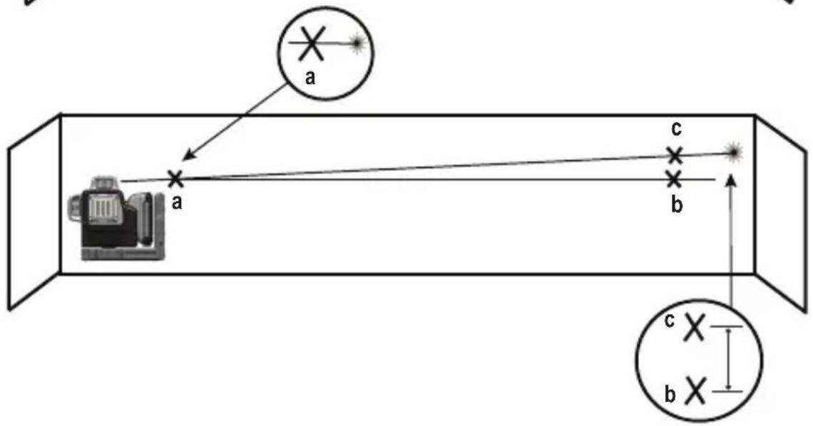
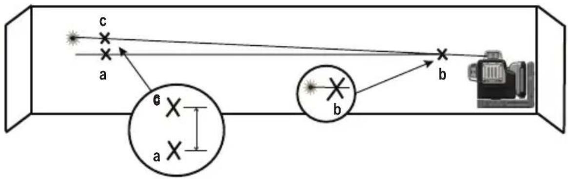
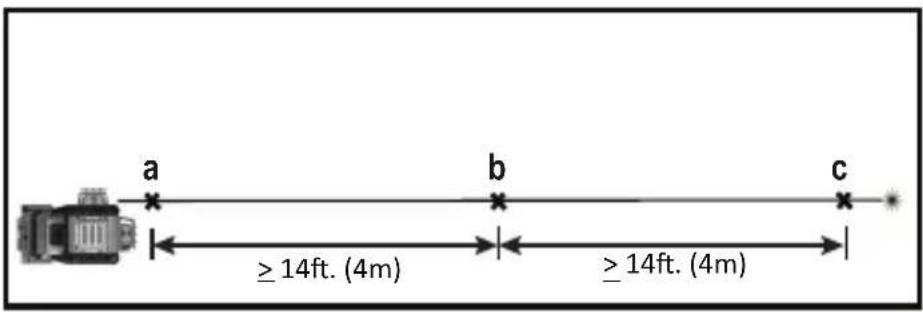
Checking Accuracy – Horizontal Beam - Pitch Direction (See figure 8)
Checking the horizontal pitch calibration of the laser requires a single wall at least 30' (9m) long. It is important to conduct a calibration check using a distance no shorter than the distance of the applications for which the tool will be used.
- Place the laser on a smooth, flat, stable surface that is level in both directions and against the end of a 30' (9m) wall.
- Turn on the laser's horizontal beam and pivot the laser toward the opposite end of the wall and approximately parallel to the adjacent wall (Figure 8 #1).
- Mark the center of the beam at two locations (a, b) at least 30' (9m) apart.
- Reposition the laser to the opposite end of the wall (Figure 8 #2).
- Turn on the laser's horizontal beam and pivot the laser back toward the first end of the wall and approximately parallel to the adjacent wall.
- Adjust the height of the laser so that the center of the beam is aligned with the nearest mark ⓑ.
- Mark the center of the beam c directly above or below the farthest mark a.
- Measure the distance between and . If the measurement is greater than the values shown below, the laser must be serviced at an authorized service center.
| Distance Between Walls | Allowable Distance Between a and c |
| 9 m (30') 6.0 mm (1/4") | |
| 12 m (40') 8.0 mm (5'16") | |
| 15 m (50') 10.0 mm (13/32") |
GB
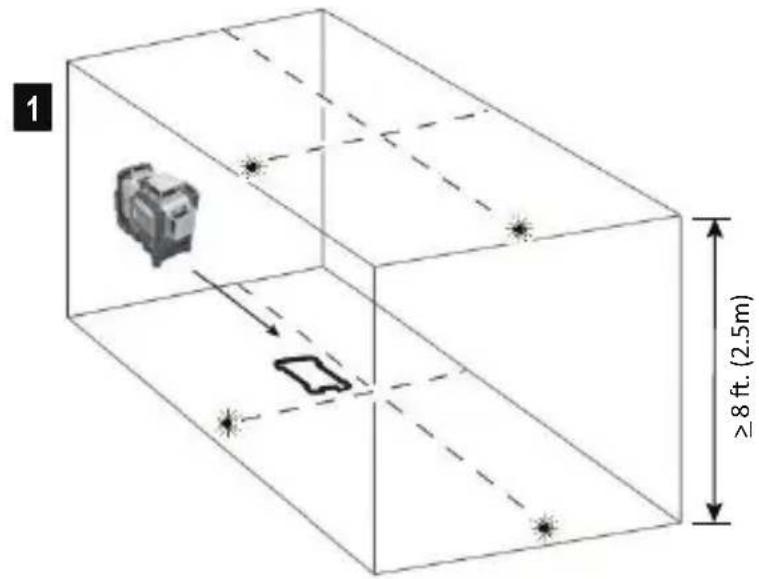
Checking Accuracy – Vertical Beam (See Figure 9)
Checking the vertical (plumb) calibration of the laser can be most accurately done when there is a substantial amount of vertical height available, ideally 30' (9m), with one person on the floor positioning the laser and another person near a ceiling to mark the position of the beam. It is important to conduct a calibration check using a distance no shorter than the distance of the applications for which the tool will be used.
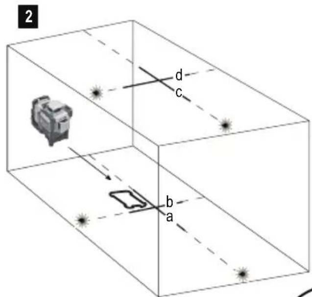
- Place the laser on a smooth, flat, stable surface that is level in both directions and turn on both vertical beams (Figure 9 #1).
- Mark two short lines where the beams cross (a, b) and also on the ceiling c, d. Always mark the center of the beams' thickness (Figure 9 #2).
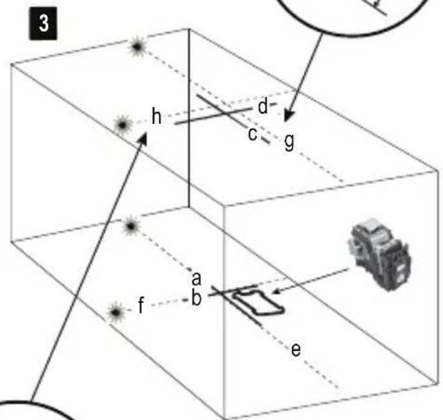
- Pick up and rotate the laser 180^ , and position it so the beams line up with the marked lines on the level surface (e, f) (Figure 9#3).
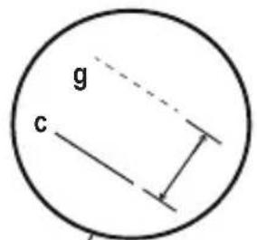
- Mark two short lines where the beams cross on the ceiling , .
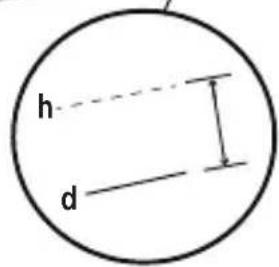
- Measure the distance between each set of marked lines on the ceiling (c, g and d, h). If the measurement is greater than the values shown below, the laser must be serviced at an authorized service center.
| Ceiling Height | Allowable Distance Between Marked Lines |
| 2.5 m (8') 1.5 mm (1/16") | |
| 3 m (10') 2.0 mm (3/32") | |
| 4 m (14') 2.5 mm (1/3") | |
| 6 m (20') 4 mm (5/32") | |
| 9 m (30') 6 mm (1/4") |
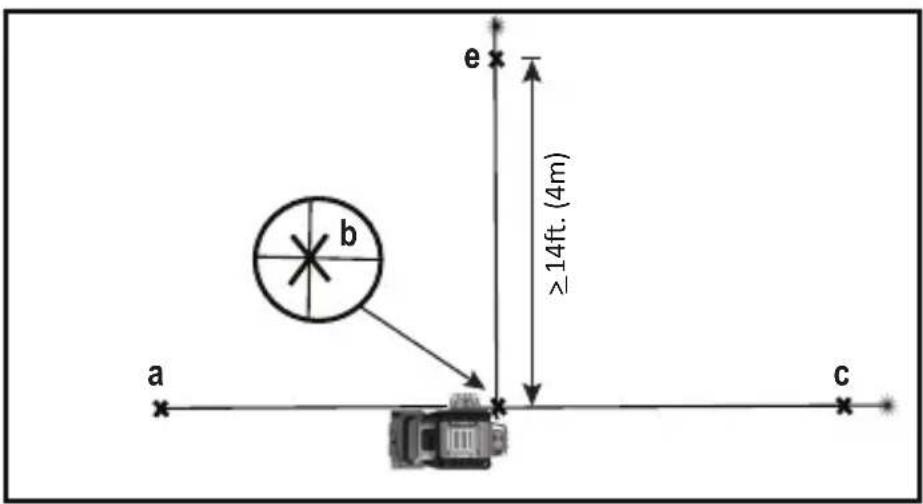
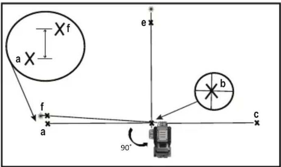
Checking 90° Accuracy Between Vertical Beams (DCE089R/G) (See Figure 10)
Checking 90° accuracy requires an open floor area at least 10m x 5m (33' x 18'). Refer to Figure 10 for the position of the laser at each step and for the location of the marks made at each step. Always mark the center of the beams' thickness.
-
Set up the laser on a smooth, flat, stable surface that is level in both directions and turn on the side vertical beam.
-
Mark the center of the beam at three locations (a, b, c) along the side laser line. Mark b should be at the midpoint of the laser line (Figure 10 #1).
- Move the laser to mark ⓑ and turn on both vertical beams (Figure 10 #2).
- Position the beam crossing precisely at mark ⓑ, with the side beam aligned with mark ⓐ.
- Mark a location ⓔ along the front vertical beam at least 4m (14') away from the unit.
- Rotate the laser cross over mark b so that the beams pass through marks b and e (Figure 10#3).
- Mark the center of the beam directly above or below .
- Measure the distance between marks and . If the measurement is greater than the values shown below, the laser must be serviced at an authorized service center.
| Distance from a to b | Allowable Distance Between a & f |
| 4 m (14') 3.5 mm (5,32") | |
| 5 m (17') 4.5 mm (3,16") | |
| 6 m (20') 5.5 mm (7,32") | |
| 7 m (23') 6 mm (1/4') |
Troubleshooting
The Laser Does Not Turn On
- Make sure AA batteries (when used) are installed correctly according to (+) and (−) on the inside of the battery door.
- Make sure the batteries or rechargeable pack are in proper working condition. If in doubt, try installing new batteries.
- Make sure that the battery contacts are clean and free of rust or corrosion. Be sure to keep the laser level dry and use only new, high-quality, name brand batteries to reduce the chance of battery leakage.
- If the laser unit is heated above 50 °C (120 °F), the unit will not turn on. If the laser has been stored in extremely hot temperatures, allow it to cool. The laser level will not be damaged by pressing the on/off button before cooling to its proper operating temperature.
The Laser Beams Flash
The lasers are designed to self-level up to an average of 4^ in all directions. If the laser is tilted so much that the internal mechanism cannot level itself, the laser beams will flash indicating that the tilt range has been exceeded. THE FLASHING BEAMS CREATED BY THE LASER ARE NOT LEVEL OR PLUMB AND SHOULD NOT BE USED FOR DETERMINING OR MARKING LEVEL OR PLUMB. Try repositioning the laser on a more level surface.
The Laser Beams Will Not Stop Moving
The laser is a precision instrument. Therefore, if it is not positioned on a stable (and motionless) surface, the laser will continue to try to find level. If the beam will not stop moving, try placing the laser on a more stable surface. Also, try to make sure that the surface is relatively flat, so that the laser is stable.
The Battery Meter Leds Flash
When all 4 LEDs continuously flash on the Battery Meter this indicates that the unit has not been fully powered off using the Pendulum Lock switch Ⓑ. The Pendulum Lock switch should always be placed in the LOCKED/OFF position when the laser is not in use.
Accessories

WARNING:
Since accessories, other than those offered by DeWalt, have not been tested with this product, use of such accessories with this tool could be hazardous. To reduce the risk of injury, only DeWalt recommended accessories should be used with this product.
Using the Laser with Accessories
(See Figure 2), inset)
The laser is equipped with both 1/4 - 20 and 5/8 - 11 female threads (l) on the bottom of the unit. This thread is to accommodate current or future DeWALT accessories. Only use DeWALT accessories specified for use with this product. Follow the directions included with the accessory.
Service and Repairs
- Note: Disassembling the laser level(s) will void all warranties on the product.
To assure product SAFETY and RELIABILITY, repairs, maintenance and adjustment should be performed by authorized service centers. Service or maintenance performed by unqualified personnel may result in a risk of injury. To locate your nearest DeWALT service center go to www.2helpU.com on the Internet.
1 Year Limited Warranty
DeWalt will repair, without charge, any defects due to faulty materials or workmanship for one year from the date of purchase. This warranty does not cover part failure due to normal wear or tool abuse. For further detail of warranty coverage and warranty repair information, visit www.dewalt.com. This warranty does not apply to accessories or damage caused where repairs have been made or attempted by others. This warranty gives you specific legal rights and you may have other rights which vary in certain states or provinces.
In addition to the warranty, DeWALT tools are covered by our:
1 Year Free Service
DeWalt will maintain the tool and replace worn parts caused by normal use, free, any time during the first year after purchase.
30 DAY no risk satisfaction GUARANTEE
If you are not completely satisfied with the performance of your DeWalt Laser, for any reason, you can return it within 30 days from the date of purchase with a receipt for a full refund – no questions asked.
Free Warning Label Replacement:
If your warning labels ① become illegible or are missing, visit www.dewalt.com for a free replacement.
Laser Tool
| Light Source Laser diodes | ||
| Laser Wavelength 620 – 630 nm visible (RED) 510 – 530 nm visible (GREEN) | ||
| Laser Power ≤1.50 mW (each beam) CLASS 2 LASER PRODUCT | ||
| Working Range 20 m (±65') RED 35 m (±115') GREEN | ||
| 50 m with detector 50 m with detector | ||
| Accuracy (Plumb) ±3 mm per 10 m (±1/8" per 33') | ||
| Accuracy (Level): ±3 mm per 10 m (±1/8" per 33') | ||
| Indicators | ||
| Battery Low 1 x LED Flashing on Battery meter | ||
| Unit Not Powered Off With Pendulum Lock Switch | 4 x LED Flashing on Battery meter | |
| Flashing Laser Beams Tilt range exceeded/unit is not level | ||
| Power Source 4 AA (1.5V) size batteries (6V DC) or 10.8V Dewalt Battery Pack | ||
| Operating Temperature -10°C to 50°C (14°F to 122°F) | ||
| Storage Temperature -20°C to 60°C (-5°F to 140°F) | ||
| Humidity Maximum relative humidity 80% for temperatures up to 31°C (88°F)decreasing linearly to 50% relative humidity at 40°C (104°F) | ||
| Environmental | Water & Dust Resistant to IP65 | |
Notes
GB
Inhalt
D
Faisceau vertical (voir figure ⑨)
| Distanza tra le pareti | Distanza consentita tra ⓑ e Ⓒ |
| 9 m (30') 6,0 mm (1/4") | |
| 12 m (40') 8,0 mm (5'16") | |
| 15 m (50') 10,0 mm (13/32") |
| Distanza tra le pareti | Distanza consentita tra ^a e ^c |
| 9 m (30') 6,0 mm (1/4") | |
| 12 m (40') 8,0 mm (5'16") | |
| 15 m (50') 10,0 mm (13/32") |
Figura 1B - Botonera ©
WAARSCHUWING: Lees de
advarselssymbol for laser
Figur 1B - Knappsats ©
Figur 1B - PÅ/AV knapp: horisontell laserlinje D
Figur 1B - PÅ/AV knapp: sidolaserlinje Ⓔ
Figur 1B - PÅ/AV knapp: vertikal laserlinje fram (endast DCE089R/G) F
Figur 2 - Magnetisk vridkonsol Ⓖ
Figur 1B - tastatur ©
Figur 1B - PÅ/AV knapp: horisontal laserlinje D
Figur 1B - PÅ/AV knapp: side-laserlinje Ⓔ
Figur 1B - PÅ/AV knapp: front vertikal laserlinje (kun DCE089R/G)
Figur 2 - magnetisk roterende brakett Ⓖ
Figur 5A - stativgjengefeste (1/4 - 20 & 5/8-11)
100270392 - Rev C August 2017
Copyright © 2017 DEWALT
www.2helpU.com