SP600-24 - Battery charger DOMETIC - Free user manual and instructions
Find the device manual for free SP600-24 DOMETIC in PDF.

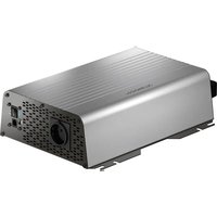
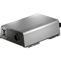
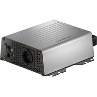
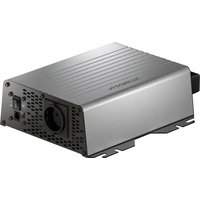
| Product type | Pure sine wave inverter |
| Brand | Dometic |
| Model | SP600-24 |
| Continuous output power | 600 W |
| Peak output power | 1500 W (a few seconds) |
| Output voltage | 230 V AC / 50 Hz ± 3 Hz |
| Input voltage | 24 V DC |
| No-load consumption | 210 mA |
| USB port | 5 V / 2.1 A |
| Dimensions (W x D x H) | 140 x 244.5 x 71 mm |
| Wave type | Pure sine |
| Galvanic isolation | Yes (isolated input/output) |
| Ventilation | Temperature-controlled |
| Protections | Short circuit, overload, overheat, reverse polarity |
| Soft start function | Yes |
| Remote control | Yes (via RJ11) |
| Low battery alarm | Yes |
| Internal fuses | 2 x 25 A (white) |
| Maintenance | Clean with a damp cloth, check connections |
| Warranty | Legal warranty |
Frequently Asked Questions - SP600-24 DOMETIC
User questions about SP600-24 DOMETIC
0 question about this device. Answer the ones you know or ask your own.
Ask a new question about this device
Download the instructions for your Battery charger in PDF format for free! Find your manual SP600-24 - DOMETIC and take your electronic device back in hand. On this page are published all the documents necessary for the use of your device. SP600-24 by DOMETIC.
USER MANUAL SP600-24 DOMETIC
natural_image
Technical line drawing of four different electric motors (no text or symbols present)SM400-12, SM600-12, SM600-24, SM1000-12, SM1500-12, SP400-12, SP600-12, SP600-24, SP1000-12, SP1000I-12, SP1500-12, SP1500I-12, SP1500-24, SP2000I-12, SP3000-12, SP3000-24
EN Inverter Operating manual....9
EN
3
natural_image
Technical line drawing of a server or electronic device with an inset showing a screwdriver inserted into a housing (no text or symbols present)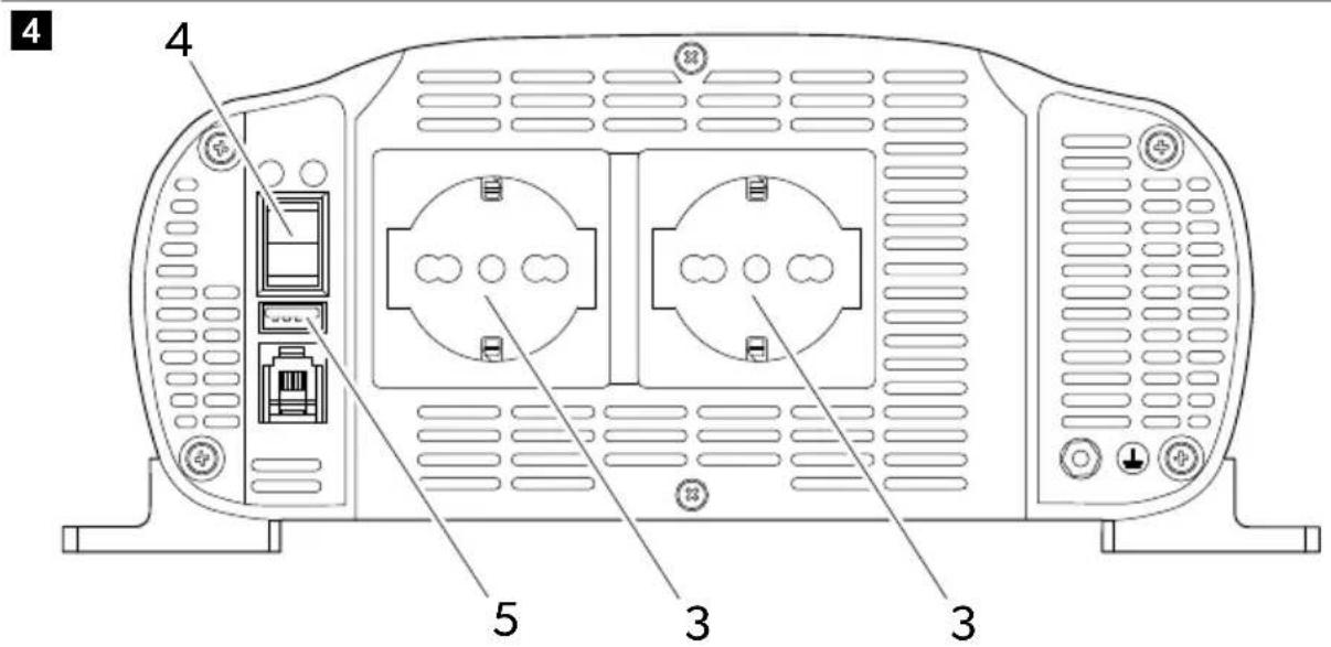
EN
natural_image
Technical line drawing of a cylindrical electronic device with internal ports and mounting feet (no text or symbols)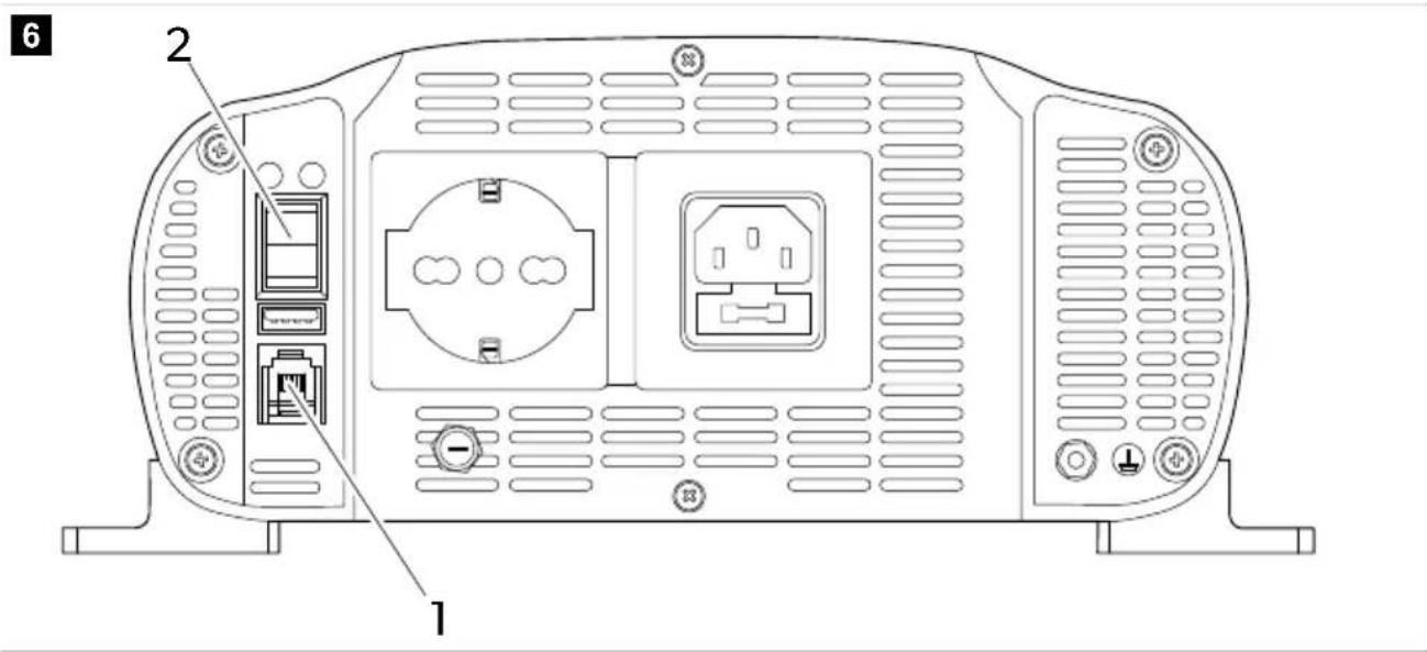
7

8
EN
11
Copyright
© 2023 Dometic Group. The visual appearance of the contents of this manual is protected by copyright and design law. The underlying technical design and the products contained herein may be protected by design, patent or be patent pending. The trademarks mentioned in this manual belong to Dometic Sweden AB. All rights are reserved.
English
1 Important notes....9
2 Explanation of symbols....9
3 Safety instructions....10
4 Scope of delivery....10
5 Intended use....17
6 Target group....11
7 Technical description....11
8 Before installation....12
9 Installation....13
10 Connecting the external mains power supply (SP1000I-12, SP1500I-12 and SP2000I-12 models).... 14
11 Connecting the remote control....14
12 Operation....15
13 Fuse replacement....15
14 Cleaning and maintenance....16
15 Disposal....16
16 Warranty....17
17 Technical data....17
1 Important notes
Please read these instructions carefully and follow all instructions, guidelines, and warnings included in this product manual in order to ensure that you install, use, and maintain the product properly at all times. These instructions MUST stay with this product.
By using the product, you hereby confirm that you have read all instructions, guidelines, and warnings carefully and that you understand and agree to abide by the terms and conditions as set forth herein. You agree to use this product only for the intended purpose and application and in accordance with the instructions, guidelines, and warnings as set forth in this product manual as well as in accordance with all applicable laws and regulations. A failure to read and follow the instructions and warnings set forth herein may result in an injury to yourself and others, damage to your product or damage to other property in the vicinity. This product manual, including the instructions, guidelines, and warnings, and related documentation, may be subject to changes and updates. For up-to-date product information, please visit documents.dometic.com.
2 Explanation of symbols

WARNING!
Indicates a hazardous situation that, if not avoided, will result in death or serious injury.

CAUTION!
Indicates a hazardous situation that, if not avoided, could result in minor or moderate injury.

NOTICE!
Indicates a hazardous situation that, if not avoided, could result in minor or moderate injury.
3 Safety instructions

WARNING! Failure to obey these warnings could result in death or serious injury.
- In event of fire, use a fire extinguisher which is suitable for electrical device.
- Do not operate the device if it is visibly damaged.

CAUTION! Failure to obey these warnings could result in death or serious injury.
- Installation, assembly, and wiring as well as all other work may only be performed by qualified electrical specialists. Inadequate repairs may cause serious hazards.
- Installation in potentially explosive areas such as rooms with inflammable liquids or gases is not permitted.
- Do not install or keep the device near flames or other heat sources (heating, direct sunlight, gas ovens etc.).
• Children shall not play with the appliance. - This appliance can be used by children aged from 8 years and above and persons with reduced physical, sensory or mental capabilities or lack of experience and knowledge if they have been given supervision or instruction concerning use of the appliance in a safe way and understand the hazards involved.

NOTICE! Indicates a situation that, if not avoided, can result in property damage.
- Check that the voltage specification on the data plate corresponds to that of the energy supply.
- Never immerse the device in water.
- Protect the device and cables against heat and moisture.
- Do not expose the device to rain.
- Make sure that the mounting surface is capable of supporting the weight of the device.
- Lay the cables so that they cannot be tripped over or damaged.
- Use ductwork or cable ducts if it is necessary to lay cables through metal panels or other panels with sharp edges.
4 Scope of delivery
| Description Quantity |
| Inverter 1 |
| Red power cable 1 |
| Black power cable 1 |
| Operating manual 1 |
5 Intended use
The device is intended to supply 230 V to connected appliances generated from 12 V or 24 V input voltage. The device is designed to be used in motorhomes, campervans and coaches.
The model line includes two types of devices:
- The SM400-12, SM600-12, SM600-24, SM1000-12 and SM1500-12 models are inverters with modified sinusoidal wave output.
- The SP400-12, SP600-12, SP600-24, SP1000-12, SP1500-12, SP1500-24, SP3000-12 and SP3000-24 models are inverters with pure sinusoidal wave output.
The SP1000I-12, SP1500I-12 and SP2000I-12 models are featuring an integrated priority function (IVT) and a fuse-protected input (IEC) socket for the external power supply connection.
This product is only suitable for the intended purpose and application in accordance with these instructions.
This manual provides information that is necessary for proper installation and/or operation of the product. Poor installation and/or improper operating or maintenance will result in unsatisfactory performance and a possible failure.
The manufacturer accepts no liability for any injury or damage to the product resulting from:
- Incorrect assembly or connection, including excess voltage
- Incorrect maintenance or use of spare parts other than original spare parts provided by the manufacturer
• Alterations to the product without express permission from the manufacturer - Use for purposes other than those described in this manual
Dometic reserves the right to change product appearance and product specifications.
6 Target group

The electrical power supply must be connected by a qualified electrician who has demonstrated skill and knowledge related to the construction and operation of electrical equipment and installations, and who is familiar with the applicable regulations of the country in which the equipment is to be installed and/or used, and has received safety training to identify and avoid the hazards involved.
7 Technical description
The device has two main circuit stages to convert the 12 V DC or 24 V DC input voltage to AC output voltage. The first stage consists of an isolated high frequency DC/DC converter to convert the 12 V DC or 24 V DC input voltage to an output voltage up to 400 V DC. The final stage consists of a H-bridge that converts the DC high voltage bus to 230 V AC voltage.
The device has the following main features:
- Low consumption.
- Galvanically isolated input and output for increased safety.
- Temperature-controlled fan speed for quiet operation.
- Integrated priority switch between external mains network and the battery.
- Ready for On/Off remote control.
EN
- Low battery voltage alarm.
- Low and high battery voltage shutdown.
- Overload shutdown.
- Protection against short-circuit, overtemperature, overload, and reverse polarity.
- Soft start function.
8 Before installation
Battery requirements
Battery type and size can strongly affect the performance of inverters. Therefore, the type of loads the inverter will be powering and the duration of use between recharging must be identified. To determine the minimum battery requirements for an application, do the following:
- Determine the wattage from the labels of each appliance to be used simultaneously from the inverter. Usually, power consumptions shown in watts. If it is shown in amps, multiply by the value by 230 V to determine the wattage.
- Estimate the number of hours the equipment will be in use before recharging of the battery.
- Calculate the total energy required in Wh (Watt hours) by multiplying the time determined above with the sum of wattage. Divide the result by 10 if the inverter input is 12 V, or by 20 if it is 24 V. The resulting value in Ah represents the power requirement of the application.

Note When possible, recharge the battery when about 50 % discharged or earlier. This gives the battery a much longer life cycle, opposed to only recharging it when it is deeply discharged.
Troubleshooting interference problems
Some inexpensive sound systems may emit a buzzing noise from the loudspeakers when operated from the inverter. This occurs because the power supply in the sound system does not adequately filter the modified sine wave produced by the inverter. The solution is to use a sound system that has a high quality power supply, or use a pure sine wave inverter. When the inverter is operating, it can interfere with television reception on some channels. If interference occurs, try the following:
- Make sure that the chassis ground screw of the inverter is connected to the ground of the vehicle.
- Make sure that the television antenna provides an adequate signal and the antenna cable is in good condition.
- Keep the cables between the battery and the inverter as short as possible, and twist them together to reduce the radiated emissions.
- Move the television as far away from the inverter as possible.
- Do not operate high power loads with the inverter when the television is on.
Ground leak protection (excluding the SP1000I-12, SP1500I-12 and SP2000I-12 models)

NOTICE! Damage hazard
For the safe operation of multiple appliances, it is essential that a circuit breaker (residual current circuit breaker) is built into the socket distribution circuit.
EN
The ground socket is designed for a safety system such as the residual current circuit breaker (RCCB). Connect residual current circuit breaker according to the following diagram:
fig. 1 on page 1
- Connect the phase (P1) and neutral (P2) output to the residual current circuit breaker input.
- Connect the inverter ground to one of the two wires connected to the residual current circuit breaker input.
- Connect the neutral and the phase output from the residual circuit breaker input to the appliances.
- Connect the ground of the inverter to the ground of the appliances.

NOTICE! Damage hazard
The diagram above refers to the connection of the inverter output only. The IEC connector of the external mains input must be connected to the circuit breaker output of the external mains power source.
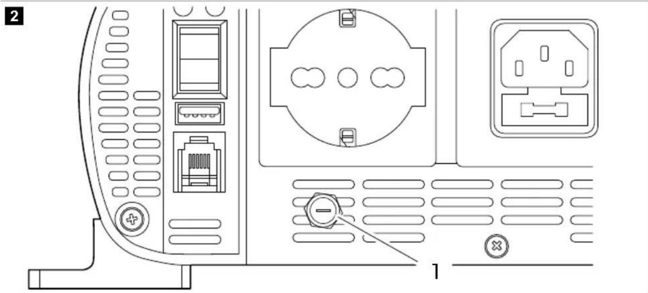
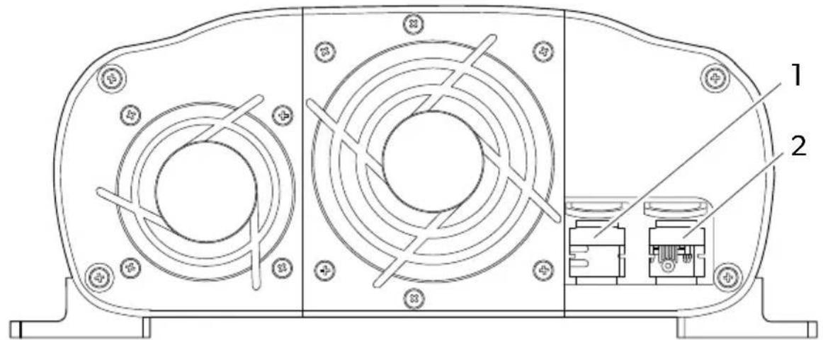
Ground leak protection (SP1000I-12, SP1500I-12 and SP2000I-12 models)
The output socket of the SP1000I-12, SP1500I-12 and SP2000I-12 models is protected with a fuse.
fig. 2 on page 1
To establish a TN type grounding arrangement, make sure the fuse is inserted into the fuse holder①
To establish a TE type grounding arrangement, make sure the fuse is not inserted into the fuse holder①
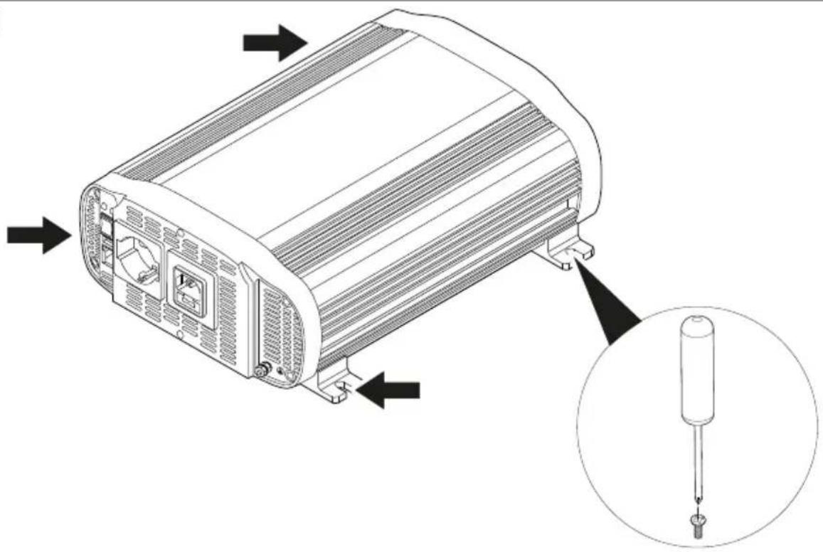
9 Installation

CAUTION! Damage hazard
Do not install the device close to heat sources or in not adequately ventilated places.

Note The device can be mounted in any position. If installed on a vertical surface, it is recommended to keep the long side parallel to the floor.

Note Install the device as close to the 12 V / 24 V power source as possible.
fig. 3 on page 2
- Mount the device by the four mounting flanges using appropriate screws.

NOTICE! Damage hazard
Before connecting the device, make sure that the power switch is in off position.

Note Use the supplied wires to connect the battery to the device. If the distance between the battery and the device exceeds 2 meters, increase the cross-section of the wire to reduce voltage drop and power losses.
fig. 4 on page 3
- Connect the negative terminal of the battery to the negative terminal of the inverter. ①
EN

NOTICE! Damage hazard
To protect the connected devices, install an inline fuse on the positive battery cable.
- Connect the positive terminal of the battery to the positive terminal of the inverter. ②
- Install the fuse into the inline fuse holder.

NOTICE! Damage hazard
Before connecting an appliance to the inverter, make sure it is turned off.
- Connect the 230 V appliance to an output socket. ③
- Turn the inverter on with On/Off switch . ④

Note When the inverter is turned on, the red and the green LED both turns on for 3 to 5 seconds. After a short time, the red LED turns off and the green remains on and the device emits an acoustic signal. The green LED indicates that the inverter is functioning properly.

NOTICE! Damage hazard
- When you plan to operate more than one appliance, connect the one with the higher load requirement first.
- Make sure that the combined load requirement of your appliances does not exceed the output rating of the inverter.
- When using an extension cord from the inverter to an appliance, the extension cord should not be longer than 1.5 ~m .
-
Do not connect the inverter to any AC load circuit in which the neutral conductor is connected to the ground.
-
Connect additional 230 V appliances and turn them on.
- To charge a 5 V appliance, connect it to the USB port. ⑤
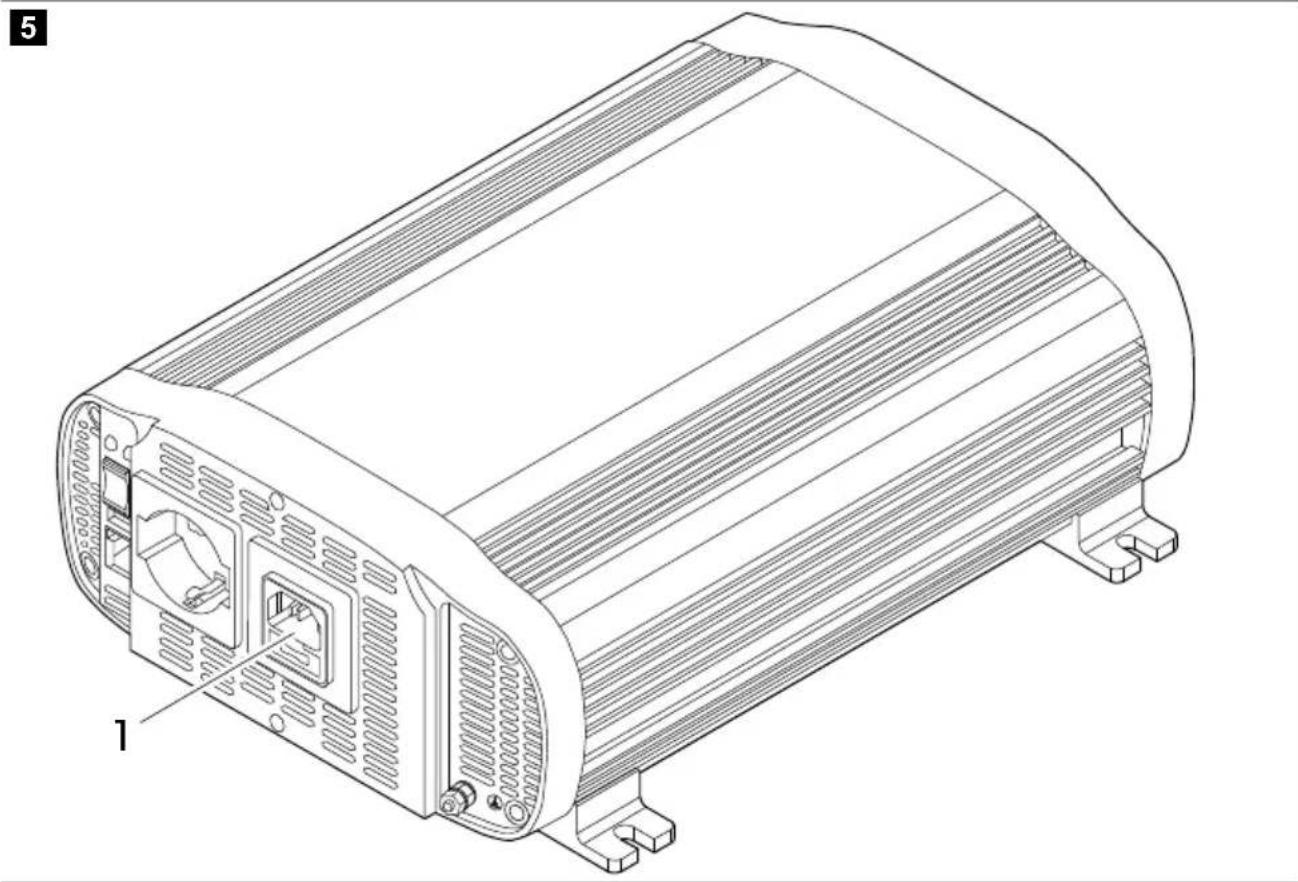
10 Connecting the external mains power supply (SP1000I-12, SP1500I-12 and SP2000I-12 models)
It is possible to connect an IEC cable into the external mains socket to feed the connected appliances directly with AC voltage from the public power network.
fig. 5 on page 4
Connect the cable to the socket①
11 Connecting the remote control
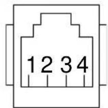
The device can be remotely controlled with an optional external switch (RC03) or any generic switch configured to the RJ11 connector of the device. The following description of pin configurations can be used as a guideline when using generic external switches.
fig. 6 on page 4
The optional RC03 external switch is using the following pin configuration:
EN
To enable the remote control, switch the On/Off switch to position 2.
12 Operation
fig. 7 on page 5
The On/Off switch
To turn the device on, press the On/Off switch to position 1.
To turn the device off, press the On/Off switch to position 0.
To enable the remote control, press the On/Off switch to position 2.
LED indicators
The device is equipped with a green ② and a red LED indicator, to display operating status.
| LED Description | |
| Green The device is on and properly operating | |
| Red Device malfunction | |
13 Fuse replacement

WARNING!
- Electrocution hazard
- The installation may only be carried out by a qualified electrician.
The device is protected by an integral electronic circuit. Also, fuses are located inside the device. In case of reversed polarity of a connection, a fuse blows. Devices with IVT function also feature a glass fuse inside the IEC socket for the external mains connection. Spare fuses are included in the product packaging.
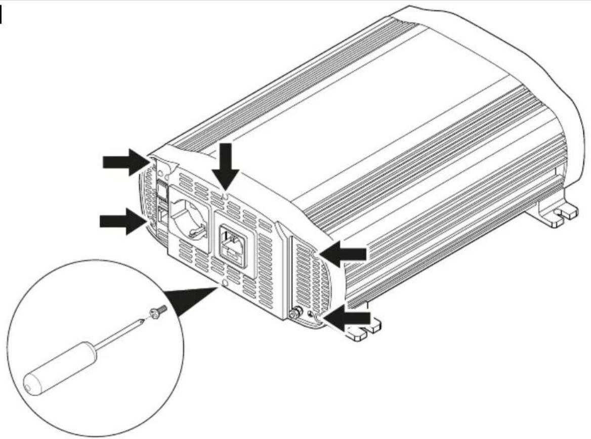
Replacing internal fuses
fig. 8 on page 5
- Remove the six screws.
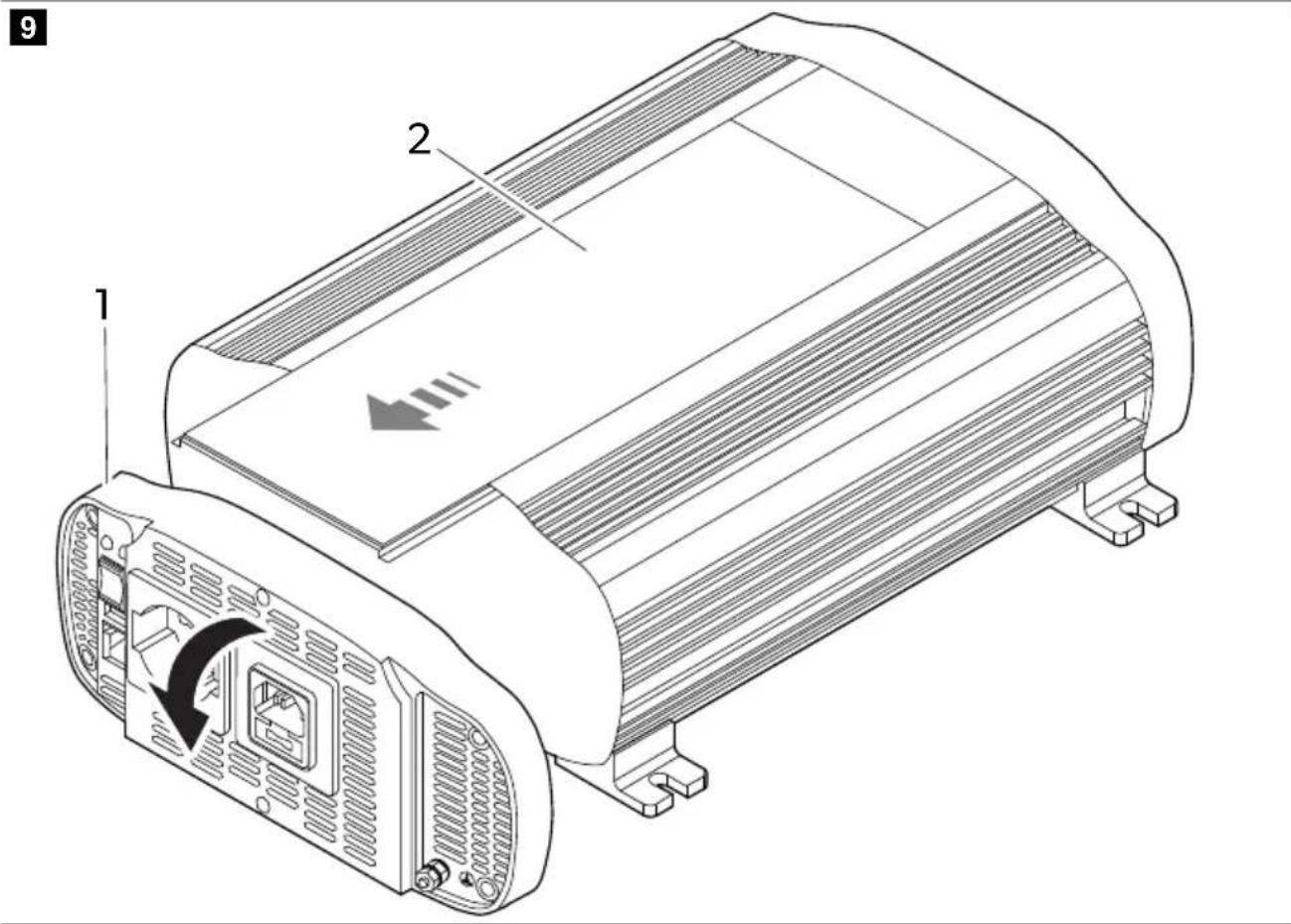
fig. 9 on page 6
-
Tilt the front panel forward. ①
-
Remove the lid. ②
EN
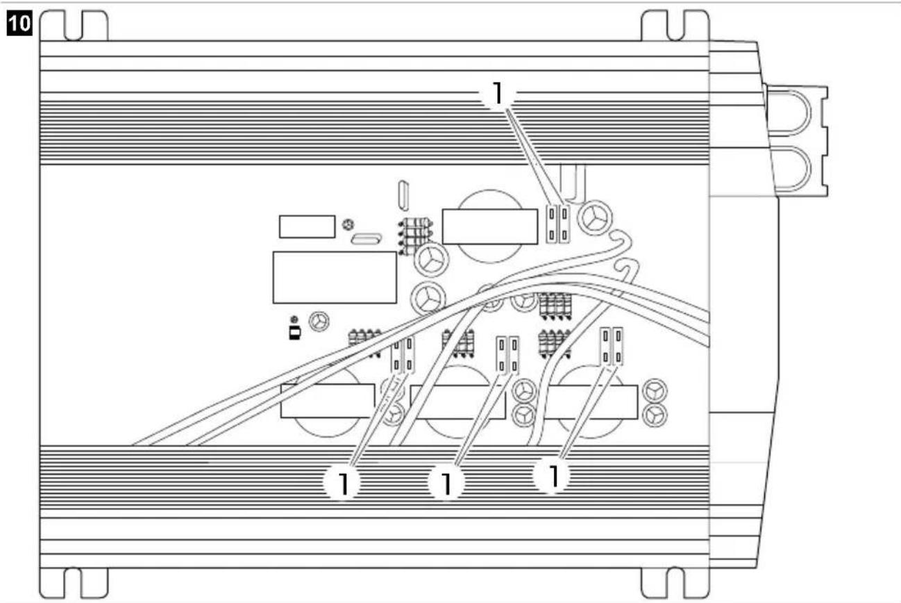
fig. 10 on page 6
- Replace the fuse . ①
| Model Fuse quantity Fuse rating | ||
| SM400-12, SP400-12 1 50 A (red) | ||
| SM600-12, SP600-12 2 50 A (red) | ||
| SM600-24, SP600-24 2 25 A (white) | ||
| SM1000-12, SP1000-12 4 30 A (green) | ||
| SM1500-12, SP1500-12 6 30 A (green) | ||
| SP1500-24 6 15 A (blue) | ||
| SP2000-12 8 30 A (green) | ||
| SP3000-12 | 12 | 30 A (green) |
| SP3000-24 | 12 | 15 A (blue) |
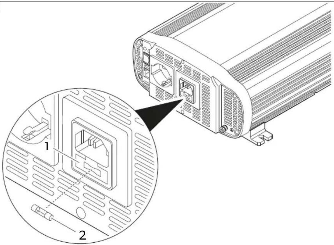
Replacing the IEC socket fuse
fig. 11 on page 7
- Open the lid of the socket housing.
- Replace the fuse . ②
| Model Fuse quantity Fuse rating | ||
| SP1000I-12, SP1500I-12 and SP2000I-12 | 1 | 10 A (F10AL 250V glass fuse) |

Note After fuse replacement, the device automatically restarts itself. If the device is not working properly after the fuse replacement, contact a technician to troubleshoot the problems.
14 Cleaning and maintenance
Occasionally clean the product with a damp cloth.
Check that the input and output connections are tight and secure.
Make sure that the ventilation slots are not obstructed by dirt or any material.
15 Disposal

Recycling packaging material: Place the packaging material in the appropriate recycling waste bins wherever possible.

Recycling products with non-replaceable batteries, rechargeable batteries or light sources:
- If the product contains any non-replaceable batteries, rechargeable batteries or light sources, you don't have to remove them before disposal.
- If you wish to finally dispose of the product, ask your local recycling center or specialist dealer for details about how to do this in accordance with the applicable disposal regulations.
• The product can be disposed free of charge.
16 Warranty
The statutory warranty period applies. If the product is defective, please contact the manufacturer's branch in your country (see dometic.com/dealer) or your retailer.
For repair and warranty processing, please include the following documents when you send in the device:
• A copy of the receipt with purchasing date
- A reason for the claim or description of the fault
Note that self-repair or nonprofessional repair can have safety consequences and might void the warranty.
17 Technical data
| SM400-12 SM600-12 SM600-24 | |||
| Continuous output power 400 W 600 W | |||
| Peak output power 800 W (few seconds) 1200 W (few seconds) | |||
| Output voltage (RMS)/Frequency | 230 VAC / 50 Hz ± 3 Hz | ||
| USB output 5 V 2.1 A | |||
| Input voltage 12 V 24 V | |||
| Self-consumption | 200 mA | 510 mA | 170 mA |
| Dimensions (W x D x H) | 140 mm × 184 mm × 71 mm | 140 mm × 214 mm × 71 mm | 140 mm × 214 mm × 72 mm |
| Certificate |  | ||
| SM1000-12 | SM1500-12 | |
| Continuous output power | 1000 W | 1500 W |
| Peak output power | 2000 W (few seconds) | 3000 W (few seconds) |
| Output voltage (RMS)/Frequency | 230 VAC / 50 Hz ± 3 Hz | |
| USB output 5 V 2.1 A | ||
| Input voltage | 12 V | |
| Self-consumption | 330 mA 560 mA | |
| Dimensions (W x D x H) | 262 mm × 270 mm × 121 mm | 262 mm × 270 mm × 107.5 mm |
EN
| SM1000-12 SM1500-12 | ||
| Certificate |  |  |
| SP400-12 SP600-12 SP600-24 | |||
| Continuous output power 400 W 600 W | |||
| Peak output power 1000 W (few seconds) 1500 W (few seconds) | |||
| Output voltage (RMS)/Frequency | 230 VAC / 50 Hz ± 3 Hz | ||
| USB output 5 V 2.1 A | |||
| Input voltage 12 V 24 V | |||
| Self-consumption | 325 mA | 375 mA | 210 mA |
| Dimensions (W x D x H) | 140 mm × 214.5 mm × 71 mm | 140 mm × 244.5 mm × 71 mm | 140 mm × 244.5 mm × 71 mm |
| Certificate |  |  | |
| SP1000-12 | SP1000I-12 | |
| Continuous output power | 1000 W | |
| Peak output power | 2500 W (few seconds) | |
| Output voltage (RMS)/Frequency | 230 VAC / 50 Hz ± 3 Hz | |
| USB output 5 V 2.1 A | ||
| Input voltage | 12 V | |
| Self-consumption | 490 mA | |
| Switching time from bat-tery to external mains | -0.02 s | |
| Switching time from ex-ternal mains to battery | -0.1 s | |
| Dimensions (W x D x H) | 262.4 mm × 270 mm × 107.5 mm | 262.4 mm × 270 mm × 121 mm |
| Certificate |   | |
| SP1500-12 | SP1500I-12 | SP1500-24 | |
| Continuous output power | 1500 W | ||
| Peak output power | 4000 W (few seconds) | ||
| Output voltage (RMS)/Frequency | 230 VAC / 50 Hz ± 3 Hz | ||
| USB output 5 V 2.1 A | |||
| Input voltage | 12 V | 24 V | |
| Self-consumption | 590 mA | 300 mA | |
EN
| SP1500-12 SP1500I-12 SP1500-24 | |||
| Switching time from battery to external mains | -0.02 s- | ||
| Switching time from external mains to battery | -0.1 s- | ||
| Dimensions (W x D x H) 270 mm ×322.4 mm × 107.5 mm | 270 mm ×322.4 mm × 121 mm | 270 mm ×322.4 mm × 107.5 mm | |
| Certificate |  |  |  |
| OS | , | ||
SP2000I-12 SP3000-12 SP3000-24
| Continuous output power 2000 W 3000 W | |||
| Peak output power | 6000 W (few seconds) | 8000 W (few seconds) | |
| Output voltage (RMS)/Frequency | 230 VAC / 50 Hz ± 3 Hz | ||
| USB output | 5 V 2.1 A | ||
| Input voltage | 12 V | 24 V | |
| Self-consumption | 690 mA | 1270 mA | 725 mA |
| Switching time from bat-tery to external mains | 0.02 s | - | - |
| Switching time from ex-ternal mains to battery | 0.1 s | - | - |
| Dimensions (W x D x H) 270 mm ×385 mm × 107.5 mm | 270 mm ×412 mm × 107.5 mm | 270 mm ×412 mm × 107.6 mm | |
| Certificate |  |  |  |
| OS | |||
German
7 Description technique
SP2000I-12 SP3000-12 SP3000-24
SP2000I-12 SP3000-12 SP3000-24
SP2000I-12 SP3000-12 SP3000-24
| Afmetingen (b x d x h) 270 mm ×385 mm × 107.5 mm | 270 mm ×412 mm × 107.5 mm | 270 mm ×412 mm × 107.6 mm | |
| Certificaat | UKCA CE(10-R-05-0094) | ||
Danish
SP2000I-12 SP3000-12 SP3000-24
SP2000I-12 SP3000-12 SP3000-24
SP2000I-12 SP3000-12 SP3000-24
SP2000I-12 SP3000-12 SP3000-24
SP2000I-12 SP3000-12 SP3000-24
SP2000I-12 SP3000-12 SP3000-24
SP2000I-12 SP3000-12 SP3000-24
SP2000I-12 SP3000-12 SP3000-24
SP2000I-12 SP3000-12 SP3000-24
SP2000I-12 SP3000-12 SP3000-24
SP2000I-12 SP3000-12 SP3000-24