SinePower DSP 412 - Inverter DOMETIC - Free user manual and instructions
Find the device manual for free SinePower DSP 412 DOMETIC in PDF.

| Product Type | Sine Wave Inverter |
| Brand | Dometic |
| Model | SinePower DSP 412 |
| Nominal Input Voltage | 12 V === |
| Input Voltage Range | 10 – 16.5 V === |
| Output Voltage | 230 V~ ± 10%, pure sine wave (THD < 5%) |
| Output Frequency | 50 Hz ± 0.5 Hz |
| Nominal Power | 350 W |
| Maximum Power (1 min) | 400 W |
| Peak Power (1 s) | 700 W |
| Maximum Efficiency | > 90% |
| USB Port | 5 V, 2000 mA |
| Weight | 1.2 kg |
| Operating Temperature | 0 °C to +50 °C |
| Storage Temperature | -30 °C to +70 °C |
| Allowable Humidity | 0 – 95%, non-condensing |
| Integrated Protections | Undervoltage, overvoltage, short circuit, overload, overtemperature |
| Cooling | Fan controlled by temperature and load |
| Mounting | Horizontal or vertical, minimum clearance 5 cm |
| Intended Use | Vehicle |
| Delivery Contents | Inverter, bracket, fixing screws, user manual |
| Warranty | Statutory, contact dealer or Dometic |
Frequently Asked Questions - SinePower DSP 412 DOMETIC
User questions about SinePower DSP 412 DOMETIC
0 question about this device. Answer the ones you know or ask your own.
Ask a new question about this device
Download the instructions for your Inverter in PDF format for free! Find your manual SinePower DSP 412 - DOMETIC and take your electronic device back in hand. On this page are published all the documents necessary for the use of your device. SinePower DSP 412 by DOMETIC.
USER MANUAL SinePower DSP 412 DOMETIC
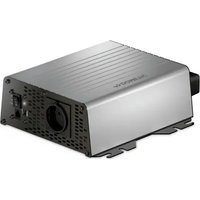
natural_image
Line drawing of a rectangular electronic device with a cable and connector (no text or symbols)
DSP 212, DSP 224, DSP 412, DSP 424
Sine wave inverter
Installation and Operating Manual.....8
© 2023 Dometic Group. The visual appearance of the contents of this manual is protected by copyright and design law. The underlying technical design and the products contained herein may be protected by design, patent or be patent pending. The trademarks mentioned in this manual belong to Dometic Sweden AB. All rights are reserved.
3
4
7
8
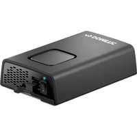
natural_image
Line drawing of a device with an attached cable and connector, showing no text or symbols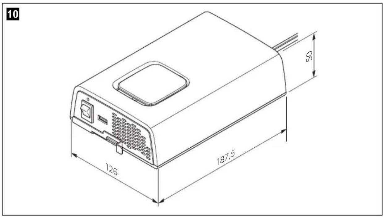
Please read these instructions carefully and follow all instructions, guidelines, and warnings included in this product manual in order to ensure that you install, use, and maintain the product properly at all times. These instructions MUST stay with this product.
By using the product, you hereby confirm that you have read all instructions, guidelines, and warnings carefully and that you understand and agree to abide by the terms and conditions as set forth herein. You agree to use this product only for the intended purpose and application and in accordance with the instructions, guidelines, and warnings as set forth in this product manual as well as in accordance with all applicable laws and regulations. A failure to read and follow the instructions and warnings set forth herein may result in an injury to yourself and others, damage to your product or damage to other property in the vicinity. This product manual, including the instructions, guidelines, and warnings, and related documentation, may be subject to changes and updates. For up-to-date product information, please visit documents.dometic.com.
Table of contents
1 Explanation of symbols....8
2 General safety instructions 9
3 Scope of delivery ....13
4 Intended use....13
5 Technical description....13
6 Fitting the inverter....15
7 Connecting the inverter....16
8 Using the inverter .....16
9 Cleaning and caring for the inverter....17
10 Troubleshooting....18
11 Warranty ....18
12 Disposal....19
13 Technical data....19
1 Explanation of symbols

DANGER!
Safety instruction: Indicates a hazardous situation that, if not avoided, will result in death or serious injury.

WARNING!
Safety instruction: Indicates a hazardous situation that, if not avoided, could result in death or serious injury.

NOTICE!
Indicates a situation that, if not avoided, can result in property damage.

NOTE
Supplementary information for operating the product.
2 General safety instructions
2.1 General safety
This product is only suitable for the intended purpose and application in accordance with these instructions.
This manual provides information that is necessary for proper installation and/or operation of the product. Poor installation and/or improper operating or maintenance will result in unsatisfactory performance and a possible failure.
The manufacturer accepts no liability for any injury or damage to the product resulting from:
- Incorrect assembly or connection, including excess voltage
- Incorrect maintenance or use of spare parts other than original spare parts provided by the manufacturer
• Alterations to the product without express permission from the manufacturer - Use for purposes other than those described in this manual
Dometic reserves the right to change product appearance and product specifications.
Note the following basic safety information when using electrical devices to protect against:
- Electric shock
- Fire hazards
- Injury
2.2 General safety

DANGER!
- In the event of fire, use a fire extinguisher which is suitable for electrical devices.

WARNING!
- Only use the device as intended.
- Ensure that the red and black terminals never come into contact.
- Disconnect the device from the mains:
– Before cleaning and maintenance
- Before changing a fuse
- If you disassemble the device:
- Detach all connections
-
Make sure that no voltage is present at any of the inputs and outputs
-
The device may not be used if the device itself or the connection cable are visibly damaged.
- If this power cable for this device is damaged, it must be replaced by the manufacturer, customer service or a similarly qualified person in order to prevent safety hazards.
- This device may only be repaired by qualified personnel. Inadequate repairs may cause serious hazards.
- This device can be used by children aged 8 years or over, as well as by persons with diminished physical, sensory or mental capacities or a lack of experience and/or knowledge, providing they are supervised or have been taught how to use the device safely and are aware of the resulting risks.
• Electrical devices are not toys.
Always keep and use the appliance out of the reach of children.
- Children must be supervised to ensure that they do not play with the device.

NOTICE!
- Before start-up, check that the voltage specification on the type plate is the same as that of the power supply.
- Ensure that other objects cannot cause a short circuit at the contacts of the device.
- Never pull the plug out of the socket by the connection cable.
- Store the device in a dry and cool place.
2.3 Safety when installing the device

DANGER!
- Never mount the device anywhere where there is a risk of gas or dust explosion.

CAUTION!
- Ensure that the device is standing firmly. The device must be set up and fastened in such a way that it cannot tip over or fall down.

NOTICE!
- Do not expose the device to a heat source (such as direct sunlight or heating). Avoid additional heating of the device in this way.
- Set up the device in a dry location where it is protected against splashing water.
2.4 Safety when connecting the device electronically

DANGER! Danger of electrocution
- If you are working on electrical systems, ensure that there is somebody close at hand who can help you in emergencies.

WARNING!
- Never connect more than one consumer device to the inverter. If you connect more than one device, a short circuit may occur.
- Make sure that the lead has a sufficient cross-section.
- Lay the cables so that they cannot be damaged by the doors or the bonnet.
Crushed cables can lead to serious injury.

CAUTION!
- Lay the cables so that they cannot be tripped over or damaged.

NOTICE!
- Use ductwork or cable ducts if it is necessary to lay cables through metal panels or other panels with sharp edges.
- Do not lay the 230 V mains cable and the 12 V DC cable in the same duct.
- Do not lay the cable so that it is loose or heavily kinked.
- Fasten the cables securely.
- Do not pull on the cables.
2.5 Operating the device safely

DANGER! Danger of electrocution
- Do not touch exposed cables with your bare hands. This applies especially when operating the device from the AC mains.

WARNING!
- Only use the device in closed, well-ventilated rooms.

CAUTION!
• D o not operate the device
– In salty, wet or damp environments
– In the vicinity of corrosive fumes
– In the vicinity of combustible materials
– In areas where there is a danger of explosions.
- Before starting the device, ensure that the power supply line and the plug are dry.
• Always disconnect the power supply when working on the device. - Please observe that parts of the device may still conduct voltage even if the fuse has blown.
- Do not disconnect any cables when the device is still in use.

NOTICE!
- Make sure the air inlets and outlets of the device are not covered.
- Ensure good ventilation.
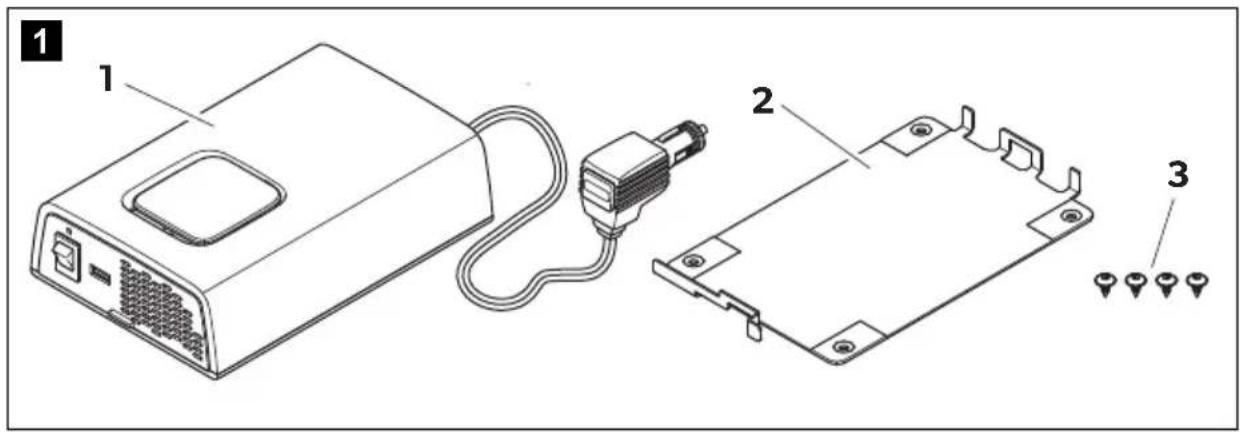
3 S c o p e o f d
No. in
fig. 1,
page 3
Designation
1 Sine wave inverter
2 Holder
3 Fixing screws
- Operating manual
4 Intended use

WARNING!
Never use the inverter on vehicles where the positive terminal of the battery is connected to the chassis.
The wave inverter converts direct current into a 230 V AC supply of 50 Hz:
Rechargeable devices with USB interface can be charged via the USB port (5 V, 2000 mA).
This device is exclusively intended for vehicle use.
5 Technical description
The inverters can be operated wherever a DC connection is available:
The output voltage corresponds to the household voltage from the socket (pure sine wave, THD < 5%).
Please observe the values for constant output power and peak output power as indicated in chapter "Recycling packaging material" on page 19. Never connect devices that have a higher power requirement.

NOTE
Note when connecting devices with an electrical drive (such as power drills and refrigerators), that they often require more power than is indicated on the type plate.
The inverter has various protective mechanisms.
• Overvoltage shutdown: The inverter shuts itself off when the voltage exceeds the cut-off value. It restarts when the voltage returns to the restart value.
- Undervoltage shutdown: The inverter shuts itself off when the voltage sinks below the cut-off value. It restarts when the voltage rises to the restart value.
- Excess temperature shutdown: The inverter switches off when the temperature inside the device or the temperature on the cooling element exceeds a cut-off value. It restarts when the voltage rises to the restart value.
• Overloading and short circuit shutdown: The LED on the inverter indicates an operating fault when an excess load is connected or a short circuit has occurred.

NOTE
The individual values are found in the chapter "Recycling packaging material" on page 19.
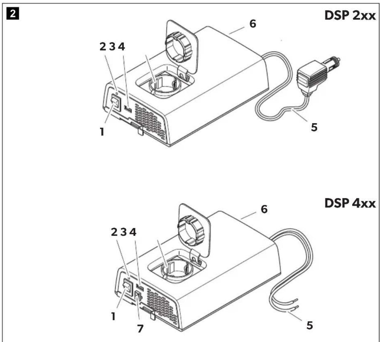
5.1 Control elements
No. in fig. 2, Description page 3
1 Main switch: Switches the device on and off
2 Status LED: See chapter "Status indications" on page 17
5.2 Connections

NOTE
The version for continental Europe is depicted.
| No. in fig. 2, Description page 3 |
| 3 USB connection |
| 4 AC outlet |
| 5 DC plug |
| 6 Fan (backside) |
| 7 DSP412, DSP424 only: Connection for external switch |
6 Fitting the inverter
6.1 Mounting instructions
When selecting the installation location, observe the following instructions:
- The inverter can be mounted horizontally or vertically.
- The inverter must be installed in a place that is protected from moisture.
- The inverter may not be installed in the presence of flammable materials.
- The inverter may not be installed in a dusty environment.
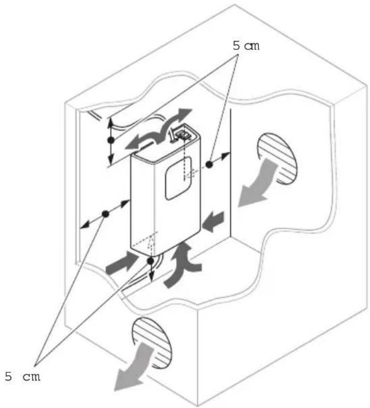
- The place of installation must be well ventilated. A ventilation system must be available for installations in small, enclosed spaces. The minimum clearance around the inverter must be at least 5 cm (fig. 3, page 4).
- The air intake on the underside or the air outlet on the back of the inverter must remain clear.
- For ambient temperatures higher than 40 °C (such as in engine or heating compartments, or direct sunlight), the inverter's maximal output load is reduced. Thereby the inverter may shut down due to overload.
- The device must be installed on a level and sufficiently sturdy surface.

NOTICE!
Before drilling any holes, make sure that no electrical cables or other parts of the vehicle can be damaged by drilling, sawing and filing.
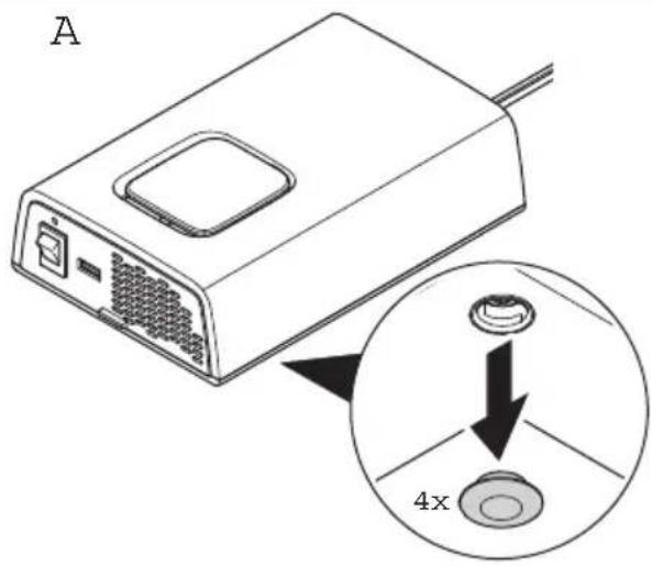
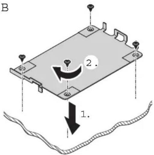
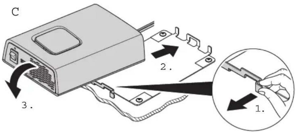
6.2 Mounting the inverter
▶ Mount the inverter as shown (fig. 4, page 4).
7 Connecting the inverter

WARNING!
Never connect more than one consumer device to the inverter. The connection of more than one device must be executed by an electrically qualified person complying with the local requirements for protection against electric shock.

NOTICE!
- Incorrect polarity will blow an internal fuse which has to be replaced by the Dometic service. Additionally the electronics may be damaged.
- Make sure that the inverter is operated with the following voltage only:
-DSP212, DSP412: 12 V= - DSP224, DSP424: 24 V=
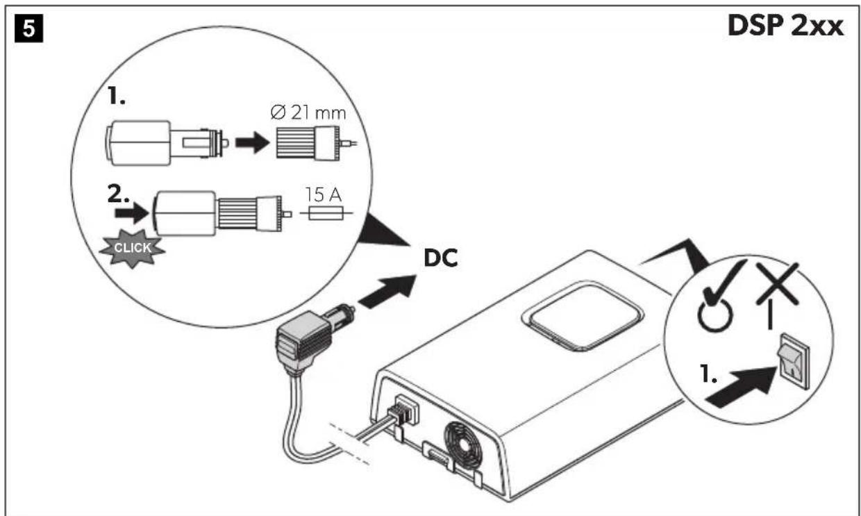
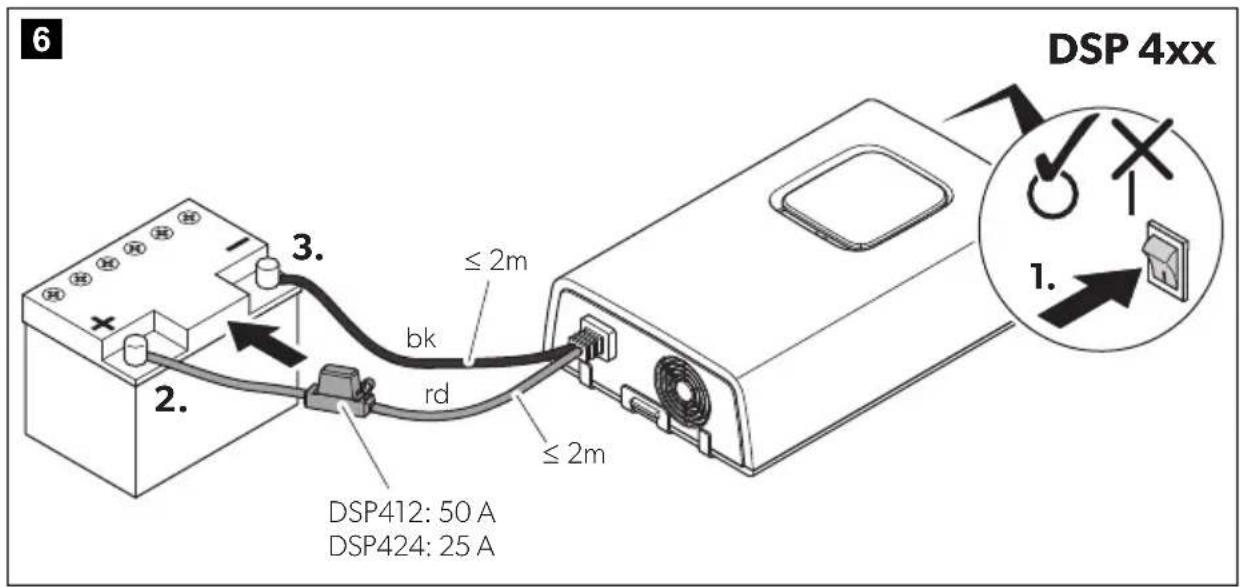
▶ Connect the inverter as shown:
- Connecting the battery:
DSP212, DSP224: fig. 5, page 5
DSP412, DSP424: fig. 6, page 5
- Connecting load: fig. 7, page 6
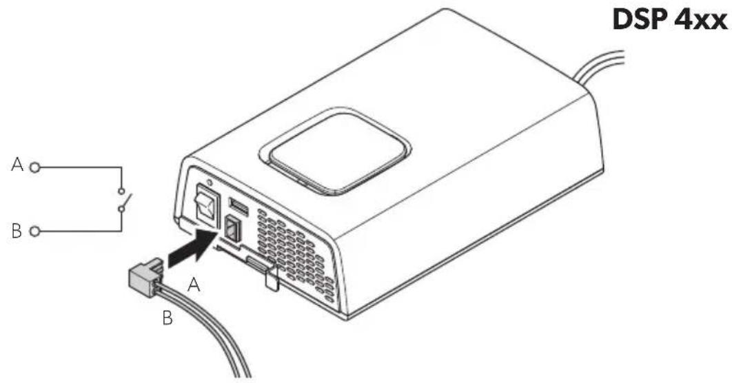
Connect external switch to turn device on and off (DSP412, DSP424 only)

NOTE
The inverter is switched on when the external or the main switch (fig. 2 1, page 3) is switch on. If the inverter shall be controlled via external switch only, the main switch has to be switch to position "0".
▶ Connect the external switch as shown (fig. 8, page 6).
8 Using the inverter

CAUTION!
When connecting the load observe the applicable regulations.
8.1 Switching on the inverter
▶ Switch the inverter on by pressing the switch (fig. 2 1, page 3) on the device (position "I") ...
▶ ... or (DSP412, DSP424 only) switch on the inverter using the external switch (optional).
√ The blue Status LED lights up (fig. 2 2, page 3).
√ The power consuming device is supplied with voltage.
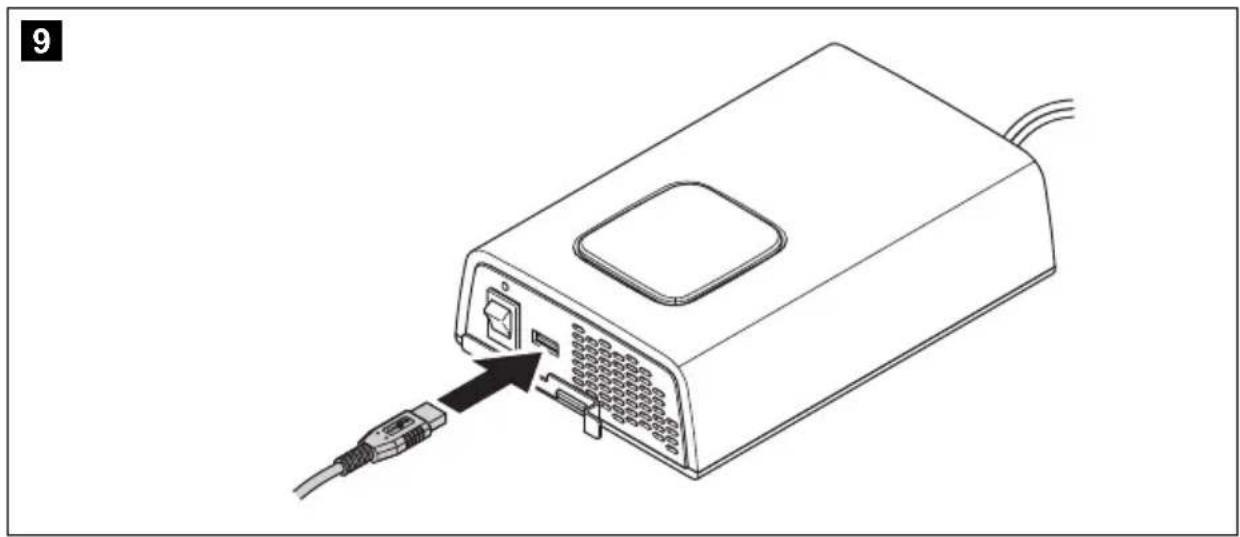
Charging the device via the USB port

NOTE
Also observe the operating manual of the device you want to charge via the USB port.
▶ Connect the device to the USB port as shown (fig. 9, page 7).
8.2 Status indications
The blue LED (fig. 2 2, page 3) shows the operating condition of the inverter.
Display Input voltage
Constantly lit Normal mode
Long flash, short interruption Inverter overheated/Overload
| Quick flash | Overvoltage/Undervoltage |
| Off | Other fault |
9 Cleaning and caring for the inverter

NOTICE! Damage hazard
- Never clean the cooling device under running water or in dish water.
- Do not use abrasive cleaning agents or hard objects during cleaning as these can damage the cooling device.
▶ Occasionally clean the cooling device interior and exterior with a damp cloth.
▶ Make sure that the air inlet and outlet vents on the device are free of any dust and dirt, so that heat can be released and the device is not damaged.
10 Troubleshooting

WARNING!
Do not open the device. You risk sustaining an electric shock by doing this.

NOTE
If you have detailed questions on the specifications of the inverter please contact the manufacturer (addresses on the back of the instruction manual).
The LED (fig. 2 2, page 3) indicates the fault:
LED display Cause Remedy
| Quick flash Input voltage is too high Check the input voltage and reduce it. | |
| Input voltage too low The battery needs recharging.Check the cables and connections. | |
| Long flash, short interruption | Overheating Switch off the inverter and the consumer.Wait 5 to 10 minutes and switch the inverter on again without any electric consumers.Reduce the load and make sure the inverter has better ventilation. Then switch the con-sumer back on. |
| Excessive load Switch off the inverter and remove the consumer.Then switch the inverter back on without the consumer. If no excessive load is now shown, then there is a short circuit in the consumer or the total load was higher than the power specified on the data sheet.Check the cables and connections. | |
| Off Other fault | Contact the service. |
11 Warranty
The statutory warranty period applies. If the product is defective, please contact your retailer or the manufacturer's branch in your country (see dometic.com/dealer).
For repair and warranty processing, please include the following documents when you send in the product:
• A copy of the receipt with purchasing date
- A reason for the claim or description of the fault
Note that self-repair or non-professional repair can have safety consequences and might void the warranty.
12 Disposal
Recycling products with non-replaceable batteries, rechargeable batteries or light sources
If the product contains any non-replaceable batteries, rechargeable batteries or light sources, you don't have to remove them before disposal.
If you wish to finally dispose of the product, ask your local recycling center or specialist dealer for details about how to do this in accordance with the applicable disposal regulations.
The product can be disposed free of charge.
Recycling packaging material

Place the packaging material in the appropriate recycling waste bins wherever possible.
13 Technical data
The following technical data applies to all inverters:
| Output voltage: | 230 V~ ± 10 %, pure sine wave (THD < 5%) |
| Output frequency: 50 Hz ± 0,5 Hz | |
| Maximum efficiency: >90 % | |
| Heat dissipation: temperature and load controlled fan | |
| Ambient temperature at operation: 0 °C to +50 °C | |
| Ambient temperature for storage: -30 °C to +70 °C | |
| Air humidity: 0 – 95%, non-condensing | |
| Testing/certification: | CE E9 |
| DSP212 D | SP412 DSP2 | 24 DSP424 | ||
| Ref. no.: 9600002603 | 9600003593 | 96000025419600003595 | 96000025409600003594 | 96000025429600003596 |
| Rated input voltage: | 12 V--- | 24 V--- | ||
| Input voltage range: | 10 – 16.5 V--- | 20 – 33 V--- | ||
| Rated load: | 150 W | 350 W | 150 W | 350 W |
| Maximum power for 1 min: | 170 W | 400 W | 170 W | 400 W |
| Surge power for 1 s: | 300 W | 700 W | 300 W | 700 W |
| Idle current consumption: | <0,6 A | <0,4 A | <0,6 A | <0,4 A |
| Dimensions W x L x H: | fig. 10, page 7 | |||
| Weight: | 1.1 kg | 1.2 kg | 1.1 kg | 1.2 kg |
Protective devices
| 12 V 24 V | ||
| Input: Undervoltage | ||
| AC output: Overvoltage, short circuit, overload | ||
| Temperature: Shutdown | ||
| Short circuit protection: Yes, Ipk | ||
Overvoltage shutdown
| Device | Overvoltage | |
| Shutdown Restart | ||
| DSP212, DSP412 16.5 V 15.5 V | ||
| DSP224, DSP424 33 V 31 V | ||
Undervoltage shutdown
| Device | Undervoltage | |
| Shutdown Restart | ||
| DSP212, DSP412 10 V 12 V | ||
| DSP224, DSP424 20 V 24 V | ||
For the current EU declaration of conformity for your device please refer to the respective product page on dometic.com or contact the manufacturer directly (see back page).
5 Description technique 42
5 Description technique
DSP412, DSP424: obr. 6, strane 5
dometic.com/sales-offices