SinePower DSP 612 - Inverter DOMETIC - Free user manual and instructions
Find the device manual for free SinePower DSP 612 DOMETIC in PDF.

| Product type | Sine wave inverter |
| Brand | Dometic |
| Model | SinePower DSP 612 |
| Nominal input voltage | 12 V DC (range 10 - 16.5 V) |
| Output voltage | 230 V AC ± 10%, sine wave (distortion < 5%) |
| Output frequency | 50 Hz ± 0.5 Hz |
| Rated power | 600 W |
| Peak power (1 s) | 1200 W |
| Efficiency | > 90% |
| No-load consumption (12 V) | < 0.8 A |
| Standby consumption | < 0.3 A |
| Integrated protections | Overvoltage, undervoltage, overload, short circuit, overtemperature |
| Cooling | Temperature and load controlled fan |
| Operating temperature | 0 °C to +50 °C |
| Weight | 2.8 kg |
| Dimensions (L x D x H) | See fig. 15 in the manual |
| Main functions | DC/AC converter, remote control, energy saving mode, TN/IT grid selection |
| Maintenance and cleaning | Clean with a damp cloth; do not use detergents or hard objects |
| Safety | Do not open the device; risk of electric shock; only use qualified professionals for connection |
| Delivery contents | Inverter, remote control, remote control cable, user manual |
| Warranty | Legal warranty; contact reseller or manufacturer |
Frequently Asked Questions - SinePower DSP 612 DOMETIC
User questions about SinePower DSP 612 DOMETIC
0 question about this device. Answer the ones you know or ask your own.
Ask a new question about this device
Download the instructions for your Inverter in PDF format for free! Find your manual SinePower DSP 612 - DOMETIC and take your electronic device back in hand. On this page are published all the documents necessary for the use of your device. SinePower DSP 612 by DOMETIC.
USER MANUAL SinePower DSP 612 DOMETIC
natural_image
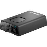
Exterior view of a silver electronic device with ventilation grilles and ports (no visible text or symbols)DSP612, DSP624, DSP1012, DSP1024, DSP1512, DSP1524, DSP2012, DSP2024
Sine wave inverter
Installation and Operating Manual.....3
© 2023 Dometic Group. The visual appearance of the contents of this manual is protected by copyright and design law. The underlying technical design and the products contained herein may be protected by design, patent or be patent pending. The trademarks mentioned in this manual belong to Dometic Sweden AB. All rights are reserved.
Please read these instructions carefully and follow all instructions, guidelines, and warnings included in this product manual in order to ensure that you install, use, and maintain the product properly at all times. These instructions MUST stay with this product.
By using the product, you hereby confirm that you have read all instructions, guidelines, and warnings carefully and that you understand and agree to abide by the terms and conditions as set forth herein. You agree to use this product only for the intended purpose and application and in accordance with the instructions, guidelines, and warnings as set forth in this product manual as well as in accordance with all applicable laws and regulations. A failure to read and follow the instructions and warnings set forth herein may result in an injury to yourself and others, damage to your product or damage to other property in the vicinity. This product manual, including the instructions, guidelines, and warnings, and related documentation, may be subject to changes and updates. For up-to-date product information, please visit documents.dometic.com.
Contents
1 Explanation of symbols....3
2 General safety instructions ....4
3 Scope of delivery ....7
4 Target group for this manual....7
5 Intended use....8
6 Technical description ....8
7 Fitting the inverter .... 11
8 Connecting the inverter....12
9 Using the inverter .....14
10 Cleaning and caring for the inverter....16
11 Troubleshooting....17
12 Warranty ....18
13 Disposal....18
14 Technical data....18
1 Explanation of symbols
DANGER!
Safety instruction: Indicates a hazardous situation that, if not avoided, will result in death or serious injury.

WARNING!
Safety instruction: Indicates a hazardous situation that, if not avoided, could result in death or serious injury.

CAUTION!
Safety instruction: Indicates a hazardous situation that, if not avoided, could result in minor or moderate injury.

NOTICE!
Indicates a situation that, if not avoided, can result in property damage.

NOTE
Supplementary information for operating the product.
2 General safety instructions
2.1 General safety
Note the following basic safety information when using electrical devices to protect against:
- Electric shock
- Fire hazards
- Injury
2.2 General safety

DANGER!
- In the event of fire, use a fire extinguisher which is suitable for electrical devices.

WARNING!
- Only use the device as intended.
- Ensure that the red and black terminals never come into contact.
- Disconnect the device from the power supply:
– Before cleaning and maintenance
– Before changing a fuse
- If you disassemble the device:
- Detach all connections
- Make sure that no voltage is present at any of the inputs and outputs
- The device may not be used if the device itself or the connection cable are visibly damaged.
- If this power cable for this device is damaged, it must be replaced by the manufacturer, customer service or a similarly qualified person in order to prevent safety hazards.
- This device may only be repaired by qualified personnel. Inadequate repairs may cause serious hazards.
- This device can be used by children aged 8 years or over, as well as by persons with diminished physical, sensory or mental capacities or a lack of experience and/or knowledge, providing they are supervised or have been taught how to use the device safely and are aware of the resulting risks.
• Electrical devices are not toys.
Always keep and use the appliance out of the reach of children.
- Children must be supervised to ensure that they do not play with the device.

NOTICE!
- Before start-up, check that the voltage specification on the type plate is the same as that of the power supply.
- Ensure that other objects cannot cause a short circuit at the contacts of the device.
- Never pull the plug out of the socket by the connection cable.
- Store the device in a dry and cool place.
2.3 Safety when installing the device
DANGER!
- Never mount the device anywhere where there is a risk of gas or dust explosion.

CAUTION!
- Ensure that the device is standing firmly. The device must be set up and fastened in such a way that it cannot tip over or fall down.

NOTICE!
- Do not expose the device to a heat source (such as direct sunlight or heating). Avoid additional heating of the device in this way.
- Set up the device in a dry location where it is protected against splashing water.
2.4 Safety when connecting the device electronically
DANGER! Danger of electrocution
- If you are working on electrical systems, ensure that there is somebody close at hand who can help you in emergencies.

WARNING!
- Make sure that the lead has a sufficient cross-section.
- Lay the cables so that they cannot be damaged by the doors or the bonnet.
Crushed cables can lead to serious injury.

CAUTION!
- Lay the cables so that they cannot be tripped over or damaged.

NOTICE!
- Use ductwork or cable ducts if it is necessary to lay cables through metal panels or other panels with sharp edges.
- Do not lay the 230 V mains cable and the 12 V DC cable in the same duct.
- Do not lay the cable so that it is loose or heavily kinked.
- Fasten the cables securely.
- Do not pull on the cables.
2.5 Operating the device safely
DANGER! Danger of electrocution
- Do not touch exposed cables with your bare hands.

WARNING!
- Only use the device in closed, well-ventilated rooms.

CAUTION!
• D o not operate the device
– In salty, wet or damp environments
– In the vicinity of corrosive fumes
– In the vicinity of combustible materials
– In areas where there is a danger of explosions.
- Before starting the device, ensure that the power supply line and the plug are dry.
• Always disconnect the power supply when working on the device. - Please observe that parts of the device may still conduct voltage even if the fuse has blown.
- Do not disconnect any cables when the device is still in use.

NOTICE!
- Make sure the air inlets and outlets of the device are not covered.
- Ensure good ventilation.
3 S c o p e o f d
No. in
fig. 1
Designation
1 Sine wave inverter
2 Remote control
3 Connection cable remote control
- Operating manual
4 Target group for this manual
The electrical installation (chapter "Connecting the inverter" on page 12) is intended for professionals who are familiar with the applicable regulations of the country in which the equipment is to be installed and/or used.
All other chapters are intended for the users.
5 Intended use

WARNING!
Never use the inverter on vehicles where the positive terminal of the battery is connected to the chassis.
The wave inverter converts direct current into a 230 V AC supply of 50 Hz:
• 12 V---: DSP612, DSP1012, DSP1512, DSP2012
• 24 V==: DSP624, DSP1024, DSP1524, DSP2024
This product is only suitable for the intended purpose and application in accordance with these instructions.
This manual provides information that is necessary for proper installation and/or operation of the product. Poor installation and/or improper operating or maintenance will result in unsatisfactory performance and a possible failure.
The manufacturer accepts no liability for any injury or damage to the product resulting from:
- Incorrect assembly or connection, including excess voltage
- Incorrect maintenance or use of spare parts other than original spare parts provided by the manufacturer
• Alterations to the product without express permission from the manufacturer - Use for purposes other than those described in this manual
Dometic reserves the right to change product appearance and product specifications.
6 Technical description
The inverters can be operated wherever a DC connection is available:
• 12 V---: DSP612, DSP1012, DSP1512, DSP2012
• 24 V---: DSP624, DSP1024, DSP1524, DSP2024
The light-weight and compact construction of this device allows for easy installation in mobile homes, commercial vehicles or motor and sailing yachts.
The output voltage corresponds to the household voltage from the socket (pure sine wave, THD <5%).
Please observe the values for constant output power and peak output power as indicated in chapter "Technical data" on page 18. Never connect devices that have a higher power requirement.

NOTE
Note when connecting devices with an electrical drive (such as power drills and refrigerators), that they often require more power than is indicated on the type plate.
The inverter has various protective mechanisms:
- Overvoltage shutdown: The inverter shuts itself off when the voltage exceeds the cut-off value. It restarts when the voltage returns to the restart value.
- Undervoltage shutdown: The inverter shuts itself off when the voltage sinks below the cut-off value. It restarts when the voltage rises to the restart value.
- Excess temperature shutdown: The inverter switches off when the temperature inside the device or the temperature on the cooling element exceeds a cut-off value. It restarts when the voltage rises to the restart value.
- Overloading and short circuit shutdown: The LED on the inverter indicates an operating fault when an excess load is connected or a short circuit has occurred.

NOTE
The individual values are found in the chapter “Technical data” on page 18.
The inverter can be operated in the following net configurations:
• TN network:
The neutral conductor of the inverter is grounded. A downstream safety switch (RCD) must be installed.
- IT network:
Both phases are insulated. This is suitable for operating one load. If more than one load will be connected a protection plan has to be set up (e.g. insulation monitor).
The net configuration is set via a DIP switch at the inverter.
The inverter can be switched with the remote control to an energy-saving mode to prevent the connected battery from discharging too quickly.
Using the remote control, the inverter can be turned on or off and switched to the energy-saving mode.
6.1 Control elements
No. in
fig. 2
Description Description
1 Main switch Switches the device on or off
2 Status LED See chapter "Status indications" on page 14
3 Dip switch Sets the net configuration
6.2 Connections

NOTE
The version for continental Europe is depicted.
No. in
fig. 2
Description
4 AC outlet
5 Remote control connection
6 DC connection
7 Ground terminal (Earthing on the vehicle bodywork)
8 Fan
6.3 Remote control
No. in
fig. 3
Description
1 On/off button
2 Status LED
3 Terminal for remote control
7 Fitting the inverter
7.1 Tools required
For the electrical connection you will need the following tools:
- Crimping tool
- 3multi-coloured, flexible connection cables. Determine the necessary thickness from the table in chapter "Connecting the inverter" on page 12.
- Cable lugs and conductor sleeves
For fastening you will require the following tools:
• Machine bolts (M4) with washers and self-locking nuts or
- self-tapping screws or wood screws
7.2 Mounting instructions
When selecting the installation location, observe the following instructions:
- The inverter can be mounted horizontally or vertically.
- The inverter must be installed in a place that is protected from moisture.
- The inverter may not be installed in the presence of flammable materials.
- The inverter may not be installed in a dusty environment.
- The place of installation must be well ventilated. A ventilation system must be available for installations in small, enclosed spaces. The minimum clearance around the inverter must be at least 5 cm (fig. 4).
- The air intake on the back or the air outlet on the front of the inverter must remain clear.
- For ambient temperatures higher than 40 °C (such as in engine or heating compartments, or direct sunlight), the inverter may shut down although the connected load is below the rated load (derating).
- The device must be installed on a level and sufficiently sturdy surface.

NOTICE!
Before drilling any holes, make sure that no electrical cables or other parts of the vehicle can be damaged by drilling, sawing and filing.
7.3 Mounting the inverter
▶ Mount the inverter as shown (fig. 5).
7.4 Mounting the remote control
-
Mount the remote control as shown (fig. 6).
-
Remove the protective film.
8 Connecting the inverter
8.1 General instructions

WARNING!
- The inverter may only be connected by a qualified workshop. The following information is intended for technicians who are familiar with the guidelines and safety precautions to be applied.
- Never use the inverter on vehicles where the positive terminal of the battery is connected to the chassis.
-
If you do not fit a fuse to the positive cable, the cables can overload, which might result in a fire.
-
When installed in vehicles or boats, the inverter must be connected to the chassis or earth.
- When setting up a socket distribution circuit (mains setup), comply with the applicable regulations.
- Only use copper cables.
- Keep the DC cables as short as possible (< 1 m).
- Keep to the specified cable cross section and fit a cable fuse (fig. 7 1) as close to the battery as possible on the positive cable (see the table).
| Device | Required cable cross section | Cable fuse |
| DSP612 25 mm ^2 150 A | ||
| DSP624 | 25 mm ^2 150 A | |
| DSP1012 | 35 mm ^2 | 200 A |
| DSP1024 | 25 mm ^2 150 A | |
| DSP1512 50 mm ^2 250 A | ||
| DSP1524 25 mm ^2 150 A | ||
| DSP2012 70 mm ^2 300 A | ||
| DSP2024 35 mm ^2 200 A |
8.2 Connecting the inverter

NOTICE!
- Make sure that you do not reverse the polarity. Incorrect polarity can damage the inverter.
- Make sure that the inverter is operated with the following voltage only:
-DSP612, DSP1012, DSP1512, DSP2012: 12 V=
-DSP624, DSP1024, DSP1524, DSP2024: 24 V=

NOTE
Tighten the nuts and bolts to a maximum torque of 15 Nm. Loose connections may cause overheating.
▶ Connect the inverter as shown:
- Connecting the battery: fig. 7
- Connecting the ground terminal fig. 8
- Connecting the 230 V output cable: fig. 9
8.3 Connecting the remote control

NOTICE!
Only plug in the connection to the remote control in the remote port. The device can be damaged by connecting it incorrectly.
▶ Connect the remote control as shown(fig. 10).
8.4 Connecting external switch (accessories)

NOTE
When using an external switch, you cannot change the status of energy saving mode.
▶ Close an external switch as shown (fig. 11).
9 Using the inverter
9.1 Switching on the inverter
▶ Set the main switch (fig. 2 1) of the inverter as follows.
- "0": Inverter completely switched off
- "I": Standard operation
- "II": Operation via remote control
√ The inverter performs a self-test.
√ After the self-test is completed successfully, the status LED (fig. 2 2) indicates the operation mode:
- Constantly lit: Normal mode activated
- Flashes four times: Energy-saving mode activated
9.2 Status indications
The LED (fig. 2 2) shows the operating condition of the inverter.
| Display Input voltage | |
| Constantly lit | Normal mode |
| Long flash, short interruption | Inverter overheated/Overload |
| Quick flash | Overvoltage/Undervoltage |
| Off | Other fault |
The inverter switches off if:
- The battery voltage drops below 10 V (12 V--- connection) or 20 V (24 V--- connection).
-
The battery voltage exceeds 16 V (12 V--- connection) or 32 V (24 V--- connection).
-
The inverter is overloaded.
- The inverter overheats.
In case of shutdown due to overvoltage or undervoltage the inverter restarts when the set voltage value is reached.
In case of shutdown due to overload or overheating proceed as follows:
- Shut down the inverter with the main switch (fig. 21).
- Check that the inverter is sufficiently ventilated and that the ventilation grilles are unimpeded.
- Wait 5 – 10 minutes and switch the inverter on again without any electric consumers.
9.3 Switching to energy-saving mode

NOTE
- The inverter automatically switches to normal operation when a load over 45 W is connected.
- If an external switch is connected, you cannot change the energy saving mode.
Activating energy saving mode
- If necessary, switch the inverter off.
- Press the on/off button (fig. 3 1) of the remote control until the status LED (fig. 3 2) of the remote control has flashed six times.
√ Then the status LED (fig. 3 2) of the remote control flashes every 5 seconds.
√ Energy saving mode is activated.
Deactivating energy saving mode
- Switch the inverter off.
- Press the on/off button (fig. 3 1) of the remote control until the status LED (fig. 3 2) of the remote control goes on constantly.
Before the status LED goes on constantly, it indicates that energy saving mode will be switched off by an interval of flashing four times followed by flashing six times.
√ Normal mode is activated.
9.4 Configuring the net configuration
DANGER!
Changing the net configuration results in risk of lethal injury.
The dip switch must only be set by qualified personnel.
Remove the the dip switch's protection cap for configuring only. Insert the protection cap to prevent switching the dip switch's setting.
Using the dip switch you can define in which net configuration the inverter shall operate.
| Parameter Dip switch | |
| TN grid | On |
| An external downstream circuit breaker (RCD) is necessary. | |
| IT grid | Off |
| Operation with one load only or installation of an external insulation monitor. | |
| National standards shall apply! | |
10 Cleaning and caring for the inverter

NOTICE! Damage hazard
Do not use sharp or hard objects or cleaning agents for cleaning as these may damage the product.
▶ Occasionally clean the product with a damp cloth.
11 Troubleshooting

WARNING!
Do not open the device. You risk sustaining an electric shock by doing this.

NOTE
If you have detailed questions on the specifications of the inverter please contact the manufacturer (addresses on the back of the instruction manual).
The LED (fig. 2 2) indicates the fault:
LED display Cause Remedy
| Quick flash Input voltage is too high | Check the input voltage and reduce it. |
| Input voltage too low | The battery needs recharging.Check the cables and connections. |
| 2 s lit, short interruption | Overheating Switch off the inverter and the consumer.Wait 5 to 10 minutes and switch the inverter on again without any electric consumers.Reduce the load and make sure the inverter has better ventilation. Then switch the consumer back on. |
| Excessive load Switch off the inverter and remove the consumer.Then switch the inverter back on without the con-sumer. If no excessive load is now shown, then there is a short circuit in the consumer or the total load was higher than the power specified on the data sheet.Check the cables and connections. |
Off Other fault Contact the service.
12 Warranty
The statutory warranty period applies. If the product is defective, please contact your retailer or the manufacturer's branch in your country (see dometic.com/dealer).
For repair and warranty processing, please include the following documents when you send in the product:
• A copy of the receipt with purchasing date
- A reason for the claim or description of the fault
Note that self-repair or non-professional repair can have safety consequences and might void the warranty.
13 Disposal

Place the packaging material in the appropriate recycling waste bins wherever possible.
Consult a local recycling center or specialist dealer for details about how to dispose of the product in accordance with the applicable disposal regulations.
14 Technical data
The following technical data applies to all inverters:
| Output voltage: | 230 V~ ± 10 %, pure sine wave (THD <5 %) |
| Output frequency: 50 Hz ± 0,5 Hz | |
| Efficiency: >90 % | |
| Heat dissipation: temperature and load controlled fan | |
| Ambient temperature at operation: 0 °C to +50 °C | |
| Ambient temperature for storage: -30 °C to +70 °C | |
| Air humidity: 0 – 95 %, non-condensing | |
| Testing/certification: |  |
| DSP612 DSP 1012 DSP624 DSP 1024 | ||||
| Ref. no.: 9600002543 | 9600003597 | 96000025459600003599 | 96000025449600003598 | 96000025469600003600 |
| Rated input voltage: | 12 V--- | 24 V--- | ||
| Input voltage range: | 10-16.5 V--- | 20-33 V--- | ||
| Rated load: | 600 W | 1000 W | 600 W | 1000 W |
| Maximum power for 1 min: | 690 W | 1150 W | 690 W | 1150 W |
| Surge power for 1 s: | 1200 W | 2000 W | 1200 W | 2000 W |
| Idle current consumption at rated voltage: | <0.8 A | <1.0 A | <0.5 A | <0.6 A |
| Standby current consumption: | <0.3 A | <0.35 A | <0.2 A | <0.2 A |
| Dimensions W x L x H: | fig. 15 | |||
| Weight: | 2.8 kg | 3.1 kg | 2.8 kg | 3.1 kg |
| DSP1512 | DSP 2012 | DSP1524 | DSP 2024 | |
| Ref. no.: 9600002547 | 9600003601 | 960000254996000036039600002561 | 96000025489600003602 | 960000255096000036049600002562 |
| Rated input voltage: | 12 V--- | 24 V--- | ||
| Input voltage range: | 10 – 16.5 V--- | 20 – 33 V--- | ||
| Rated load: | 1500 W | 2000 W | 1500 W | 2000 W |
| Maximum power for 1 min: | 1725 W | 2300 W | 1725 W | 2300 W |
| Surge power for 1 s: | 3000 W | 4000 W | 3000 W | 4000 W |
| Idle current consumption at rated voltage: | <1.2 A | <1.5 A | <0.6 A | <0.8 A |
| Standby current consumption: | <0.4 A | <0.5 A | <0.25 A | <0.3 A |
| Dimensions W x L x H: | fig. 15 | |||
| Weight: | 4.9 kg | 5.2 kg | 4.9 kg | 5.2 kg |
Protective devices
| 12 V 24 V | ||
| Input: Undervoltage, reverse polarity (internal fuse) | ||
| AC output: Overvoltage, short circuit, overload | ||
| Temperature: Shutdown | ||
| Short circuit protection: Yes, lpk | ||
Overvoltage shutdown
| Device | Overvoltage | |
| Shutdown Restart | ||
| DSP612, DSP1012, DSP1512, DSP2012 16.5 | V 15.5 V | |
| DSP624, DSP1024, DSP1524, DSP2024 33 | V 31 V | |
Undervoltage shutdown
| Device | Undervoltage | |
| Shutdown Restart | ||
| DSP612, DSP1012, DSP1512, DSP2012 10 V | 12 V | |
| DSP624, DSP1024, DSP1524, DSP2024 20 V | 24 V | |
For the current EU declaration of conformity for your device please refer to the respective product page on dometic.com or contact the manufacturer directly (see dometic.com/dealer).
6 Description technique
9.4 Stille inn nettform

FARE!
dometic.com/sales-offices