
IS540.M1 - Smartphone i.safe Mobile - Free user manual and instructions
Find the device manual for free IS540.M1 i.safe Mobile in PDF.

| Product Type | Explosion-proof Smartphone |
| Brand | i.safe Mobile |
| Model | IS540.M1 |
| Explosion-proof Certifications | ATEX: Ex ia I Ma, Ex ib IIC T4 Gb, Ex ib IIIC T135°C Db; IECEx |
| Usage Zones | Zones 1, 2, 21, 22, M1, M2 |
| Battery | Removable Lithium-ion (included) |
| Power Supply | Charging via i.safe PROTECTOR 2.0 USB-C cable (power adapter included) |
| Display | Touchscreen |
| Camera | Front and rear, LED flash |
| Expandable Storage | microSD up to 128 GB |
| SIM | Nano SIM + eSIM |
| Operating System | Android |
| Accessory Interface | 16-pin ISM (for approved accessories) |
| USB Interface | USB-C (charging and data) |
| Programmable Buttons | Red SOS button, side buttons (via Button App) |
| Speaker / Microphone | Hands-free speaker, noise-cancelling microphone |
| Maintenance | Clean with soft antistatic cloth, no chemicals |
| Charging Temperature | 0 °C to +45 °C |
| Repairability | No user-serviceable parts, contact support |
Frequently Asked Questions - IS540.M1 i.safe Mobile
User questions about IS540.M1 i.safe Mobile
0 question about this device. Answer the ones you know or ask your own.
Ask a new question about this device
Download the instructions for your Smartphone in PDF format for free! Find your manual IS540.M1 - i.safe Mobile and take your electronic device back in hand. On this page are published all the documents necessary for the use of your device. IS540.M1 by i.safe Mobile.
USER MANUAL IS540.M1 i.safe Mobile

OPERATING MANUAL
i.safe MOBILE
IS540.M1 | MODEL M540A01
Document No. 1059MM10REV02
Version: 2023-12-18
i.safe MOBILE GmbH
i_Park Tauberfranken 10
97922 Lauda-Koenigshofen
Germany
Tel.+49 9343 60148-0
info@isafe-mobile.com
www.isafe-mobile.com
(c) 2023 i.safe MOBILE GmbH Template: TEMPMM01REV10
CONTENTS
English....4
Deutsch....18
Česky 32
Dansk 46
Español....60
Suomi....74
Français....88
Magyar 102
Italiano 116
Nederlands 130
Norsk 144
Polski 158
This Operating Manual complies with these standards:
IEC 60079, IEC 82079, ANSI Z535.6
IEC 60079, IEC 82079, ANSI Z535.6
ENGLISH
>READ AND UNDERSTAND THE INSTRUCTIONS

PROTECT YOUR LIFE AND READ THE OPERATING MANUAL
This Operating Manual is part of the device IS540.M1 (model M540A01). This Operating Manual provides important information for safe use of the device.
» Before using the device, read this Operating Manual carefully and pay particular attention to the "Safety" section and the warnings highlighted with the warning symbol.
» Also read the Safety Instructions before using the device.
You can find these at www.isafe-mobile.com/en/support/downloads
» Make sure you have access to this Operating Manual when you need it. You can find the current Operating Manual at www.isafe-mobile.com/en/support/downloads
» Follow all instructions given on the device and on the packaging.
» Follow local safety regulations.
INTENDED USE
The IS540.M1 is an Internet-capable communication device for industrial use in explosion hazardous areas of Zone 1, 21, 2, 22, M1 and M2, in accordance with Directives 2014/34/EU, 1999/92/EC and the IECEx system, among others.
Only use the device as described in this Operating Manual. Any other use is considered improper and can lead to death, severe injuries and damage to the device.
The manufacturer i.safe MOBILE GmbH does not assume any liability for damage caused by improper use. The warranty expires in the event of improper use.
WARRANTY
You can find the warranty conditions at www.isafe-mobile.com/en/support/service For any damage caused by computer viruses that you download while using the Internet functions responsibility is at your hand.
There is no right of recourse against i.safe MOBILE GmbH.
EU DECLARATION OF CONFORMITY
You will find the EU declaration of conformity at www.isafe-mobile.com/en/support/downloads
FCC/IC STATEMENT
The FCC/IC declaration can be found at www.isafe-mobile.com/en/support/downloads
EX MARKINGS
> ATEX:
Exia I Ma
① II 2G Ex ib IIC T4 Gb
II 2D Ex ib IIIC T135°C Db
EU Type Examination Certificate:
EPS 23 ATEX 1 012 X
CE-designation: 2004
>IECEx:
Ex ia I Ma
Ex ib IIC T4 Gb
Ex ib IIIC T135°C Db
IECEx Certificate: IECEx EPS 23.0002X
> ANZEx (Australian/New Zealand):
Ex ia I Ma
Ex ib IIC T4 Gb
Ex ib IIIC T135°C Db
ANZEx Certificate: 23.2001X
> IA (South Africa):
Ex ia I Ma
Ex ib IIC T4 Gb
Ex ib IIIC T135°C Db
IA Certificate: SABS MS/23-0835X
> Temperature range:
-20°C ... +55°C (EN/IEC 60079-0)
-10°C ... +55°C (EN/IEC 62368-1)
Manufactured by:
i.safe MOBILE GmbH
i_Park Tauberfranken 10
97922 Lauda-Koenigshofen
Germany
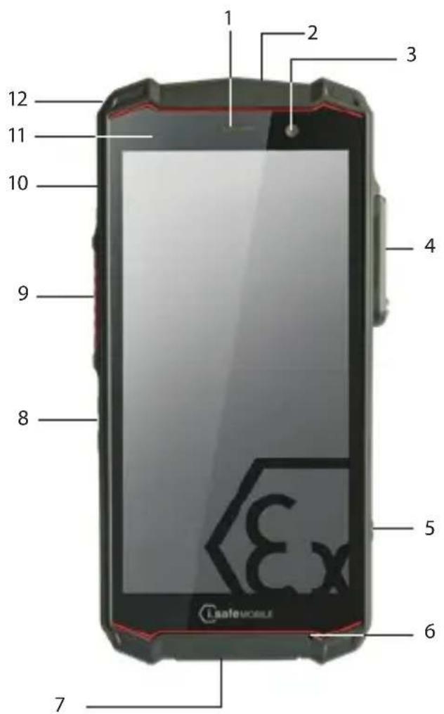
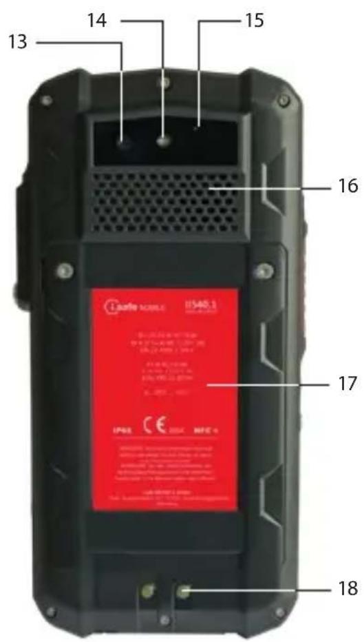
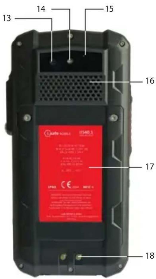
>DEVICE OVERVIEW/FUNCTIONS
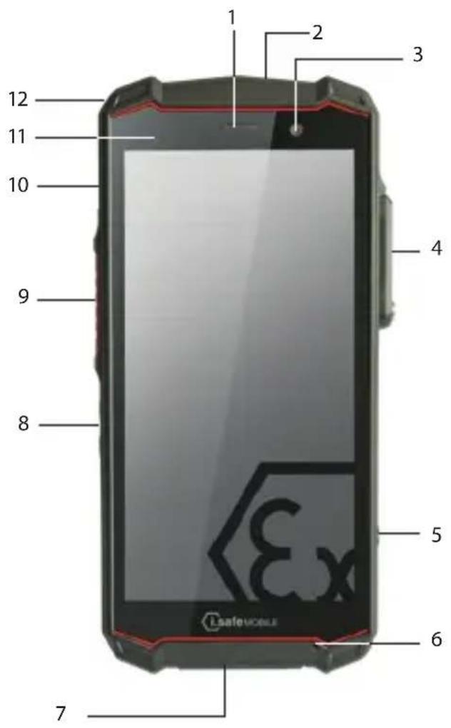
1 > LOUDSPEAKER
2> FUNCTION KEY RED: Optional function, e.g. SOS - function can be assigned via Button App (system integrated).
3>FRONT CAMERA
4) 16-PIN ISM INTERFACE: Connection for approved accessories. Also see section "Connecting approved accessories".
5> SIDE KEY RIGHT: Optional function, e.g. camera - function can be assigned via Button App (system integrated).
6) MICROPHONE
7 USB INTERFACE: Connection for the i.safe PROTECTOR 2.0 USB-C Cable or for other equipment approved by i.safe MOBILE GmbH. Also see sections "Charging" and "Connecting approved accessories".
8> LOUDNESS CONTROL: Volume up/Volume down.
9) SIDE KEY LEFT: Optional function - function can be assigned via Button App (system integrated).
10> POWER KEY: A long press switches the device on/off. A short press switches the standby mode on/off.
11> SENSORS: Proximity sensor, light sensor.
12 EYELET: Eyelet for hand strap.
13>BACK CAMERA
14>LED FLASH
15> NOISE CANCELLING: Noise cancelling microphone.
16> LOUDSPEAKER: Loudspeaker for hands-free function.
17 >BATTERY
18>CHARGING CONTACTS
> SAFETY
Read the "Safety" section of this Operating Manual carefully before using the device. If you do not follow these instructions or do not understand them, this could lead to death, severe injuries and damage to the device.
USER
Only trained users who are qualified in the use of Ex devices in explosion hazardous areas and who have read and understood this Operating Manual may use this device.
USE IN EXPLOSION HAZARDOUS AREAS
DANGER
Improper use can result in death or severe injuries!
» Only use the device in explosion hazardous areas of zones 1, 21, 2, 22, M1 and M2 or outside of explosion hazardous areas.
» Before entering an explosion hazardous area with the device,
- make sure that only approved accessories are connected to the device, see section "Connecting approved accessories",
• make sure that no gap can be seen between the two halves of the device,
• make sure the device is not damaged,
• make sure that all the labels on the device are readable,
• make sure the battery is screwed tight.
» If you use the device in an explosion hazardous area, read and follow the instructions in the "Possible User Errors" section.
» Switch off the device immediately and leave the explosion hazardous area without delay if
- malfunctions occur on the device,
- you have damaged the housing of the device,
- you have exposed the device to excessive loads,
- the labels on the device are no longer readable.
USE OUTSIDE OF EXPLOSION HAZARDOUS AREAS
DANGER
Improper use can result in death or severe injuries!
» Do not use the device in places where its use is prohibited.
» Turn off the device in clinics or other medical facilities.
» Always keep a safety distance of at least 15 cm between the device and a pacemaker or hearing aid. The device can affect the functioning of medical devices such as pacemakers and hearing aids.
» When using the device while driving a motor vehicle, be sure to comply with applicable national laws.
» Make sure you prevent the user errors described in the section entitled "Possible User Errors".
» Only charge the device as described in the "Charging" section.

CAUTION
When using earphones or headsets at the maximum volume setting, you can damage your hearing.
» First set the volume control on the device to 50 % of the maximum volume.
» Gradually adjust the volume.
NOTICE
Incorrect use can damage the device.
» Only use accessories approved by i.safe MOBILE GmbH, as described in the section on "Connecting approved accessories".
» Protect the device and the Power Adapter from strong electrical magnetic fields as for example those emitted by induction cookers or microwave ovens, for example.
» Protect the device from oils, greases and hydraulic fluids.
» Protect the unit from high mechanical hazards, strong UV radiation and highly electrically charging processes.
» Do not touch the display with sharp objects.

POSSIBLE USER ERRORS

DANGER
Improper use can result in death or severe injuries! Follow the instructions below:
» Do not modify the device structurally.
» Do not expose the device to high temperatures.
» Do not expose the device to strong UV radiation.
» Do not expose the device to processes with high electrical charges.
» Do not expose the device to aggressive acids or bases.
When working in explosion hazardous areas, please note:
» Do not loosen the screws on the device.
» Do not connect any accessories to the device.
» Do not open any interface cover.
» Do not charge the device.
» Do not open the device.
» Do not damage the device.
>SCOPE OF DELIVERY
Your device packaging contains the following:
1 × IS540.M1
1 x Battery
1 x Quick Start Manual
1 x Safety Instructions
1 x Display Protection Foil
1 x i.safe PROTECTOR 2.0 USB-C Cable
1 x Power Adapter universal (power supply unit and various country-specific adapters)
1 x Torx Screwdriver
1 x Display cleaning cloth
CELL BROADCAST
The device supports cell broadcast. Cell broadcast is a cellular service for sending messages to all recipients within a cell.
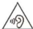
>INSTALLING THE BATTERY
DANGER
Installing the wrong battery in the device, poses a risk of explosion, which could result in death or serious injuries! Only fit the battery supplied or an approved replacement battery in the device outside of explosion hazardous areas. The approved replacement battery can be found on the website www.isafe-mobile.com/en/products
natural_image
Two views of a black flip phone showing internal components and red LED display (no text or symbols visible)» Place the battery in the battery compartment as shown.
» Hand-tighten the screws using the Torx Screwdriver provided.
» Check that the battery is seated correctly and securely.
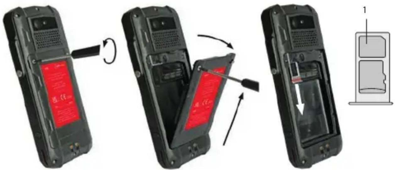
> INSERT/REMOVE SIM CARD
The device has a nano-SIM card slot and an additional eSIM. The eSIM is a non-removable, integrated digital SIM. eSIM is not supported by all mobile service provider.

DANGER
An incorrect procedure in explosion hazardous areas poses a risk of death or severe injuries! Only open the device outside of explosion hazardous areas to insert or remove the SIM card.
NOTICE
Proceeding incorrectly when inserting/removing the SIM card can damage the device and the SIM card. Switch off the device before inserting or removing a SIM card. Do not charge the device while inserting or removing a SIM card.
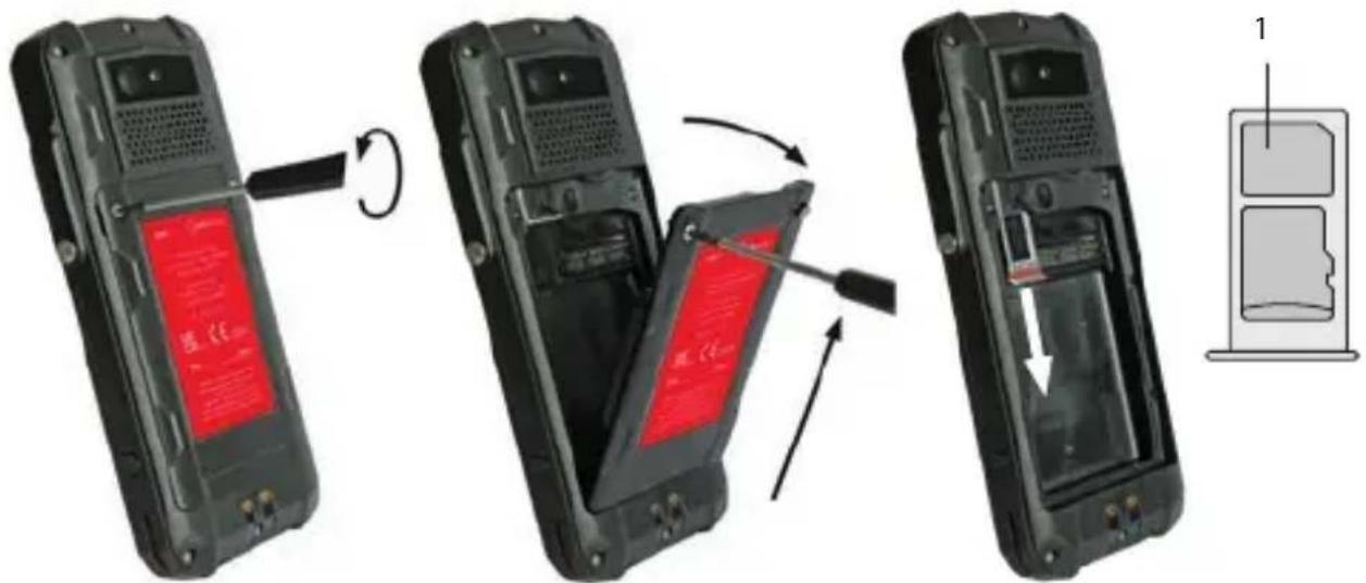
» Loosen the screws on the battery using the Torx Screwdriver provided.
» Remove the battery from the battery compartment.
» Carefully pull the card holder out of the card slot.
» Insert the SIM card into the nano-SIM card slot (1) with the gold-coloured contacts facing down.
» Carefully slide the card holder into the card slot.
»Reinstall the battery. See section "Installing the battery".
Activate eSIM
You can activate the eSIM in several ways:
- Via the Android™ Setup Wizard during initial device setup: » Scan the eSIM QR code that you have received from your service provider or manually enter the eID that you have received from your service provider.
- Via the settings menu of the smartphone:
»> Settings > Network & Internet > Mobile network (add Network) > Download SIM > scan (or manually enter) eSIM QR code that you have received from your service provider.
> INSERT/REMOVE microSD CARD

DANGER
An incorrect procedure in explosion hazardous areas poses a risk of death or severe injuries! Only open the device outside of explosion hazardous areas to insert or remove the microSD card.
NOTICE
Proceeding incorrectly when inserting/removing the microSD card can damage the device and the microSD card. Switch off the device before inserting or removing a microSD card. Do not charge the device while inserting or removing a microSD card.
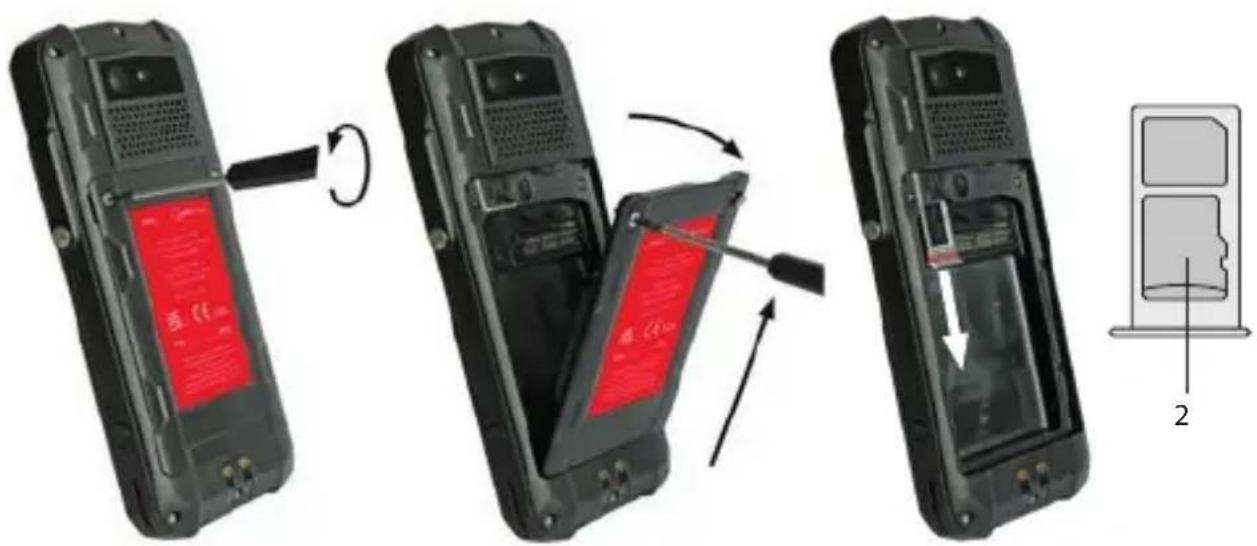
» Loosen the screws on the battery using the Torx Screwdriver provided.
» Remove the battery from the battery compartment.
» Carefully pull the card holder out of the card slot.
» Insert the microSD card into the slot provided (2) with the gold-colored contacts facing down. The device has a slot for a microSD card up to 128 GB.
» Carefully slide the card holder into the card slot.
»Reinstall the battery. See section "Installing the battery".
>CHARGING
DANGER
An incorrect procedure in explosion hazardous areas poses risk of death or severe injuries! Only charge the device outside of explosion hazardous areas. Do not charge the device in the vicinity of flammable substances.
NOTICE
Incorrect charging can cause damage to the device. Please note the following when charging:
» Only charge the device using the i.safe PROTECTOR 2.0 USB-C Cable supplied or other charging equipment approved by i.safe MOBILE GmbH.
» Only charge the device at ambient temperatures between 0 °C to +45 °C (+32 °F to +113 °F).
» Charge the device under dry indoor conditions only.
» Do not charge the device in environments dusty or humid.
Your device package contains a power supply unit, various country-specific adapters and an i.safe PROTECTOR 2.0 USB-C Cable.
» Connect the adapter suitable for your country to the power supply unit.
» Connect the i.safe PROTECTOR 2.0 USB-C Cable to the power supply unit.
» Connect the i.safe PROTECTOR 2.0 USB-C Cable to the USB interface of the device.
> SWITCHING ON/OFF
» Press and hold the power key for about 3 seconds.
» Enter the device or SIM PIN when the input dialog for the device or SIM PIN appears after switching on.
»Press and hold the power key to enter the power off menu. Select
>USING THE DEVICE
» When turning on the device for the first time, follow the instructions on the screen.
Further information on operating the device can be found at www.isafe-mobile.com/en/support/service under the menu item "FAQ".
Detailed information on operating the Android operating system can be found at: https://support.google.com/android
CONNECTING APPROVED ACCESSORIES
» Only connect accessories approved by i.safe MOBILE GmbH to the device. Accessories approved by i.safe MOBILE GmbH can be found at www.isafe-mobile.com/en/products
Approved accessories can be connected to any 16-pin ISM interface and to the USB interface.

DANGER
Improper use can result in death or severe injuries! If you need approved accessories in explosion hazardous areas, please note the following before connecting:
» Connect approved accessories to the 16-pin ISM interface of the device only outside of explosion hazardous areas.
» Never open the cover of the 16-pin ISM interface in explosion hazardous areas.
»Operate approved accessories in explosion hazardous areas only on the 16-pin ISM interface of the device. Wired connections via the USB interface are prohibited.
» Connect the plug of the accessory securely to the 16-pin ISM interface on the device.
» Only remove approved accessories from the 16-pin ISM interface outside of explosion hazardous areas.
» Close the 16-pin ISM interface with the cover provided when you are not using accessories.
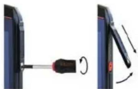
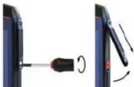
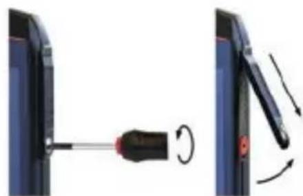
16-PIN ISM INTERFACE
natural_image
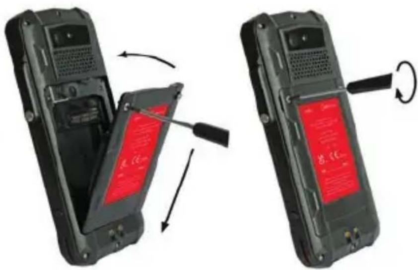
Diagram showing a screwdriver being inserted into a device, with motion arrows indicating rotation (no text or symbols present)» Loosen the screw on the 16-pin ISM interface cover using the Screwdriver included in the approved accessory package. Remove the cover as shown.
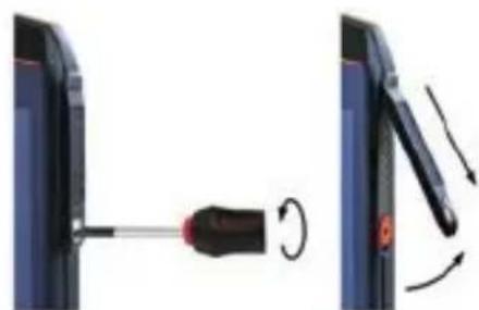
natural_image
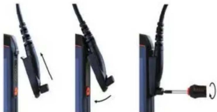
Three-step diagram showing cable fastening process: left panel with cable attachment, right panel with cable being inserted (no text or symbols)» Connect the plug of the approved accessory to the 16-pin ISM interface as shown.
» Hand-tighten the screws.
» Check that the plug is seated correctly and securely.
USB INTERFACE

DANGER
Improper use can result in death or severe injuries! Only use USB interface outside of explosion hazardous areas. Never open the cover of the USB interface in explosion hazardous areas. The USB interface is used for charging and data transfer.
» Connect approved accessories or other devices to the USB interface only by using the i.safe PROTECTOR 2.0 USB-C Cable or by using other equipment approved by i.safe MOBILE GmbH.

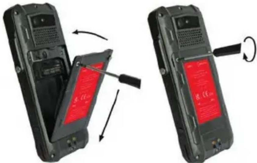
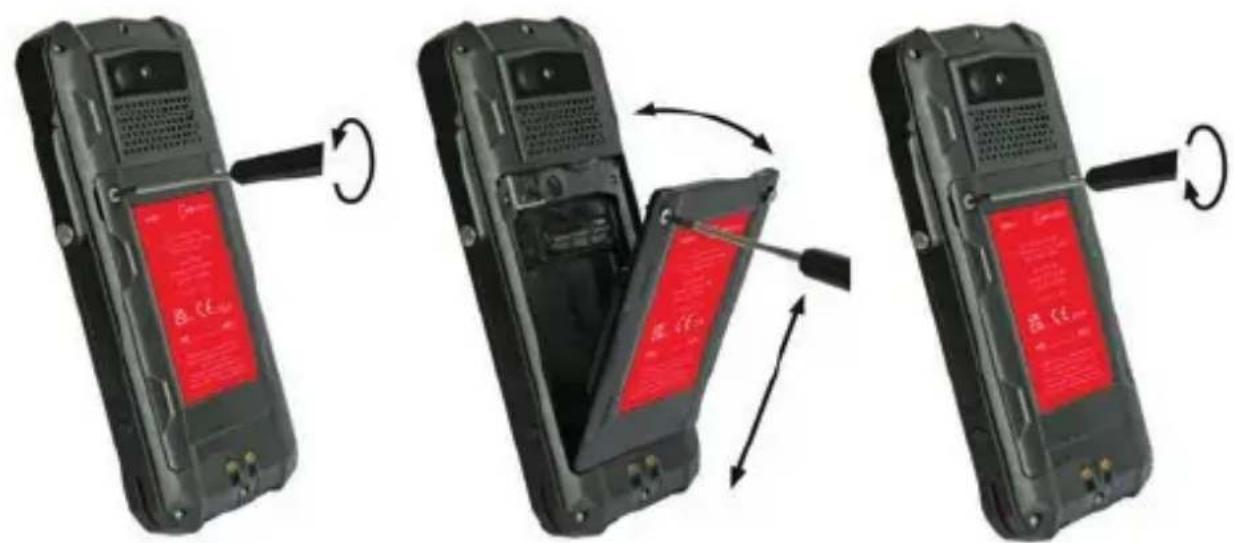
CHANGING THE BATTERY

WARNING
If you replace the battery with the wrong battery in the device, there is a risk of explosion, which could result in death or serious injuries! Only replace the battery with an approved replacement battery outside of explosion hazardous areas. An approved replacement battery can be found on the website www.isafe-mobile.com/en/products
natural_image
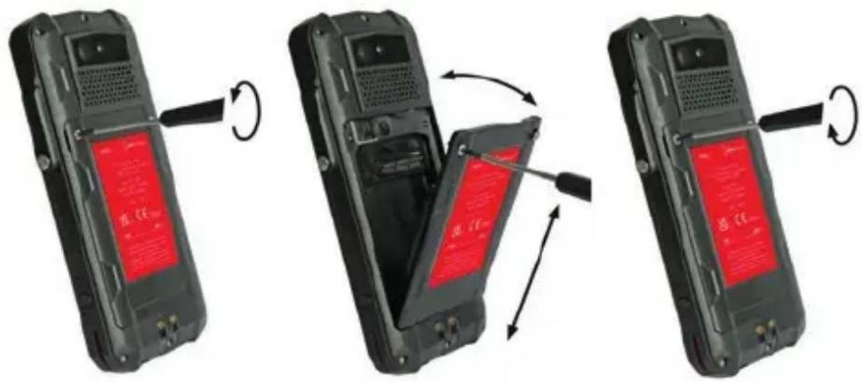
Three-step diagram showing a mobile phone's open rear panel with red LED display and black cable, demonstrating the process of rotation and battery disassembly (no text or symbols present)» Loosen the screws on the battery using the Torx Screwdriver provided.
» Remove the battery from the battery compartment as shown.
» Place the approved replacement battery in the battery compartment as shown.
» Hand-tighten the screws using the Torx Screwdriver provided.
» Check that the battery is seated correctly and securely.
POSSIBLE DEVICE PROBLEMS
You can find information on possible device problems and how to rectify them at www.isafe-mobile.com/en/support/service under the menu item "FAQ".
If you have any further questions, please contact the i.safe MOBILE GmbH repair service at www.isafe-mobile.com/en/support/service
MAINTENANCE/REPAIR
The device itself has no serviceable parts.
WARNING
Incorrect repairs present a risk of explosion or fire, which can result in death or severe injuries! Do not open the device or carry out any repairs yourself.
» Contact the i.safe MOBILE GmbH repair service at www.isafe-mobile.com/en/support/service if the device is not working normally, if the device needs to be repaired or if a replacement part is required.
RETURN SHIPMENT
Contact the i.safe MOBILE GmbH repair service at www.isafe-mobile.com/en/support/service
DISTRIBUTION PARTNER
You can find the specialist distribution partner responsible for your country at www.isafe-mobile.com/en/contact
>CLEANING
NOTICE
Incorrect cleaning can cause damage to the device. Please note the following when cleaning:
» Turn off the device before cleaning.
» Do not charge the device while cleaning.
» Do not use chemical agents for cleaning.
» Clean the device and the Power Adapter with a soft, moistened antistatic cloth.
» Clean the display screen regularly with a soft, antistatic cloth.
>STORAGE
NOTICE
Incorrect storage can cause damage to the device. Store the device at a humidity of 10 % to 60 % at the following ambient temperatures:
Up to one month: -20 °C to +45 °C (-4 °F to +113 °F)
Up to 3 months: -10 °C to +35 °C (+14 °F to +95 °F)
Over 3 months: -10 °C to +25 °C (+14 °F to +77 °F)
If you do not use the device for a longer period of time, note the following:
» Switch off the device.
» For longer storage without use, charge the device to approx. 50 % to 70 % using the i.safe PROTECTOR 2.0 USB-C Cable supplied or other charging equipment approved by i.safe MOBILE GmbH.
» Charge the device every 3 to 6 months to avoid deep discharge.
» Store it in a cool, dry place to keep the battery functional.
RECYCLING
NOTICE
Incorrect disposal of electronic products, batteries and packaging material puts the environment at risk. Please note the following when disposing of items:
» DO NOT throw away batteries with household waste.
» Always dispose electronic products, batteries and packaging material at the appropriate collection points. This way, you prevent uncontrolled waste disposal and promote the recycling of material resources.
You can obtain further information from regional waste disposal companies, state authorities or the i.safe MOBILE GmbH service centre responsible for your country or region at www.isafe-mobile.com/en/support/service
TRADEMARKS
i.safe MOBILE GmbH and the i.safe MOBILE GmbH logo are registered trademarks of the i.safe MOBILE GmbH.
Comes with the Google™ app and Google Chrome™
Google and Google Chrome are trademarks of Google LLC.
Android is a trademark of Google LLC.
All other trademarks and copyrights are the properties of their respective owners.
DEUTSCH
www.isafe-mobile.com/de/support/downloads
FCC/IC ERKLÄRUNG
www.isafe-mobile.com/de/support/downloads
EX-KENNZEICHNUNGEN
> ATEX:
Ex1 M1 Ex ia I Ma
II 2G Ex ib IIC T4 Gb
II 2D Ex ib IIIC T135°C Db
natural_image
Two views of a black flip phone showing internal components and red cover (no text or symbols visible)natural_image
Diagram showing a screwdriver being inserted into a device, with motion arrows indicating rotation (no text or symbols present)natural_image
Three-step diagram showing cable fastening and screwdriver insertion (no text or symbols)natural_image
Three-step diagram showing a mobile phone's open panel with red LED display and black buttons, demonstrating the process of rotation and battery release (no text or symbols present)www.isafe-mobile.com/en/support/downloads
PROHLÁŠENÍ FCC/IC
www.isafe-mobile.com/en/support/downloads
ZNAČENÍ SOUVISEJÍCÍ S NEBEZPEČÍM VÝBUCHU
> ATEX:
Exia I Ma
① II 2G Ex ib IIC T4 Gb
II 2D Ex ib IIIC T135°C Db
natural_image
Two views of a black flip phone showing internal components and red cover (no text or symbols visible)natural_image
Diagram showing a screwdriver being inserted into a device, with motion arrows indicating rotation (no text or symbols)natural_image
Three-step diagram showing cable fastening and screwdriver insertion (no text or symbols)www.isafe-mobile.com/en/support/downloads
FCC/IC-ERKLÆRING
FCC/IC-erklæringen findes på www.isafe-mobile.com/en/support/downloads
TIDLIGERE MÆRKNINGER
> ATEX:
Ex I M1 Ex ia I Ma
① II 2G Ex ib IIC T4 Gb
II 2D Ex ib IIIC T135°C Db
natural_image
Two black flip-flops with red internal bands, showing a device's open and closed states, with no visible text or symbols.natural_image
Diagram showing a screwdriver inserted into a U-shaped device, with motion arrows indicating rotation (no text or symbols)natural_image
Three-step diagram showing cable fastening and screwdriver insertion (no text or symbols)www.isafe-mobile.com/en/products
natural_image
Two views of a black flip phone showing internal components and battery casing (no text or symbols visible)natural_image
Diagram showing a screwdriver being inserted into a device, with motion arrows indicating rotation (no text or symbols present)natural_image
Three-step diagram showing cable fastening and mounting mechanism (no text or symbols)natural_image
Three-step illustration of a mobile phone's open rear panel showing red LED display and battery casing (no text or symbols)www.isafe-mobile.com/en/support/downloads
FCC-/IC-LAUSUNTO
www.isafe-mobile.com/en/support/downloads
EX-MERKINNÄT
> ATEX:
Ex I M1 Ex ia I Ma
II 2G Ex ib IIC T4 Gb
Ea II 2D Ex ib IIIC T135°C Db
natural_image
Two views of a black flip phone showing internal components and red screen display (no text or symbols visible)natural_image
Diagram showing a screwdriver being inserted into a device, with motion arrows indicating rotation (no text or symbols present)natural_image
Three-step diagram showing cable fastening process: left panel with cable attachment, right panel with cable being inserted (no text or symbols)DÉCLARATION DE CONFORMITÉ UE
Certification CE: 2004
IECEx:
Ex ia I Ma
Ex ib IIC T4 Gb
Ex ib IIIC T135°C Db
Certificat IECEx: IECEx EPS 23.0002X
> Plage de temperature:
-20°C ... +55°C (EN/IEC 60079-0)
-10°C ... +55°C (EN/IEC 62368-1)
> Fabrique par:
i.safe MOBILE GmbH
i_Park Tauberfranken 10
97922 Lauda-Koenigshofen
Allemagne
SYNOPTIQUE DES APPAREILS/FONCTIONS
natural_image
Two views of a black flip phone showing internal components and a red LED display (no text or symbols visible)MISE EN MARCHE/ARRÊT
INTERFACE 16-PIN ISM
natural_image
Diagram showing a screwdriver being inserted into a device, with motion arrows indicating rotation (no text or symbols present)natural_image
Three-step diagram showing cable fastening process: left panel with plug, right panel with cable being inserted (no text or symbols)natural_image
Three-step diagram showing a mobile phone's open rear panel with red LED display and black buttons, demonstrating the process of rotation and battery state (no text or symbols present)natural_image
Two views of a black flip phone showing internal components and red cover (no text or symbols visible)natural_image
Diagram showing a screwdriver being inserted into a device, with motion arrows indicating rotation (no text or symbols present)natural_image
Three-step diagram showing cable fastening and screwdriver insertion (no text or symbols)natural_image
Three-step diagram showing a device being opened, with red LED display and black buttons, indicating rotation or disassembly (no text or symbols present)www.isafe-mobile.com/en/support/downloads
DICHIARAZIONE FCC/IC
www.isafe-mobile.com/en/support/downloads
USO IN AREE A RISCHIO DI ESPLOSIONE
PERICOLO
USO FUORI DALLE AREE A RISCHIO DI ESPLOSIONE
PERICOLO
natural_image
Two views of a black flip phone showing internal components and a red LED display (no text or symbols visible)natural_image
Diagram showing a screwdriver being inserted into a device, with rotation arrows indicating motion (no text or symbols)natural_image
Three-step diagram showing cable fastening and mounting mechanism (no text or symbols)www.isafe-mobile.com/en/support/downloads
FCC/IC-VERKLARING
www.isafe-mobile.com/en/support/downloads
EX-MARKERINGEN
> ATEX:
① I M1 Ex ia I Ma
II 2G Ex ib IIC T4 Gb
II 2D Ex ib IIIC T135°C Db
natural_image
Two views of a black flip phone showing internal components and red screen display (no text or symbols visible)natural_image
Diagram showing a screwdriver being inserted into a device, with motion arrows indicating rotation (no text or symbols present)natural_image
Three-step diagram showing cable fastening process: left panel with cable attachment, right panel with cable fastening and clamping (no text or symbols)www.isafe-mobile.com/en/support/downloads
FCC/IC UTTALELSE
FCC/IC-erklæringen finner du på www.isafe-mobile.com/en/support/downloads
EX-MERKING
> ATEX:
④ I M1 Ex ia I Ma
II 2G Ex ib IIC T4 Gb
II 2D Ex ib IIIC T135°C Db
natural_image
Two black flip-flops with red and black panels, showing a device being opened and then closed, with no visible text or symbols.natural_image
Diagram showing a screwdriver inserted into a U-shaped device, with motion arrows indicating rotation (no text or symbols)natural_image
Three-step diagram showing cable fastening and disassembly process (no text or symbols)natural_image
Three-step diagram showing a mobile phone's open rear panel with red LED display and black cable, demonstrating battery state rotation (no text or symbols)VEDLIKEHOLD/REPARASJON
natural_image
Two views of a black flip phone showing internal components and battery cover changes (no text or symbols visible)natural_image
Diagram showing a screwdriver inserted into a device, with rotation arrows indicating motion (no text or symbols)natural_image
Three-step diagram showing a cable being inserted into a plug, with no visible text or symbols.www.isafe-mobile.com/en/support/service.
natural_image
Two views of a black flip phone showing internal components and red cover (no text or symbols visible)» Coloque a bateria no compartimento da bateria, como indicado.
» Aperte os parafusos manualmente com a chave de fendas Torx fornecida.
» Verifique se a bateria está colocada de forma correta e segura.
INTERFACE 16-PIN ISM
natural_image
Diagram showing a screwdriver being inserted into a device, with motion arrows indicating rotation (no text or symbols)natural_image
Three-step diagram showing cable fastening and screwdriver insertion (no text or symbols)» Ligue a ficha do acessório aprovado à interface 16-pin ISM, como indicado.
» Aperte os parafusos manualmente.
» Verifique se a ficha está colocada de forma correta e segura.
INTERFACE USB

PERIGO
www.isafe-mobile.com/en/support/downloads
www.isafe-mobile.com/en/support/downloads
MARCAS
> ATEX:
Ex1 M1 Ex ia I Ma
II 2G Ex ib IIC T4 Gb
II 2D Ex ib IIIC T135°C Db
www.isafe-mobile.com/en/products
natural_image
Two views of a black flip phone showing internal components and battery casing (no text or symbols visible)» Posicione a bateria no compartimento de bateria conforme exibido.
» Aperte os parafusos usando a chave Torx fornecida.
» Verifique se a bateria está encaixada corretamente e com firmeza.
>INSERIR/REMOVER CARTÃO SIM
INTERFACE 16-PIN ISM
natural_image
Diagram showing a screwdriver being inserted into a device, with motion arrows indicating rotation (no text or symbols)natural_image
Three-step diagram showing cable fastening and disassembly process (no text or symbols)» Conecte o plugue do acessório aprovado à interface 16-pin ISM, conforme exibido.
» Aperte os parafusos.
» Verifique se o plugue está encaixado corretamente e com firmeza.
INTERFACE USB

PERIGO
www.isafe-mobile.com/en/products
natural_image
Three-step illustration of a mobile phone's open rear panel showing red LED display and battery casing (no text or symbols)» Solte os parafusos da bateria utilizando a chave Torx fornecida.
»Remova a bateria do compartimento de bateria, conforme exibido.
» Posicione a bateria substituta aprovada no compartimento de bateria, conforme exibido.
» Aperte os parafusos usando a chave Torx fornecida.
» Verifique se a bateria está encaixada corretamente e com firmeza.
POSSÍVEIS PROBLEMAS DO DISPOSITIVO
natural_image
Two views of a black flip phone showing internal components and a red-labeled screen (no text or symbols visible)natural_image
Diagram showing a screwdriver inserted into a device, with rotation arrows indicating motion (no text or symbols)natural_image
Three-step diagram showing cable fastening process: left panel with cable attachment, right panel with cable insertion and rotation (no text or symbols)natural_image
Three-panel illustration of a mobile phone showing the open and closed states of its back panel, with red LED display and black buttons (no text or symbols visible)natural_image
Two views of a black flip phone showing internal components and battery cover (no text or symbols visible)natural_image
Diagram showing a screwdriver inserted into a U-shaped device, with motion arrows indicating rotation (no text or symbols present)natural_image
Three-step diagram showing cable fastening and screwdriver insertion (no text or symbols)natural_image
Three-step illustration of a mobile phone's open rear panel showing battery, cable, and scroll (no text or symbols)www.isafe-mobile.com/en/support/downloads
IZJAVA FCC-A/IC-A
Izjavu FCC-a/IC-a možete pronaći na www.isafe-mobile.com/en/support/downloads
EX OZNAKE
> ATEX:
① I M1 Ex ia I Ma
II 2G Ex ib IIC T4 Gb
II 2D Ex ib IIIC T135°C Db
Certifikat o ispitivanju EU tipa:
EPS 23 ATEX 1 012 X
Oznaka CE: 2004
>IECEx:
Ex ia I Ma
Ex ib IIC T4 Gb
Ex ib IIIC T135°C Db
IECEx certifikat: IECEx EPS 23.0002X
> Raspon temperature:
-20°C ... +55°C (EN/IEC 60079-0)
-10°C ... +55°C (EN/IEC 62368-1)
> Proizvođač:
i.safe MOBILE GmbH
i_Park Tauberfranken 10
97922 Lauda-Koenigshofen
Njemačka
> PREGLED/FUNKCIJE UREĐAJA

1 > ZVUČNIK
2) CRVENA FUNKCIJSKA TIPKA: Opcija funkcije, npr. SOS - funkcija se može dodijeliti putem Button App (integriran sustav).
3 >PREDNJAKAMERA
4) 16-PIN ISM SUČELJE: Spajanje za odobreni pribor. Također pogledajte odlomak „Spaja- nje odobrenog pribora“.
5> BOČNA TIPKA UDESNO: Opcija funkcije, npr. kamera - funkcija se može dodijeliti putem Button App (integriran sustav).
6) MIKROFON
7> USB SUČELJE: Priključak za kabel i.safe PROTECTOR 2.0 USB-C ili drugu opremu koji je odobrio i.safe MOBILE GmbH. Također pogledajte odlomke „Punjenje“ i „Spajanje odobrenog pribora“.
8) UPRAVLJANJE GLASNOĆOM: Povećanje glasnoće/smanjenje glasnoće.
9) BOČNA TIPKA ULIJEVO: Opcija funkcije - funkcija se može dodijeliti putem Button App (integriran sustav).
10) TIPKA ZA UKLJUČIVANJE I ISKLJUČIVANJE: Dugi pritisak uključuje/isključuje uređaj. Kratki pritisak uključuje/isključuje način rada za pripravnost.
11) SENZORI: Senzor blizine, senzor svjetlosti.
12) UŠICA: ušica za pričvršćenje trake za nošenje.
13>STRAŽNJAKAMERA
14>LEDBLJESKALICA
15> OTKAZIVANJE BUKE: Mikrofon za otkazivanje buke.
16> ZVUČNIK: Zvučnik za rad bez ruku.
17) BATERIJA
18 KONTAKTZAPUNJENJE
SIGURNOST
natural_image
Two views of a black flip phone showing internal components and red cover (no text or symbols visible)» Postavite bateriju u odjeljak za bateriju prema prikazu.
» Ručno zategnite vijke isporučenim Torx odvijačem.
» Provjerite da je baterija pravilno učvršćena.
UMETANJE/UKLANJANJE SIM KARTICE
Uređaj ima utor za nano SIM karticu i dodatnu eSIM karticu. eSIM kartica je nezamjenjiva, integrirana, digitalna eSIM kartica. Karticu eSIM ne podržava svaki pružatelj usluga mobilne telefonije.

OPASNOST
Neodgovarajući postupak u područjima ugroženima eksplozijom predstavlja opasnost od smrti ili teških ozljeda! Otvarajte uređaj samo izvan područja ugroženih eksplozijom da biste umetnuli ili uklonili SIM karticu.
NAPOMENA
Neodgovarajući postupak pri umetanju/uklanjanju SIM kartice može oštetiti uređaj i SIM karticu. Isključite uređaj prije umetanja ili uklanjanja SIM kartice. Ne punite uređaj za vrijeme umetanja ili uklanjanja SIM kartice.
» Otpustite vijke na bateriji isporučenim Torx odvijačem.
» Uklonite bateriju iz odjeljka za bateriju.
» Pažljivo izvucite nosač kartice iz utora za karticu.
» Umetnite SIM karticu u utor za nano SIM karticu (1) tako da kontakti zlatne boje gledaju prema dolje.
» Gurnite nosač kartice pažljivo u utor za karticu.
» Ponovno ugradite bateriju. Pogledajte odlomak „Ugradnja baterije“.
AKTIVIRAJTE ESIM
» Otpustite vijke na bateriji isporučenim Torx odvijačem.
» Uklonite bateriju iz odjeljka za bateriju.
» Pažljivo izvucite nosač kartice iz utora za karticu.
» Umetnite mikro SD karticu u pripadajući utor (2) tako da kontakti zlatne boje gledaju prema dolje. Uređaj ima a utor za microSD karticu do 128 GB.
» Gurnite nosač kartice pažljivo u utor za karticu.
» Ponovno ugradite bateriju. Pogledajte odlomak „Ugradnja baterije“.
PUNJENJE
OPASNOST
natural_image
Diagram showing a screwdriver being inserted into a device, with motion arrows indicating rotation (no text or symbols present)natural_image
Three-step diagram showing cable installation steps: wire insertion, compression, and disassembly (no text or symbols)» Spojite utikač odobrenog pribora na 16-pin ISM sučelje prema prikazu.
» Ručno zategnite vijke.
» Provjerite da je utikač pravilno učvršćen.
USB SUČELJE

OPASNOST
natural_image
Three-step diagram showing the open and closed views of a mobile phone's front panel, with no visible text or symbols.» Otpustite vijke na bateriji isporučenim Torx odvijačem.
» Uklonite bateriju iz odjeljka za bateriju prema prikazu.
» Postavite odobrenu zamjensku bateriju u odjeljak za bateriju prema prikazu.
» Ručno zategnite vijke isporučenim Torx odvijačem.
» Provjerite da je baterija pravilno učvršćena.
MOGUĆI PROBLEMI S UREĐAJEM
www.isafe-mobile.com/en/support/downloads
VYHLÁSENIE FCC/IC
Vyhlásenie FCC/IC nájdete na www.isafe-mobile.com/en/support/downloads
OZNAČENIA SÚVISIACE S NEBEZPEČENSTVOM VÝBUCHU
> ATEX:
① I M1 Ex ia I Ma
II 2G Ex ib IIC T4 Gb
II 2D Ex ib IIIC T135°C Db
natural_image
Two black flip-flops with red and black panels, showing internal components and a scroll wheel (no text or symbols visible)https://support.google.com/android
PRIPOJENIE SCHVÁLENÉHO PRÍSLUŠENSTVA
» K zariadeniu pripájajte iba príslušenstvo schválené spoločnostou i.safe MOBILE GmbH. Príslušenstvo schválené spoločnostou i.safe MOBILE GmbH nájdete na www.isafe-mobile.com/en/products
natural_image
Diagram showing a screwdriver being inserted into a device, with motion arrows indicating rotation (no text or symbols)natural_image
Three-step diagram showing cable fastening and mounting mechanism (no text or symbols)natural_image
Three-step diagram showing a mobile phone's open rear panel with red LED display and black buttons, indicating battery state changes (no text or symbols present)www.isafe-mobile.com/en/support/downloads
FCC/IC ИЗJABA
natural_image
Two views of a black flip phone showing internal components and red LED display (no text or symbols visible)natural_image
Diagram showing a screwdriver being inserted into a device, with motion arrows indicating rotation (no text or symbols present)natural_image
Three-step diagram showing cable fastening and screwdriver insertion (no text or symbols)natural_image
Two views of a black flip phone showing internal components and a red screen with text (no visible text or symbols)natural_image
Diagram showing a screwdriver being inserted into a device, with motion arrows indicating rotation (no text or symbols present)natural_image
Three-step diagram showing cable fastening process: left panel with cable attachment, right panel with cable disassembly and angle marking (no text or symbols)natural_image
Two views of a black flip phone showing internal components and battery casing (no text or symbols visible)natural_image
Diagram showing a screwdriver being inserted into a device, with motion arrows indicating rotation (no text or symbols present)natural_image
Three-step diagram showing cable installation steps: straight, curved, and twisted (no text or symbols)natural_image
Three-step illustration of a mobile phone's open rear door, showing red and black casing with scroll arrows indicating rotation (no text or symbols)natural_image
Two views of a black flip phone showing internal components and red cover (no text or symbols visible)如图所示,将电池放入电池仓中。
使用随附的内梅花螺丝刀手动拧紧螺钉。
》检查电池已正确、牢固放置。
插入/移除 SIM 卡
natural_image
Diagram showing a screwdriver being inserted into a device, with rotation arrows indicating motion (no text or symbols)natural_image
Three-step diagram showing cable fastening and mounting mechanism (no text or symbols)www.isafe-mobile.com/cn/support/downloads
www.isafe-mobile.com/en/support/downloads
www.isafe-mobile.com/en/support/service
www.isafe-mobile.com/en/support/downloads
نطاق درجة الحرارة
-20°C ... +55°C (EN/IEC 60079-0)
-10°C ... +55°C (EN/IEC 62368-1)
المُصْع:
i.safe MOBILE GmbH
i Park Tauberfranken 10
Lauda-Koenigshofen 97922
اللمانيا
natural_image
Two views of a mobile phone showing red and black casing with battery, connected by arrows indicating rotation (no text or symbols visible)natural_image
Two-step diagram showing a switch being inserted into a battery, with the second step showing a screwdriver inserted (no text or symbols present)natural_image
Three-step diagram showing a cable being inserted into a device, with no visible text or symbols.FOR FURTHER QUESTIONS PLEASE CONTACT OUR SERVICE CENTRE:
» i.safe MOBILE GmbH, i_Park Tauberfranken 10, 97922 Lauda-Koenigshofen, Germany
» support@isafe-mobile.com
» https://support.isafe-mobile.com
WWW.ISAFE-MOBILE.COM


- CONTENTS
- ENGLISH
- >READ AND UNDERSTAND THE INSTRUCTIONS
- PROTECT YOUR LIFE AND READ THE OPERATING MANUAL
- INTENDED USE
- WARRANTY
- EU DECLARATION OF CONFORMITY
- FCC/IC STATEMENT
- EX MARKINGS
- > ATEX:
- >IECEx:
- > ANZEx (Australian/New Zealand):
- > IA (South Africa):
- > Temperature range:
- Manufactured by:
- i.safe MOBILE GmbH
- >DEVICE OVERVIEW/FUNCTIONS
- > SAFETY
- USER
- USE IN EXPLOSION HAZARDOUS AREAS
- DANGER
- USE OUTSIDE OF EXPLOSION HAZARDOUS AREAS
- CAUTION
- NOTICE
- POSSIBLE USER ERRORS
- When working in explosion hazardous areas, please note:
- >SCOPE OF DELIVERY
- CELL BROADCAST
- >INSTALLING THE BATTERY
- > INSERT/REMOVE SIM CARD
- Activate eSIM
- > INSERT/REMOVE microSD CARD
- >CHARGING
- > SWITCHING ON/OFF
- >USING THE DEVICE
- CONNECTING APPROVED ACCESSORIES
- 16-PIN ISM INTERFACE
- USB INTERFACE
- CHANGING THE BATTERY
- WARNING
- POSSIBLE DEVICE PROBLEMS
- MAINTENANCE/REPAIR
- RETURN SHIPMENT
- DISTRIBUTION PARTNER
- >CLEANING
- >STORAGE
- RECYCLING
- TRADEMARKS
- DEUTSCH
- FCC/IC ERKLÄRUNG
- EX-KENNZEICHNUNGEN
- PROHLÁŠENÍ FCC/IC
- ZNAČENÍ SOUVISEJÍCÍ S NEBEZPEČÍM VÝBUCHU
- FCC/IC-ERKLÆRING
- TIDLIGERE MÆRKNINGER
- FCC-/IC-LAUSUNTO
- EX-MERKINNÄT
- DÉCLARATION DE CONFORMITÉ UE
- IECEx:
- > Plage de temperature:
- > Fabrique par:
- SYNOPTIQUE DES APPAREILS/FONCTIONS
- MISE EN MARCHE/ARRÊT
- INTERFACE 16-PIN ISM
- DICHIARAZIONE FCC/IC
- USO IN AREE A RISCHIO DI ESPLOSIONE
- PERICOLO
- USO FUORI DALLE AREE A RISCHIO DI ESPLOSIONE
- FCC/IC-VERKLARING
- EX-MARKERINGEN
- FCC/IC UTTALELSE
- EX-MERKING
- VEDLIKEHOLD/REPARASJON
- INTERFACE USB
- PERIGO
- MARCAS
- >INSERIR/REMOVER CARTÃO SIM
- POSSÍVEIS PROBLEMAS DO DISPOSITIVO
- IZJAVA FCC-A/IC-A
- EX OZNAKE
- > Raspon temperature:
- > Proizvođač:
- > PREGLED/FUNKCIJE UREĐAJA
- SIGURNOST
- UMETANJE/UKLANJANJE SIM KARTICE
- OPASNOST
- NAPOMENA
- AKTIVIRAJTE ESIM
- PUNJENJE
- USB SUČELJE
- MOGUĆI PROBLEMI S UREĐAJEM
- VYHLÁSENIE FCC/IC
- OZNAČENIA SÚVISIACE S NEBEZPEČENSTVOM VÝBUCHU
- PRIPOJENIE SCHVÁLENÉHO PRÍSLUŠENSTVA
- FCC/IC ИЗJABA
- 插入/移除 SIM 卡
Brand : i.safe Mobile
Model : IS540.M1
Category : Smartphone