DW738 - Saw DEWALT - Free user manual and instructions
Find the device manual for free DW738 DEWALT in PDF.

User questions about DW738 DEWALT
0 question about this device. Answer the ones you know or ask your own.
Ask a new question about this device
Download the instructions for your Saw in PDF format for free! Find your manual DW738 - DEWALT and take your electronic device back in hand. On this page are published all the documents necessary for the use of your device. DW738 by DEWALT.
USER MANUAL DW738 DEWALT
English (original instructions) 15
text_image
Technical diagram of a sewing machine with numbered parts for identification and assembly reference.Fig. B
text_image
Technical diagram of a mechanical assembly with numbered parts for identificationnatural_image
Line drawing of a mechanical device with a vertical frame and metal base (no text or symbols)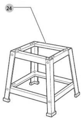
natural_image
Line drawing of a four-legged metal frame structure with a labeled component (no text or symbols present)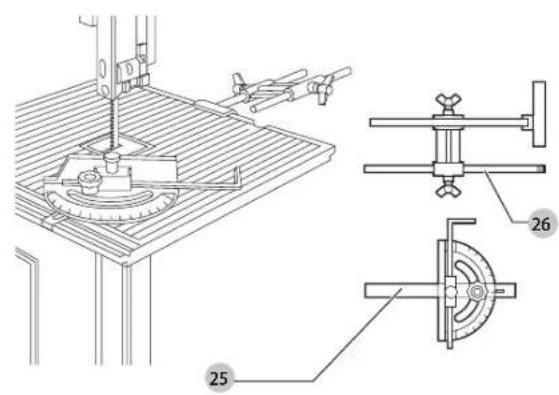
text_image
Technical diagram of a mechanical assembly with labeled parts and cross-sectional viewsFig. D1 Fig. D2
natural_image
Technical line drawing of a mechanical component with no visible text or symbols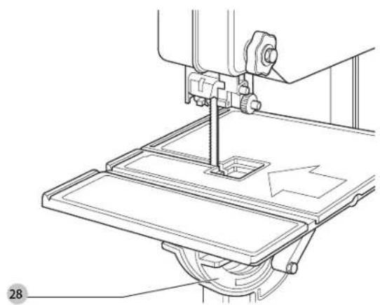
natural_image
Technical line drawing of a mechanical assembly with no visible text or symbolsFig. D3 Fig. D4
text_image
29 29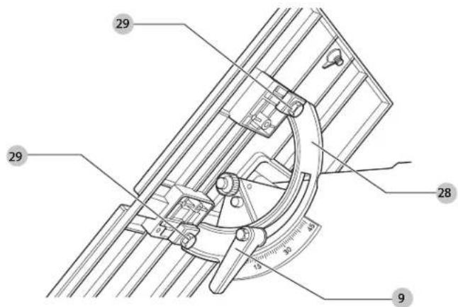
text_image
Technical diagram of a mechanical device with numbered components and measurement markingsFig. D5 Fig. D6
natural_image
Technical line drawing of a mechanical assembly with a diagonal bar and labeled component '4' (no text or symbols beyond label)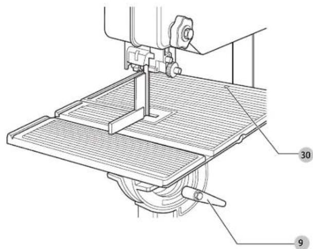
text_image
Technical diagram of a sewing machine with labeled parts 9 and 30Dansk
text_image
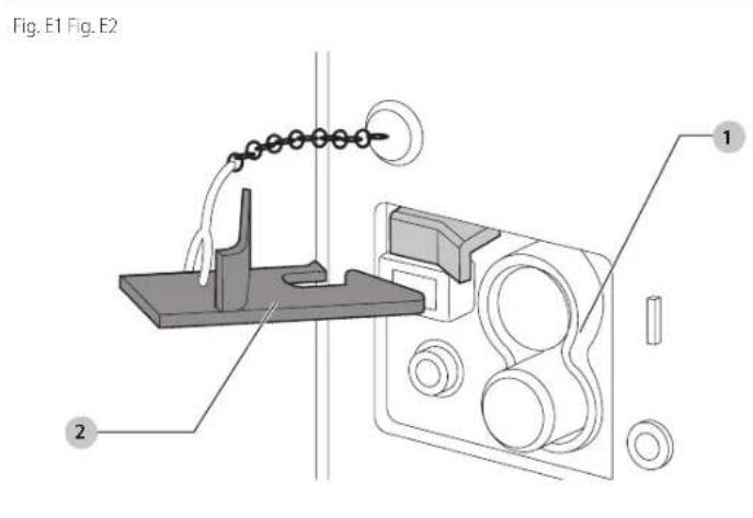
Fig. E1 Fig. E2 1 2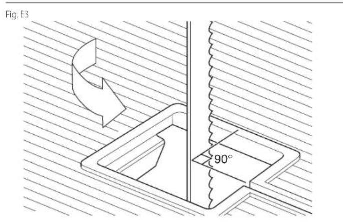
text_image
Fig. B3 90°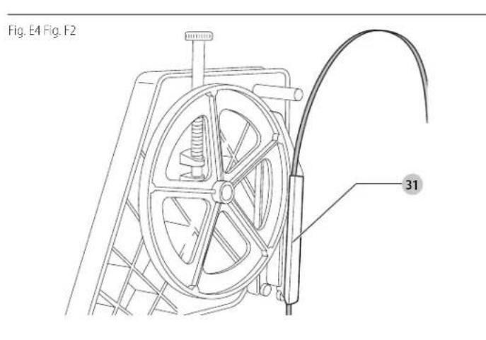
text_image
Fig. E4 Fig. F2 31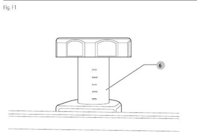
text_image
Fig. F1 6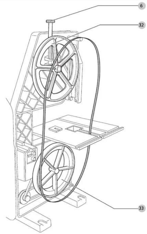
text_image
Technical diagram of a mechanical device with numbered components labeled 33, 6, and 32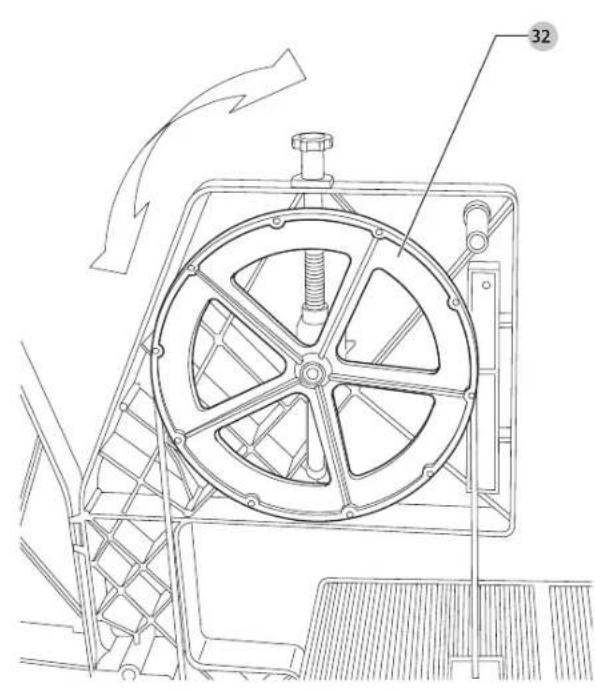
natural_image
Technical line drawing of a mechanical device with labeled component 32, showing internal components and motion arrows (no text or symbols beyond label)Dansk
text_image
Technical diagram of a mechanical assembly with labeled parts 37 and 38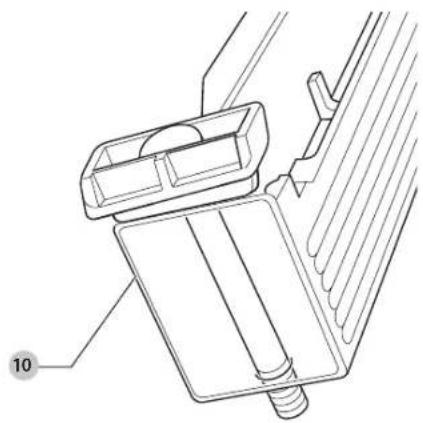
natural_image
Technical line drawing of a mechanical assembly with no visible text or symbolsFig. J3
text_image
39 10Fig. J4
natural_image
Technical line drawing of a mechanical assembly with no visible text or symbolsFig. J5 Fig. K
natural_image
Technical line drawing of a mechanical assembly with no visible text or symbols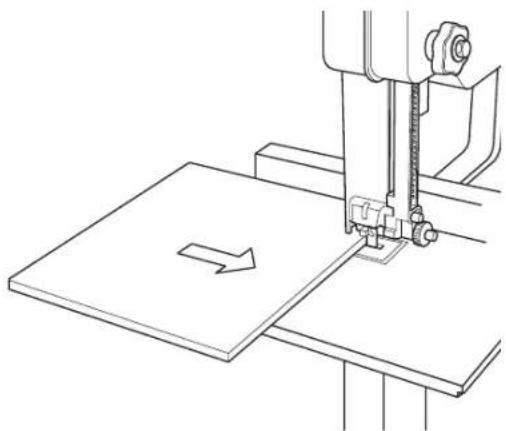
natural_image
Technical line drawing of a sewing machine needle stitching a flatboard with an arrow indicating direction (no text or symbols)Fig. L

natural_image
Technical line drawing of a mechanical clamp or clamp device with no visible text or symbolsBÄNDSAV DW738, DW739
Tillykke!
BANDSÄGE DW738, DW739
1 Mutternschlüssel (10–13 mm)
You have chosen a DFWALT tool. Years of experience, thorough product development and innovation make DFWALT one of the most reliable partners for professional power tool users.
Technical Data
| DW738 DW739 | |||
| Voltage V | c | 230 230 | |
| UK & Ireland V | c | 230/115 230/115 | |
| Type 3 3 | |||
| Power input W 750 750 | |||
| Cutting speed m/min 330/800 330-800 | |||
| Motor speed min | 1 | 2830 2830 | |
| Max. cutting height mm 155 155 | |||
| Max. cutting width mm 310 310 | |||
| Table size | mm | 380 x 380 | 380 x 380 |
| Table inclination | 0 45° | 0 45° | |
| Overall height | mm 970 970 | ||
| Overall width | mm 510 510 | ||
| Overall depth | mm 660 660 | ||
| Weight | kg | 23 | 23 |
| L_ W (sound pressure) | dB(A) | 92.0 | 92.0 |
| L_ W (sound pressure uncertainty) | dB(A) | 3.3 | 3.3 |
| I_ W W (sound power) | dB(A) | 105.0 | 105.0 |
| K_ W W (sound power uncertainty) | dB(A) | 4.0 | 4.0 |
nOtE: This device is intended for the connection to a power supply system with maximum permissible system impedance Zmax of 0.25 OhM at the interface point (power service box) of user's supply.
The user has to ensure that this device is connected only to a power system which fulfils the requirement above. If necessary, the user can ask the public power supply company for the system impedance at the interface point.
EC-Declaration of Conformity
Machinery Directive

Bandsaw
DW738, DW739
DLWALT declares that these products described under Technical Data are in compliance with: 2006/12/EC, EN61029-1:2009 + A11:2010, EN61029-2:5:2011 + A11:2015.
These products also comply with Directive 2014/30/EU and 2011/65/EU. For more information, please contact DEWALT at the following address or refer to the back of the manual.
The undersigned is responsible for compilation of the technical file and makes this declaration on behalf of DrWALT.

Markus Rompel
Vice President of Engineering, PTE-Europe
D-65510, Idstein, Germany
20.02.2019

WARNING: To reduce the risk of injury, read the instruction manual.
Definitions: Safety Guidelines
The definitions below describe the level of severity for each signal word. Please read the manual and pay attention to these symbols.

DANGER: Indicates an imminently hazardous situation which, if not avoided, will result in death or serious injury.

WARNING: Indicates a potentially hazardous situation which, if not avoided, could result in death or serious injury.

CAUTION: Indicates a potentially hazardous situation which, if not avoided, may result in minor or moderate injury.
NOTICE: Indicates a practice not related to personal injury which, if not avoided, may result in property damage.

Denotes risk of electric shock.

Denotes risk of fire.
General Safety Instructions

WARNING: When using electric tools basic safety precautions should always be followed to reduce the risk of fire, electric shock and personal injury including the following.
Read all of these instructions before attempting to operate this product and save these instructions.
SAVE THIS MANUAL FOR FUTURE REFERENCE
1. Keep work area clear.
Cluttered areas and benches invite injuries.
2. Consider work area environment.
- Do not expose the tool to rain. Do not use the tool in damp or wet conditions. Keep the work area well lit (250 - 300 Lux). Do not use the tool where there is a risk of causing fire or explosion, e.g. in the presence of flammable liquids and gases.
3. Guard against electric shock.
- Avoid body contact with earthed surfaces (e.g., pipes, radiators, cookers and refrigerators). When using the tool under extreme conditions (e.g., high humidity, when metal swarf is being produced, etc.), electric safety can be improved by inserting an isolating transformer or a (FI) earth-leakage circuit-breaker.
4. Keep other persons away.
- Do not let persons, especially children, not involved with the work, touch the tool or the extension cord and keep them away from the work area.
5. Store idle tools.
- When not in use, tools must be stored in a dry place and locked up securely, out of reach of children.
6. Do not force the tool.
- It will do the job better and safer at the rate to which it was intended.
7. Use the right tool.
- Do not force small tools to do the job of a heavy duty tool. Do not use tools for purposes not intended; for example do not use circular saws to cut tree limbs or logs.
8. Dress properly.
- Do not wear loose clothing or jewellery, as these can be caught in moving parts. Non-skid footwear is recommended when working outdoors. Wear protective hair covering to contain long hair.
9. Use protective equipment.
- Always use safety glasses. Use a face or dust mask if working operations create dust or flying particles. If these particles might be considerably hot, also wear a heat-resistant apron. Wear ear protection at all times. Wear a safety helmet at all times.
10. Connect dust extraction equipment.
If devices are provided for the connection of dust extraction and collection facilities, ensure that these are connected and properly used.
11. Do not abuse the cord.
- Never yank the cord to disconnect if from the socket. Keep the cord away from heat, oil and sharp edges. Never carry the tool by its own cord.
12. Secure work.
Where possible use clamps or a vice to hold the work. It is safer than using your hand and it frees both hands to operate the tool.
13. Do not overreach.
- Keep proper footing and balance at all times.
14. Maintain tools with care.
Keep cutting tools sharp and clean for better and safer performance. Follow instructions for lubricating and changing accessories. Inspect tools periodically and if damaged have them repaired by an authorised service facility. Keep handles dry, clean and free from oil and grease.
15. Disconnect tools.
When not in use, before servicing and when changing accessories such as blades, bits and cutters, disconnect tool from the power supply.
16. Remove adjusting keys and wrenches.
- Form the habit of checking to see that adjusting keys and wrenches are removed from the tool before operating the tool.
17. Avoid unintentional starting.
- Do not carry the tool with a finger on the switch. Be sure that the tool is in the "off" position before plugging in.
18. Use outdoor extension leads.
Before use, inspect the extension cable and replace if damaged. When the tool is used outdoors, use only extension cords intended for outdoor use and marked accordingly.
19. Stay alert.
- Watch what you are doing. Use common sense. Do not operate the tool when you are tired or under the influence of drugs or alcohol.
20. Check for damaged parts.
- Before use, carefully check the tool and mains cable to determine that it will operate properly and perform its intended function. Check for alignment of moving parts, binding of moving parts, breakage of parts, mounting and any other conditions that may affect its operation. A guard or other part that is damaged should be properly repaired or replaced by an authorized service centre unless otherwise indicated in this instruction manual. Have any damaged or defective switches replaced by an authorised service center. Do not use the tool if the switch does not turn it on and off. Never attempt any repairs yourself.
WARNING: The use of any accessory or attachment or performance of any operation with this tool other than those recommended in this instruction manual may present a risk of personal injury.
21. Have your tool repaired by a qualified person.
- This electric tool complies relevant safety rules. Repairs should only be carried out by qualified persons using original spare parts; otherwise this may result in considerable danger to the user.
Additional Safety Instructions for Bandsaws
- Before work checks that the machine is placed on an even surface with sufficient stability.
• In case of an accident or machine failure immediately switch the machine off and disconnect from the power source. - Report the failure and mark the machine in suitable form to prevent other people from using the defective machine.
- When the bandsaw blade is blocked caused by abnormal feed force during cutting, switch the machine off and disconnect from power supply. Remove the workpiece and ensure that the bandsaw blade runs free. Switch the machine on and start new cutting operation with reduced feed force.
- Refrain from removing any cut-offs or other parts of the work piece from the cutting area whilst the machine is running.
- Provide adequate general or localized lighting - Ensure the operator is adequately trained in use, adjustment and operation of the machine.
- Switch the machine off when unattended.
- Connect the band saw to a dust collection when sawing wood. Always consider factors influencing exposure of dust such as: - Type of material to be machined (Chip board produces more dust than wood). - Correct adjustment of bondsaw blade. - Ensure that the local extraction as well as hoods, baffles and chutes are properly adjusted. - Dust extractor with air velocity not less than 20 m/s.
- All time wear suitable personal protective equipment as: - Hearing protection to reduce the risk of induced hearing loss. - Respiratory protection to produce the risk of inhalation of harmful dust. - Gloves for handling the bandsaw blade and rough material.
- When straight cutting against rip fence use the push stick. - Always place the guide (rip fence) on the lower side of the table when cutting with the table inclined.
- When cutting round material use a suitable holding device to prevent twisting of the workpiece.
- Before starting operation check correct adjustment and functionality of the band saw guards.
- Workpiece sizes - Never cut workpiece smaller than 20 mm. - Without additional support the machine is designed to accept the maximum workpiece size of: - Height 150 mm by width 230 mm by length 700 mm. - Longer workpiece needs to be supported by suitable additional table.
- Keep other persons away from the work area. Do not allow children, visitors or animals to come near the work area or to touch the tool or mains cable. - Use appropriate tool. The intended use is described in this instruction. Do not force the tool. It does the job better and safer at the rate for which it is intended. - This machine is not designed for serial or con conveyor belt production.
- Keep proper footing and balance at all times. - Always use safety glasses. Use a face dust mask if working operations create dust or flying particle. If these particles might be considerable hot, also wear a heat-resistant apron. Wear ear protection and safety helmet at all times
- Select the correct bandsaw blade for the different type of speed settings and the material to be cut.
- Observe the maximum speed marked on the bandsaw blade packaging.
- Do not use bandsaw blades that do not conform to the dimensions stated in the technical data.
- Do not use deformed or damaged bandsaw blades.
- When performing bevel cuts, ensure that the rip fence is fixed on the lower side of the table.
- Keep the push stick in its place when nut in use.
- Do not overreach. Keep proper footing and balance at all times.
- Never clean the machine whilst the saw band is in motion.
Residual Risks
The following risks are inherent to the use of these saws:
• injuries caused by touching the rotating parts
• injuries caused by disruption of the saw blade
These risks are most evident:
• within the range of operation
• within the range of the rotating machine parts
In spite of the application of the relevant safety regulations and the implementation of safety devices, certain residual risks cannot be avoided.
These are:
• impairment of hearing.
- Risk of accidents caused by the uncovered parts of the rotating saw blade.
• Risk of injury when changing the blade.
• Risk of squeezing fingers when opening the guards.
• Health hazards caused by breathing dust developed when sawing wood, especially oak and beech.
The following factors are of influence to noise production:
• The material to be cut
• The support of the material
• The saw bend tension
• The type of bandsaw blade
• The feed force
- Correct adjustment and regular maintenance of the guards.
• Regular maintenance of the pulleys and the lubrication system.
WARNING: We recommend the use of a residual current device with a residual current rating of 30mA or less.
Electrical Safety
The electric motor has been designed for one voltage only. Always check that the power supply corresponds to the voltage on the rating plate.
If the supply cord is damaged, it must be replaced by a specially prepared cord available through the DLWALT service organisation.
Mains Plug Replacement (U.K. & Ireland Only)
Single-phase only
If a new mains plug needs to be fitted:
• Safely dispose of the old plug.
- Connect the brown lead to the live terminal in the new plug.
- Connect the blue lead to the neutral terminal.
- Connect the green/yellow lead to the earth terminal
WARNING: Follow the fitting instructions supplied with good quality plugs. Recommended fuse: 13 A.
Using an Extension Cable
If an extension cable is required, use an approved 3-core extension cable suitable for the power input of this tool (see Technical Data). The minimum conductor size is 1.5mm^2 ; the maximum length is 30m .
When using a cable reel, always unwind the cable completely.
Package Contents
The package contains:
1 Partly assembled machine
1 Table
1 Rip fence
1 Box spanner (10–13 mm)
1 Pack containing:
1 Table insert
2 Blade guide blocks 45°
2 Blade guide blocks 90°
3 Coach bolts M8 x 60
4 Hex nuts M8
9 Washers D8
2 Washers D6
1 Hex bolt M8 x 60
4 Hex bolts M8 x 20
2 Hex bolts M6 x 65
2 Knobs
2 Fence clamp pieces
1 Hex key 2.5 mm
1 Hex key 6 mm
1 Instruction manual
- Check for damage to the tool, parts or accessories which may have occurred during transport.
• Take the time to thoroughly read and understand this manual prior to operation.
Markings on Tool
The following pictograms are shown on the tool:

Unplug the tool when not in use, before changing any parts of the tools, accessories or attachments and before servicing.

Check the direction of the blade.

Do not place your hands within this area

Carrying point.
Date Code Position
The date code, which also includes the year of manufacture, is printed into the housing. Example:
2019 XX XX
Year of Manufacture
Description (Fig. A–C)
WARNING: Never modify the power tool or any part of it. Damage or personal injury result.
1 On/Off switch
2 Safety key
3 Blade guard
4 Table insert
5 Hinged cover
6 Blade tension adjuster
7 Blade centring adjuster
8 Cover retention bolts
9 Table tilt locking lever
10 Fence
11 Blade guard height adjuster
12 Upper blade guard/guide assembly
13 Motor location bolt
14 Blade speed adjuster (DW739)
15 Table
16 Mounting holes
17 Push stick locations
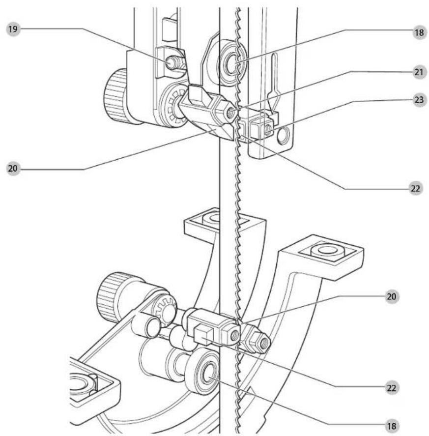
Fig. B
18 Rear blade support bearing
19 Locking grub screw for 18
20 Blade guide blocks 45°
21 Locking grub screw for 20
22 Blade guide blocks 90°
23 Locking grub screw for 22
Optional accessories (Fig. C1)
24 Legstand
Fig. C2
25 Mitre fence
26 Cut length gauge
Intended Use
Your DW738 / DW739 band-saw has been designed for professional workshop application: It performs straight, contour, mitre and bevel cuts on a wide range of materials such as wood, plastics, ferrous and non-ferrous metals and leather.
The nominal band length is 2095 mm and a width between 3 and 16 mm.

NING: Do not use the machine for other purposes as described.
DO NOT use under wet conditions or in the presence of flammable liquids or gases. These bandsaws are professional power tools.
DO NOT let children come into contact with the tool. Supervision is required when inexperienced operators use this tool.
- Young children and the infirm. This appliance is not intended for use by young children or infirm persons without supervision.
- This product is not intended for use by persons (including children) suffering from diminished physical, sensory or mental abilities; lack of experience, knowledge or skills unless they are supervised by a person responsible for their safety. Children should never be left alone with this product.
ASSEMBLY AND ADJUSTMENTS
WARNING: To reduce the risk of serious personal injury, turn tool off and connect tool from power source before making any adjustments or removing/installing attachments or accessories. Be sure the trigger switch is in the OFF position. An accidental start-up can cause injury.
The machine is fully assembled except for the table and rip fence.
Installing the Machine (Fig. A)
To ensure safe operation, the machine has always to be mounted to the workbench or to the ground. Use diameter 8 mm bolts with 100 mm length.
- Mark the position of the four mounting holes 16 provided in the base of the machine on the workbench.
- Place the machine on the workbench and insert the proposed bolts through the mounting holes into the workbench.
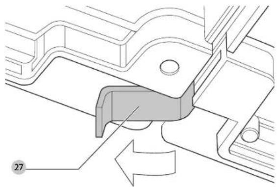
Mounting the Table (Fig. A, D1–D6)
- Turn the table tilt locking lever (9 in Fig. A) counterclockwise approximately half a turn to release the tilt segments (28 in Fig. D2).
- Swing back the connecting plate 27 which covers the blade slot in the table (Fig. D1).
- Place the table onto the segments 28 with the blade slot pointing to the front of the machine (Fig. D2).
-
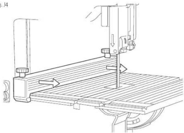
Carefully guide the table along the saw blade and align the holes in the table with those in the segments.
-
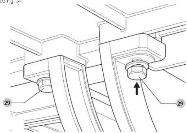
Insert one hex bolt M8 x 20 29 with washer into the two front holes and fasten them hand-tight (Fig. D3).
- Tilt the table to a 45° angle.
- Insert one hex bolt M8 x 20 29 with washer into the two rear holes (Fig. D4).
- Tighten all four bolts using the box spanner.
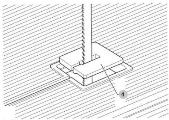
- Press the table insert 4 into place (Fig. D5).
- Swing the connecting plate 27 back into place (Fig. D1).
- Completely raise the blade guard 3 by turning the height adjuster 11 clockwise (Fig. A).
- Use a set square to check that the table is at a right angle to the saw blade when in the horizontal position. If adjustment is needed, loosen the table tilt locking lever and adjust the grub screw 30 as required (Fig. D6).
Mounting the Bandsaw Blade (Fig. A, B, D1, D5, E1–E4)

ING: The teeth of a new blade are very sharp and can be dangerous.
- Unscrew the two cover retention bolts 8 with box spanner to open the hinged door (Fig. A).
- Swing back the connecting plate 27 which covers the blade slot in the table (Fig. D1).
- Remove the table insert 4.
- Guide the blade through the blade slot in the table. Make sure that the teeth point to the front of the machine and downwards in the working area (Fig. E2)
- Carefully insert the blade into the blade guard slot 31 while turning it for 90^ (Fig. E3 & E4).
- Position the blade between the guide blocks 20 and 22.
- Move the blade around the band wheels 32 and 33 (Fig. E2) If necessary, lower the upper band wheel by turning the blade tension adjuster 6 (Fig. E2) counterclockwise.
- Mount the table insert 4 (Fig. D5).
- Swing the connecting plate 27 back into place (Fig. D1).
- Adjust the blade tension, the guide blocks and the support bearings as described below.

ING: Be aware the bandsaw blade shall be replaced in the described way only. Do it other bandsaw blade dimensions as specified under Technical Data.
Adjusting the Blade Tension (Fig. F1)
The correct tension depends on the width of the blade used. Refer to the table on the machine.
Adjust the blade tension using the blade tension adjuster 6 until the scale indicates the tension corresponding to the blade width.
Adjusting the Blade Position (Fig. A, F2, F3)
The blade must be centred on the rim of the band wheels.
- Open the hinged cover as described above.
- While rotating the upper band wheel with one hand, slightly rotate the blade centring adjuster 7 with the other (Fig. A, F3).

ING: Do not touch the blade but rotate the upper band wheel with your finger on the spokes.
Adjusting the Blade Guide Blocks and Rear Support Bearings (Fig. B, G1–G3)
During the sawing operation, the blade is exposed to frontal and lateral forces. The rear support bearings 18 are positioned 0.5 mm behind the blade to control the blade front-to-back movement. The 45° and 90° guide blocks are positioned 0.1 mm from the blade to control the lateral blade position.
- Remove the table insert and tilt the table to 45^ .
- Slacken the grub screws 19 and position the rear support bearings 18 away from the blade (Fig. G1).
- Adjust the knurled knob 34 to position the blade guide blocks just behind the blade teeth (Fig. G1).
- Position the rear support bearings 18:0.5 mm behind the blade and tighten the grub screws 19 (Fig. G1).
- Slacken the grub screws 21 and 23 and insert the blade guide blocks 20 and 22 in the holders (Fig. G1).
- Set the guide blocks to a distance of approx. 0.1 mm from the blade.
- Tighten the grub screws 21 and 23 (Fig. G1).
Changing Speed
DW738 (Fig. H1–H3)
Your DW738 bandsaw has two speeds. The low speed is obtained with the drive belt on the small drive pulley 35 (Fig. H2). The high speed is obtained with the drive belt on the large drive pulley 36 (Fig. H2). For speed rates, refer to the technical data.
- Slacken the motor location bolt 13 and move the motor to relax the drive belt (Fig. H1).
- Ease the drive belt from the wheel pulley and subsequently from the drive pulley 35 or 36 (Fig. H2, H3).
- Reinstall the drive belt on the wheel pulley and the required drive pulley 35 or 36.
- Reposition the motor to obtain the correct drive belt tension and secure the motor location bolt 13 (Fig. H1).
DW739 (Fig. A, I)
The speed of your DW739 bandsaw is infinitely variable over a wide range (refer to the technical data).
With the motor running, turn the blade speed adjuster 14 to obtain the desired speed (Fig. I).

VING: Do not force the speed adjuster beyond its range.
Mounting and Adjusting the Rip Fence (Fig. A, J1–J5)
- Mount a fence clamp piece (38 in Fig. J1) on each end of the fence (10 in Fig. A) using the M6 x 65 bolts (37 in Fig. J1) as shown (Fig. J1, J2).
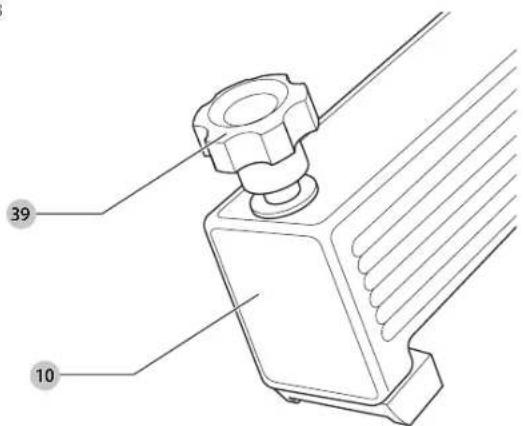
- Put a D6 washer on each of the bolts and screw the plastic knobs 39 onto the bolts (Fig. J3).
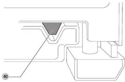
- Slide the fence onto the table as shown (Fig. J4). Make sure that the V-shaped lug 40 engages in the groove in the table (Fig. J5).
- To set the fence, slacken the knobs 39 and slide the fence into the desired position using the scale on the table (Fig. J3).
- Secure the fence in position by first tightening the front knob, then the rear knob. This ensures that the fence is aligned with the blade.
Range of Bandsaw Blade Available (Recommended Blades)
(overall length 2095 mm)
Type of blade Pitch (40) Width (40) Usage
| DT8480QZ 4.2 3.0 Wood – Fretsaw blade |
| DT8481QZ 4.2 12.0 Wood – General purpose |
| DT8482QZ 6.4 16.0 Wood – Thick cuts |
| DT8483QZ 3.2 6.0 Wood – Contour cuts |
| DT8484QZ 1.8 6.0 Metal – Non-ferrous – thin material |
| DT8485QZ 3.2 12 Metal – Non-ferrous – thick material |
| DT8486ZQ 3.2 10.0 Wood - Formica and laminates |
OPERATION
WARNING: To reduce the risk of serious personal injury, turn tool off and connect tool from power source before making any adjustments or removing/installing attachments or accessories. Be sure the trigger switch is in the OFF position. An accidental start-up can cause injury.
Instructions for Use
WARNING: Always observe the safety instructions and applicable regulations. Do not force the cutting action. Allow the motor to reach full speed before cutting.
- Select an appropriate saw blade.
- Never run the machine without the guards in place.
• Do not overtension the blade.
The attention of UK users is drawn to the "woodworking machines regulations 1974" and any subsequent amendments.
Ensure the machine is placed to satisfy your ergonomic conditions in terms of table height and stability. The machine site shall be chosen so that the operator has a good overview and enough free surrounding space around the machine that allows handling of the workpiece without any restrictions.
To reduce effects of vibration make sure the environment temperature is not too cold, machine and accessory is well maintained and the workpiece size is suitable for this machine. Turn the knob 11 in order to properly adjust the height of the blade guard.
Switching On and Off (Fig. E1)
For reasons of security, the On/Off switch 1 works only with the safety key 2 inserted. It also offers a no-volt release function: should the power be shut off for some reason, the switch has to be deliberately reactivated.
To operate
• I = ON
The tool now works in continuous operation.
- 0 = OFF
For safety reason the hinged cover is equipped with electrical interlock switch. Please close and lock the cover carefully then otherwise the machine will not run.
Basic Saw Cuts
Always position the blade guard approximately 10 mm above the surface of the workpiece.
Ripping (Fig. K)
- Install the rip fence as described above.
- Set the rip fence for the width of cut required by using the scale.
- Slowly feed the workpiece into the blade, keeping it firmly pressed onto the table and against the fence. Allow the teeth to cut and do not force the workpiece through the blade. The blade speed should be kept constant.

ING: Always use a push stick. Always switch off the tool when work is finished and unplugging.
Bevel cuts (Fig. L)
-
Set the table to the required angle.
-
When performing bevel cuts ensure that the rip fence is fixed on the lower side of the table.
- Proceed as for ripping.
Freehand cuts
Freehand cuts are performed without the help of a fence.

empt to cut curves smaller than the blade will allow.
- Whenever possible, connect a dust extraction device designed in accordance with the relevant regulations regarding dust emission.
MAINTENANCE
Your DrWALT power tool has been designed to operate over a long period of time with a minimum of maintenance. Continuous satisfactory operation depends upon proper tool care and regular cleaning.
WARNING: To reduce the risk of serious personal injury, turn tool off and disconnect tool from power source before making any adjustments or removing/installing attachments or accessories. Be sure the trigger switch is in the OFF position. An accidental start-up can cause injury.
WARNING: if the sow blade is worn replace it with a new or re-sharpened blade.

Lubrication
Your power tool requires no additional lubrication.

Cleaning
WARNING: Blow dirt and dust out of the main housing with dry air as often as dirt is seen during in and around the air vents. Wear approved eye protection and approved dust mask when performing this procedure.
WARNING: Never use solvents or other harsh chemicals for cleaning the non-metallic parts of the tool. These chemicals may weaken the materials used in these parts. Use a cloth dampened only with water and mild soap. Never let any liquid get inside the tool; never immerse any part of the tool into a liquid.

ING: To reduce the risk of injury, regularly clean the table top.

ING: To reduce the risk of injury, regularly clean the dust collection system.
WARNING: To reduce the risk of personal injury, turn unit off and disconnect machine from power source before cleaning. An accidental start-up can cause injury.
Before use, carefully check the adjustable upper and lower blade blocks, movable door as well as the dust extraction tube to determine that it will operate properly. Ensure that chips, dust or workpiece particle cannot lead to blockage of one of the functions.
In case of workpiece fragments jammed between bandsaw blade and lower blade block disconnect the machine from the power supply and follow the instructions given in section
Mounting the Bandsaw Blade. Remove the jammed parts and reassemble the saw blade. Keep the motor ventilation slots clear and regularly clean the housing with a soft cloth.

Dust Extraction
WARNING: Whenever possible, connect a dust extraction device designed in accordance with relevant regulations regarding dust emission.
Connect a dust extraction device designed in accordance with relevant regulation. The air velocity of external connected system shall be 20m/s +/- 2m/s. Velocity to be measured in the connection tube at the point of connection, with the tool connected but not running.
Transporting
Prior to transporting always disconnect the machine from the power source. Transport the machine at the carrying points. Always transport the machine with the guard fully down close to the table. Never carry the machine by the guard.
Optional Accessories
WARNING: Since accessories, other than those offered by DeWALT, have not been tested with this product, use of such accessories with this tool could be hazardous. To reduce the risk of injury, only DeWALT recommended accessories should be used with this product.
Consult your dealer for further information on the appropriate accessories.
Protecting the Environment

Separate collection. Products and batteries marked with this symbol must not be disposed of with normal household waste.
Products and batteries contain materials that can be recovered or recycled reducing the demand for raw materials. Please recycle electrical products and batteries
according to local provisions. Further information is available at www.2helpU.com.
SIERRA DE BANDA
DW738, DW739
¡Enhorabuena!
(Isolation double) – outils
Description (Fig. A–C)
Vice-President Engineering, PTE-Europa
DLWALT, Richard-Slinger-Strase 11,