
HBD5A - Beer dispenser HISENSE - Free user manual and instructions
Find the device manual for free HBD5A HISENSE in PDF.

| Product type | Beer dispenser / home beer cooler |
| Brand | Hisense |
| Model | HBD5A |
| Keg capacity | 5 liters (compatible with Heineken and universal kegs) |
| Temperature range | 3 to 12 °C (adjustable) |
| Power supply | 220-240 V ~ 50/60 Hz |
| Approx. dimensions (L x D x H) | 35 x 40 x 45 cm |
| Net weight approx. | 8.5 kg |
| Gas type | 16g CO2 cartridge (3 included) |
| Main functions | Digital temperature control, power-off memory, draft beer dispensing |
| Display | LED |
| Drip tray | Yes, removable |
| Tap handle | Yes, included and removable |
| Included accessories | Drip tray, handle, Heineken adapter, dispensing unit, 3 CO2 cartridges, cleaning kit, seals and tubes |
| Maintenance | Exterior cleaning with dry cloth; tap cleaning with provided hot water kit |
| Safety | Do not immerse, ventilation space 10 cm on each side, do not expose to rain or direct sunlight |
| Spare parts available | CO2 cartridges, seals, tubes, adapters, connectors |
| Repairability | Possible replacement of tubes, seals and cartridges by the user |
| Intended use | Domestic |
| General information | Manual available in 208 pages in French, brand Hisense, model HBD5A |
Frequently Asked Questions - HBD5A HISENSE
User questions about HBD5A HISENSE
0 question about this device. Answer the ones you know or ask your own.
Ask a new question about this device
Download the instructions for your Beer dispenser in PDF format for free! Find your manual HBD5A - HISENSE and take your electronic device back in hand. On this page are published all the documents necessary for the use of your device. HBD5A by HISENSE.
USER MANUAL HBD5A HISENSE
natural_image
Modern black and white water dispenser with a black handle and metallic lever (no text or symbols visible)HBD5A
SI Navodila za uporabo ....2
HR, BIH Upute za uporabu ....12
SRB - MNE Uputstva za upotrebu .....22
GB Instruction manual ....44
RO Manual de instructiuni 54
Namestitev
natural_image
Technical line drawing of a portable device with internal components and a separate view showing its exterior panel (no text or symbols present)natural_image
Technical line drawings of mechanical components including a tool, a bracket, and a cylindrical container (no text or symbols)
-
Zaprite zgornji pokrov hladilnika za pivo.
-
Za vklop hladilnika za pivo obrnite stikalo za vklop v položaj "I". (Položaj "0" pomeni izklop).
natural_image
Line drawing of a portable electrical plug with a power outlet, no text or symbols presentnatural_image
Technical line drawing of a three-blade propeller or fan assembly (no text or symbols)natural_image
Technical line drawing of a mechanical assembly with no visible text or symbolsnatural_image
Line drawing of a portable water dispenser with handle and vent, showing internal components and base (no text or symbols)Postavljanje
- Izvadite hladnjak za pivo iz ambalaže. Postavite ga na stabilnu, vodoravnu površinu i pobrinite se da bude udaljen najmanje 10 cm od drugih uređaja ili zida sa svake strane, kako bi se omogućilo pravilno prozračivanje uređaja i osigurala bolja učinkovitost.
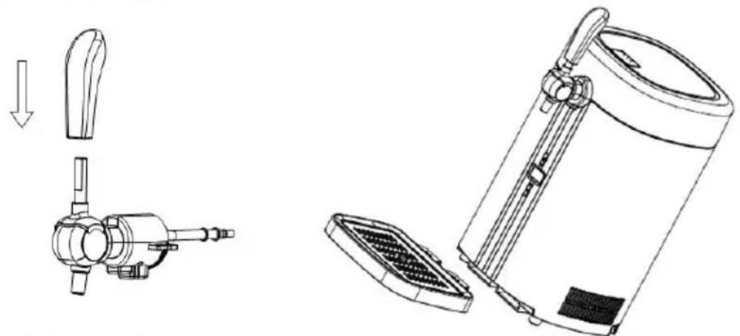
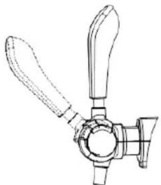
- Postavite ručku slavine tako da je spojite na slavinu, pazeći da se oba kraja savršeno uklapaju.
- Podignite glavni uređaj unatrag pod kutom 10 – 15°. Poravnajte posudu za skupljanje tekućine s utorom na dnu glavnog uređaja, umetnite i sastavite posudu za skupljanje tekućine, a zatim stavite proizvod ravno na radnu ploču.
natural_image
Technical line drawing of a portable device with ports and internal components, showing exploded and assembled views (no text or symbols)- Uključite hladnjak za pivo.
Napomena: nemojte spajati ili odspajati utikač dok su vam ruke mokre. Prije uporabe uvjerite se da je napon u skladu s oznakom na utikaču i provjerite je li kabel napajanja dobro spojen; ako nije, suzdržite se od uporabe i nazovite servisni centar.
Heineken bačva
Heineken bačve prethodno su napunjene CO2 i ne zahtijevaju uporabu regulatora. Nema potrebe za ugradnjom jedinice za CO2.
natural_image
Technical line drawings of mechanical components including a tool, a bracket, and a cylindrical container (no text or symbols)
natural_image
Line drawing of a portable electronic device with a power outlet and cable (no text or symbols)- Trebat će 19 – 24 sata da se pivo ohladi na 3 – 6°C pri temperaturi okoline od 22 - 24°C. Ta će se temperatura zatim održavati. Međutim, predlažemo da u početku hladite bačvu piva najmanje 12 sati u hladnjaku prije nego što je stavite u hladnjak za pivo, posebno kada je temperatura okoline viša od 25°C.
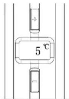
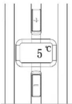
- Funkcija regulacije temperature: temperatura pokretanja ista je kao i prethodna podešena temperatura. Temperatura hlađenja može se podesiti pritiskom na tipke „+“ ili „-“ na upravljačkoj ploči. Temperatura se povećava za jedan stupanj svakim pritiskom tipke „+“. Pritisnite tipku „-“ jednom za snižavanje temperature za jedan stupanj. Na zaslonu će se prikazati trenutačna temperatura piva u bačvi. Pritisnite bilo koju tipku za prikaz podešene temperature; ona će se vratiti na trenutačnu temperaturu nakon 3 sekunde. Temperatura hlađenja hladnjaka za pivo može se podesiti između 3 i 12 °C. Uređaj ima funkciju memorije za isključivanje (tvornička postavka je 5 °C).
natural_image
Technical line drawing of a three-blade propeller or fan assembly (no text or symbols)natural_image
Technical line drawings of mechanical components inside a cylindrical housing, showing internal assembly and mounting features (no text or symbols)natural_image
Technical line drawing of a mechanical device with open lid and three views showing internal components (no text or symbols)- Slijedeći prethodne korake, možete početi upotrebljavati funkciju piva.
Zamjena bačve piva
- Kada nestane piva u bačvi, prije nego što se prebacite na novu bačvu piva, otvorite slavinu i pustite višak plina iz bačve (to može biti popraćeno pivskom pjenom).
- Izvadite priključak iz bačve.
- Preporučuje se čišćenje mehanizma za slavinu svaki put kada mijenjate bačvu piva. Pogledajte sadržaj u nastavku koji se odnosi na čišćenje.
Za univerzalnu bačvu od 5 l
- Otvorite gornji poklopac stroja, zatim otvorite slavinu i pustite višak plina iz mlaznice (može se ispustiti i pjena).
- Odspojite priključak za slavinu s jedinice za točenje piva i najprije pritisnite bijeli gumb dok ga vadite.
- Zatim izvadite jedinicu za točenje piva i bačvu piva iz uređaja.
- Izvadite jedinicu za točenje piva iz prazne bačve piva.
- Uzmite novu bačvu piva, ponovno pričvrstite jedinicu za točenje piva i stavite je u uređaj.

natural_image
Technical line drawing of a mechanical assembly with internal components and a cylindrical tank (no text or symbols)natural_image
Line drawing of a portable water dispenser with open lid and side panel (no text or symbols)Montaža
- Izvadite frižider za pivo iz pakovanja. Postavite ga na stabilnu, horizontalnu površinu i uverite se da je udaljen najmanje 10 cm od drugih uređaja ili zida sa svake strane, kako bi se omogućilo pravilno provetravanje uređaja i obezbedile bolje performanse.
- Postavite ručku slavine tako što ćete je spojiti sa slavinom, vodeći računa da se oba kraja potpuno uklapaju.
- Podignite glavni uređaj unazad pod uglom od 10-15°. Poravnajte tacnu za sakupljanje tečnosti sa otvorom na dnu glavnog uređaja, umetnite i stavite tacnu za sakupljanje tečnosti, a zatim postavite proizvod ravno na radnu površinu.

natural_image
Technical line drawing of a portable air purifier device with exploded view and side view (no text or symbols)- Uključite frižider za pivo.
Napomena: Nemojte uključivati ili isključivati utikač dok su vam ruke mokre. Pre upotrebe, uverite se da je napon u skladu sa oznakom na utikaču i proverite da li je kabl za napajanje dobro povezan; ako nije, nemojte da koristite uređaj, pozovite servisni centar.
Heineken bure
Heineken burad su prethodno napunjena sa CO2 i ne zahtevaju upotrebu regulatora. Nema potrebe za ugradnjom jedinice za CO2.
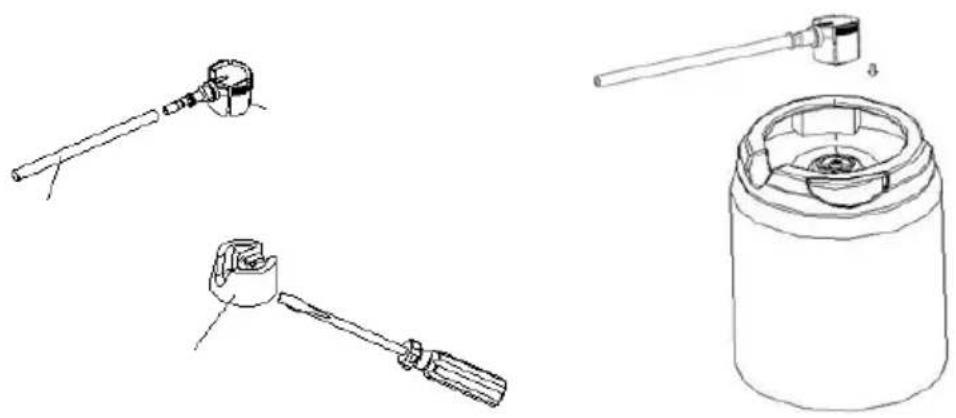
- Heineken konektor koji dolazi sa vašim frižiderom za pivo može da radi sa svim Heineken buradima od 5 litara. Međutim, uz pomoć šrafcigera sa ravnom glavom koji se isporučuje sa frižiderom za pivo morate da uklonite zelenu bazu iz bureta i instaliralate novi konektor.
- Instalirajte adapter frižidera za pivo na način opisan na buretu.
natural_image
Technical line drawings of mechanical components including a tool, a bracket, and a cylindrical container (no text or symbols)
-
Zatvorite gornji poklopac frižidera za pivo.
-
Okrenite prekidač za napajanje u položaj „l“ da biste uključili frižider za pivo. (Položaj "0" - isključeno).
NAPOMENA: Da biste izbegli strujni udar, proverite da li su vam ruke suve kada rukujete frižiderom za pivo.
natural_image
Line drawing of a portable electrical outlet with a plug and power connector (no text or symbols)-
Biće potrebno 19-24 sati da se pivo ohladi na 3-6 °C na temperaturi okoline 22-24°C. Ova temperatura će se zatim održavati. Međutim, predlažemo da u početku ohladite bure piva najmanje 12 sati u frižideru pre nego što ga stavite u frižider za pivo, posebno kada je temperatura okoline viša od 25°C.
-
Funkcija regulacije temperature: temperatura pokretanja je ista kao i prethodna podešena temperatura. Temperatura hlađenja se može podesiti pritiskom na tastere "+" ili "-" na kontrolnoj tabli. Temperatura se povećava za jedan stepen svaki put kad pritisnete taster "+" Pritisnite taster "-" jednom da biste snizili temperaturu za jedan stepen. Na ekranu će se prikazati trenutna temperatura piva u buretu. Pritisnite bilo koje dugme da biste videli podešenu temperaturu; posle 3 sekunde vratiće se na trenutnu temperaturu. Temperatura hlađenja frižidera za pivo može se podesiti između 3 i 12 °C. Mašina ima funkciju memorije tokom isključivanja (fabrička postavka je 5 °C).
- Sipajte pivo povlačenjem mehanizma slavine.
Napomena: Operite čašu pre upotrebe; ako je pivska čaša/krigla previsoka ili ako pivo nije dovoljno hladno, to će rezultirati velikom količinom pene prilikom sipanja.
natural_image
Line drawing of a three-blade propeller or fan assembly (no text or symbols)natural_image
Technical line drawing of a mechanical device with a downward arrow indicating motion (no text or symbols present)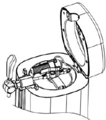
natural_image
Technical line drawing of a mechanical device with open lid and internal components (no text or symbols)- Okrenite sklop ventila za smanjenje pritiska od dna do vrha pod odgovarajućim uglom, sa maksimalnim uglom ne većim od 90 stepeni. Zatim odvrnite čauru patrone, postavite patronu od 16 g Co2 (sa pričvršćene 3 Co2 patrone) u čauru patrone i pažljivo i brzo zavrnite patronu uloška (u smeru kazaljke na satu za zatezanje, u suprotnom smeru od kazaljke na satu za labavost) dok se ne čuje zvuk "klik", što ukazuje na to da je zaptivna masa patrone probušena i da Co2 plin može slobodno da teče. Zatim okrenite sklop ventila za smanjenje pritiska u prvobitni položaj i umetnite ga u jedinicu za točenje piva. Da biste zamenili plinsku patronu, sledite obrnute korake (uverite se da je plin u potpunosti iskorišćen prilikom zamene plinske patrone).
- Prateći prethodne korake, možete početi da koristite uređaj.
Zamena bureta piva
- Kada nestane piva u buretu, pre nego što predete na novo bure, otvorite slavinu i pustite višak plina iz bureta (ovo može biti praćeno pivskom penom).
- Izvadite konektor iz bureta.
- Preporučuje se čišćenje mehanizma za slavinu svaki put kada menjate bure. Pogledajte sadržaj u nastavku u vezi sa čišćenjem.
Za univerzalno 5l bure
- Otvorite gornji poklopac uređaja, zatim otvorite slavinu i pustite višak plina iz mlaznice (takođe može doći do ispuštanja pene).
- Odvojite priključak za slavinu od jedinice za točenje piva i prvo pritisnite belo dugme dok ga vadite.
- Zatim izvadite jedinicu za točenje piva i bure iz uređaja.
- Izvadite jedinicu za točenje piva iz praznog bureta piva.
- Uzmite novo bure piva, ponovo pričvrstite jedinicu za točenje piva i stavite ga u uređaj.

natural_image
Technical line drawing of a mechanical device with internal components and a cylindrical housing (no text or symbols)Prvo, izvadite desnu kukicu i gurnite levu kukicu ručke u smeru strelice. Zatim izvucite jedinicu za točenje piva iz bureta.
Zamena CO2 patrone
Ako pivo ne izlazi prilikom pritiskanja (posebno kada ste sigurni da ima piva u buretu), zamenite Co2 patronu.
natural_image
Line drawing of a portable water dispenser with lid and handle (no text or symbols)Монтажа
natural_image
Technical line drawing of a portable device with ports and internal components, showing exploded and assembled views (no text or symbols)natural_image
Technical line drawings of mechanical components including a tool, bracket, and cylindrical container (no text or symbols)
natural_image
Line drawing of a portable electrical plug with a power outlet, no text or symbols presentnatural_image
Technical line drawing of a three-blade propeller or fan assembly (no text or symbols)natural_image
Technical line drawing of a mechanical device with a downward arrow indicating motion (no text or symbols present)
natural_image
Technical line drawing of a mechanical device with open lid and internal components (no text or symbols)natural_image
Technical line drawing of a mechanical device with internal components and a cylindrical housing (no text or symbols)natural_image
Line drawing of a portable water dispenser with open lid and side panel (no text or symbols)This is a household beer cooler. It brings beer to the best temperature for cold storage (3 to 6°C) within 16-21 hours.
The beer cooler can keep a 5-litre keg cool for an almost indefinite period. We do, however, suggest that you initially cool your beer keg for at least 12 hours in your refrigerator before placing it into the beer cooler.
Important safety instructions
- Before use, check whether the power cord is well connected; if not, please refrain from use and call the service centre.
- If the power cord is damaged, it must be replaced by the manufacturer, its service agent or a similarly qualified person in order to avoid a hazard.
- Before use, check whether the plug conforms with the socket; if not, please refrain from use and call the service centre.
- Due to the electric current, do not connect or disconnect the plug if your hands are wet.
- Place the beer cooler on a dry, horizontal surface.
- To ensure the beer cooler is well ventilated, make sure the appliance has at least 5 inches / 10cm of space on either side.
- Never place the beer cooler under direct sunlight.
- Never cover the beer cooler with another object while it is in operation.
- The beer cooler must be installed in an area protected from the elements (i.e. wind, rain, water spray or dripping).
- Before proceeding with cleaning and maintenance, make sure the power supply of the unit is disconnected. Failure to do so can result in electric shock or death.
- Do not immerse the beer cooler or power plug in water or any other liquid.
- Do not use coarse cloths or any abrasive substances to clean the beer cooler.
- Do not take the beer keg out of the beer cooler if the beer is not completely used up.
- Do not take the Co2 cartridge out before the Co2 contents inside are used up.
- Do not use the Co2 cartridge if the room temperature is over 49^ C. Failure to adhere to this can result in explosion or death.
- Never allow children to operate, play with, or crawl inside the beer cooler.
- This appliance can be used by children aged 8 and above and persons with reduced physical, sensory or mental capabilities, or lack of experience and knowledge, if they are supervised or have been given instructions concerning safe use of the appliance, and on condition that they understand the hazards
involved. Children should not play with the appliance. Cleaning and user maintenance should not be carried out by children without supervision.
- Children should be supervised to ensure that they do not play with the appliance.
- Warning: Do not store explosive substances such as aerosol cans with a flammable propellant in this appliance.
- This appliance is intended for use in households and for similar applications.
This equipment is labelled in compliance with the European Directive 2012/19/EC on waste electric and electronic equipment – WEEE. The Directive specifies the requirements for collection and management of waste electric and electronic equipment effective in the entire European Union.
How to select the keg
- Use a sealed 5-litre Heineken keg or a universal 5-litre keg.
- Pay close attention to the safety and storage messages on and around the keg.
- Check that the keg is not damaged and that the beer is not out of date before purchasing.
- Protect the top surface from any damage, as this may result in difficulties properly installing the Heineken adaptor.
- Before next use, keep the keg in a cool place for at least 12 hours. Do not keep in a very cold place such as a refrigerator.
- Never shake the keg before use.
- Never place the beer keg under direct sunlight.
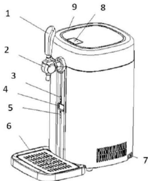
General description
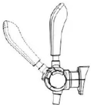
- Tap handle
- Tap
- Digital control button +
- LED display
-
Digital control button –
-
Drip tray
- AC power switch
- Door lock button
- Top cover
Installation
- Take the beer cooler out of its packaging. Place it on a steady, horizontal surface, and make sure it is at least 10 cm away from other appliances or the wall on each side, so as to allow correct ventilation of the appliance and ensure a better performance.
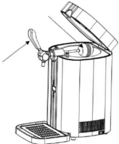
- Install the tap handle by connecting it to the tap, making sure both ends fit together perfectly.
- Lift the main machine backwards at an angle of 10-15°. Align the drip tray with the slot at the bottom of the main machine, insert and assemble the drip tray, and then place the product flat on the worktop.

natural_image
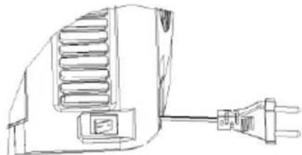
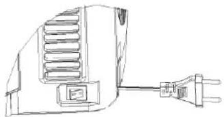
Technical line drawing of a portable device with ports and internal components, showing exploded and assembled views (no text or symbols)- Plug in the beer cooler.
Note: Do not connect or disconnect the plug while your hands are wet. Before use, make sure the voltage conforms with the mark on the plug, and check that the power cord is well connected; if not, please refrain from use and call the service centre.
Heineken Keg
Heineken kegs are pre-loaded with Co2, and do not require the use of a regulator. There is no need to install a Co2 unit.
- The Heineken connector that comes with your beer cooler can work with all Heineken 5-litre kegs. However you must use the flat headed screwdriver provided with the beer cooler to remove the green base from the keg and install the new connector.
- Install the adapter of the beer cooler according to the method on the keg description.
natural_image
Technical line drawings of mechanical components including a tool, bracket, and cylindrical container (no text or symbols)
- Close the top cover of the beer cooler.
- Turn the power switch to the "I" position to power on the beer cooler. (The position "0" is off). NOTE: To avoid electric shock, make sure your hands are dry when operating the beer cooler.
natural_image
Line drawing of a portable electrical plug with a power outlet, no text or symbols present- It will take 19-24 hours to cool the beer to 3 - 6^ C at an ambient temperature of 22 - 24^ C . This temperature will then be maintained. We do, however, suggest that you initially cool your beer keg for at least 12 hours in the refrigerator before placing it into the beer cooler, especially when the ambient temperature is higher than 25^ C .
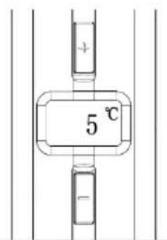
- Temperature-regulating function: the startup temperature is the same as the previous set temperature. The refrigeration temperature can be adjusted by pressing the "+" or "-" buttons on the control panel. The temperature increases by one degree each time you press the "+" button. Press the "-" button once to lower the temperature by one degree. The display will show the current temperature of the beer in the keg. Press any button to display the set temperature; it will return to the current temperature after 3 seconds. The refrigeration temperature of the beer cooler can be adjusted between 3 - 12^ C . The machine has a power-off memory function (factory setting is 5^ C ).
- Pour the beer by pulling down the tap mechanism.
Note: Clean your glass before use; if the beer or beer cup/glass is too high in temperature or if the beer is not cold enough, this will result in a lot of foam when pouring.
natural_image
Technical line drawing of a three-blade propeller or fan assembly (no text or symbols)- When tapping the beer, lean your beer glass against the pouring spout and slowly straighten it up as the beer rises. Then open the tap mechanism completely to avoid excess foam. It is advisable to pour a half-glass and then take a short pause before continuing with the rest.
Never immerse the pouring spout into the beer glass as this will result in excess foam. Remember to lock the tap after you finish pouring. - It is normal to have more bubbles when pouring the first 3 glasses of beer.
- There will be a sharp, high-speed jet when pouring the last glass of beer from the keg.
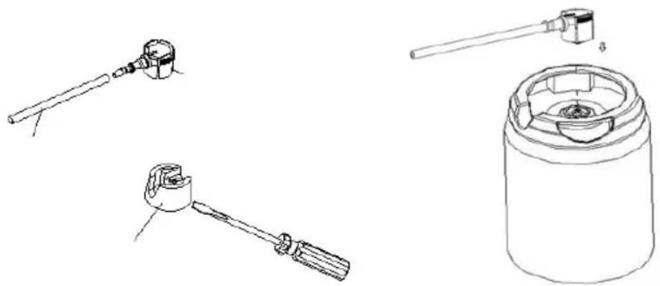
Universal 5L Keg
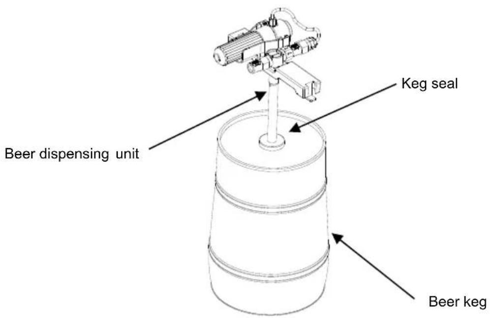
- Deflation step for discharging 400-500ml of beer from the beer keg, according to the deflation operation instructions on the beer keg body.
- Align the suction tube of the beer dispensing unit (pre-installed before delivery) vertically with the keg seal in the middle of the top of the keg (please check or replace the keg seal according to the sealing part of the previous keg). Press the beer dispensing unit with your hand so that the suction tube inserts the keg seal into the keg, and then quickly insert the suction tube into the keg completely. This indicates that the beer dispensing unit has been correctly fixed onto the keg.
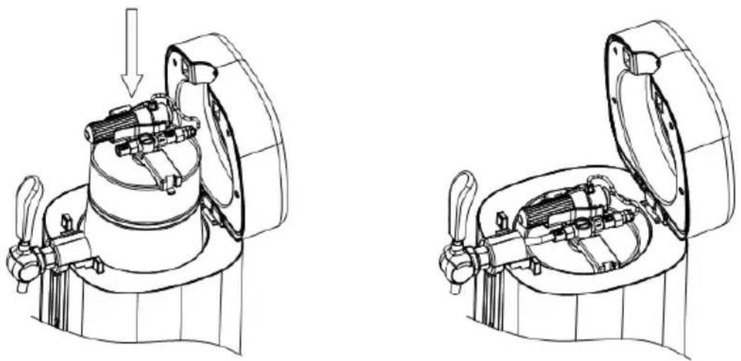
- Open the top cover of the machine by pressing the button on the top cover with a force of 60-80N. Put the keg, with the beer dispensing unit installed, into the cavity of the machine. Then connect the adaptor with the tap connector.
Note: Keep the tap closed when connecting the beer dispensing unit to the tap connector.
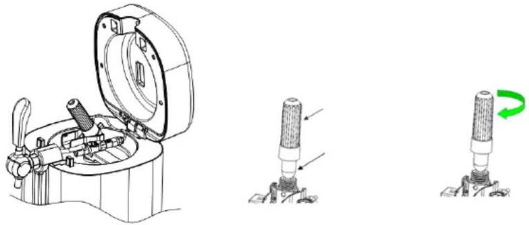
natural_image
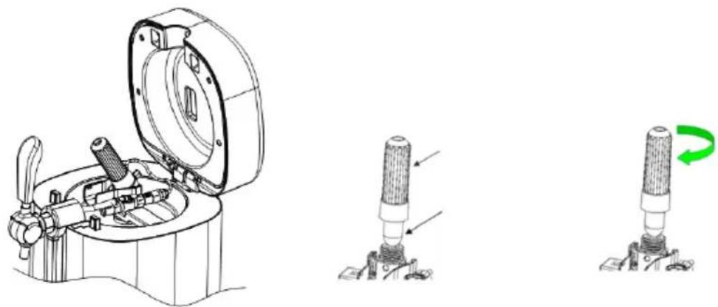
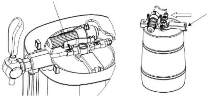
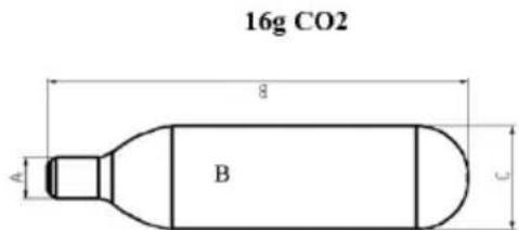
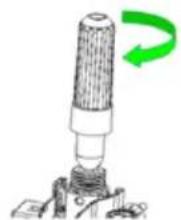
Technical line drawings of mechanical components inside a cylindrical housing, showing internal assembly and mounting features (no text or symbols)- Rotate the pressure reducing valve assembly from the bottom to the top at an appropriate angle, with a maximum angle of no more than 90 degrees. Then unscrew the cartridge sleeve, install a 16g Co2 cartridge (with 3 Co2 cartridges attached) into the cartridge sleeve, and carefully and quickly tighten the cartridge sleeve (clockwise for tightness, counterclockwise for looseness) until a "click" sound is heard, indicating that the cartridge sealant has been punctured and that Co2 gas can flow freely. Then turn the pressure reducing valve assembly to its original position and insert it into the beer dispensing unit. To replace the gas cartridge, follow the reverse steps (please ensure that the gas has been fully used up when replacing the gas cartridge).
natural_image
Technical line drawing of a mechanical device with open lid and three views showing internal components (no text or symbols)- Following the previous steps, you can start using the beer function.
Replacing the beer keg
- When the beer in the keg runs out, before changing to a new beer keg, open the tap and let the excess gas out of the keg (this may be accompanied by some beer foam).
- Take out the connector from the keg.
- It is recommended to clean the tap mechanism each time you change the beer keg. Please refer to the contents below regarding cleaning.
For the universal 5L keg
- Open the top cover of the machine, then open the tap and let the excess gas out of the nozzle (foam may also be emitted).
- Disconnect the tap connector from the beer dispensing unit, and press the white button first while taking it out.
- Then take out the beer dispensing unit and the beer keg from the machine.
- Remove the beer dispensing unit from the empty beer keg.
- Take a new keg of beer, reattach the beer dispensing unit and put it in the machine.
natural_image
Technical line drawing of a mechanical assembly with internal components and a cylindrical tank (no text or symbols)Firstly, take out the right end hook and push the left end hook of the handle to the side where the arrow is pointing. Then pull out the beer dispensing unit from the keg.
Replacing the Co2 cartridge
If there is no beer coming out when pressing (especially when you are sure there is beer in the keg), please replace the Co2 cartridge.
- Ensure that the tap of the machine is closed, open the top cover of the machine, unscrew the cartridge sleeve, and remove the empty Co2 cartridge from the cartridge sleeve. Insert a new Co2 cartridge into the cartridge sleeve, and then carefully and quickly tighten the cartridge sleeve (clockwise to tighten, counterclockwise to loosen) until a "click" sound is heard, indicating that the cartridge sealant has been punctured and that Co2 gas can flow freely. Then turn the pressure reducing valve assembly downwards and buckle it into the liquor outlet assembly.
- Close the top cover of the machine.
- Now you can prepare to use the tap to pour the beer.
Attention
- Please use the appropriate Co2 cartridge.
The below Co2 cartridge information is for your reference. To avoid explosion, never use nitrogen gas cartridges in the beer cooler, due to their much higher pressure. - New Co2 cartridges must be well maintained. To avoid a hazard, they should not be played with.
Cleaning the beer tap mechanism
The beer cooler must conform with hygiene standards, and should be cleaned before first use or after a long period without use. The whole machine should be cleaned with a dry cloth. Otherwise, two cleaning steps are recommend, as follows:
- Load warm water into the cleaning kit.
- Connect the end of the piercing pin, press the water into the pin to clean the pin tube, and push the water out from the beer tube at the other end. Repeat this until the beer tube is clean (at least 3 bottles of warm water are generally required). Clean the beer tap mechanism as shown below.
natural_image
Line drawing of a portable water dispenser with handle and vent, showing internal components and base (no text or symbols)Never put tap mechanism parts in the washing machine or dishwasher.
Never use a chemical cleaning detergent to clean the parts; warm or purified water is recommended.
Accessories and spare parts
| Name | Qty | Installation | Image | ||
| 1 | Connector sealing ring | 3 | Pressure reducing valve | 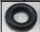 | |
| 2 | Cylinder connector | 2 | Pressure reducing valve | 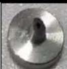 | |
| 3 | Beer outlet tube (short) | 2 | Beer outlet connector | 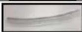 | |
| 4 | Beer outlet tube (long) | 2 | Beer outlet connector | 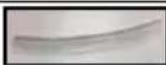 | |
| 5 | Suction tube sealing ring | 4 | Suction tube | 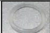 | |
| 6 | Keg seal | 2 | Standard keg |  | |
| 7 | Adaptor | 2 | Heineken keg |  | |
| 8 | Co2 cartridge | 3 | Pressure reducing valve assembly | 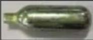 | |
| 9 | Cleaning bottle | 1 | Pressure reducing valve |  | |
How to change the beer tube
If the beer tube breaks, leading to a leakage, make sure to replace it immediately.
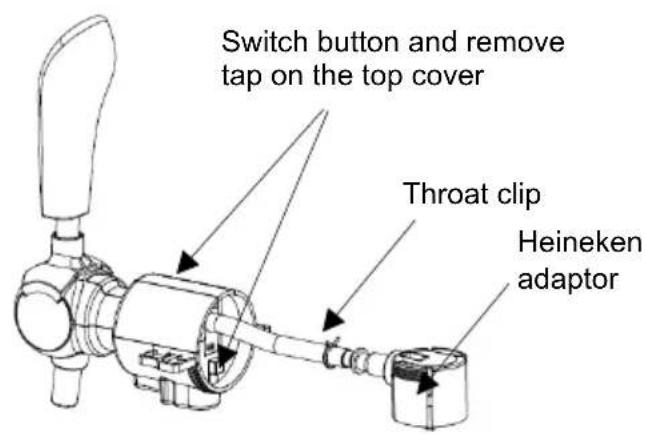
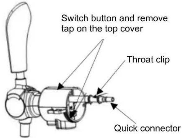
- Open the detachable tap cover, pull the tap handle in the direction of the beer, and pull out the beer tube.
- For a Heineken keg: remove the beer throat clip and pull out the Heineken adaptor.
- For a universal 5L keg: remove the beer throat clip and pull out the quick connector.
- Get a new beer tube and install it in reverse order.
Troubleshooting
| Problem | Possible cause | Solution |
| The tap does not work / beer is not coming out. | 1. The pouring tube is not properly connected.2. No keg, or no beer in the keg. | 1. Make sure the pouring tube is well connected.2. Change to a new keg. |
| Too much foam coming out | 1. The beer is not being poured correctly.2. The temperature of the beer is too high (best at 3-6°C).3. The keg was shaken before use.4. There is almost no beer left in the keg. | 1. Use the correct method to pour the beer.2. Cool the beer down to 3-6°C.3. Put the beer keg aside for a while until there is no foam remaining inside.4. Change to a new keg. |
| Beer flows out too slowly. | 1. Co2 pressure inside the keg isn't high enough.2. The connection tube or pouring tube is leaking. | 1. Change to a new keg.2. Check whether the tube is leaking; if so, replace the tube. |
ENVIRONMENT
At the end of the appliance's usable life, do not discard it with common household waste. Take it to an authorised recycling centre; this will help preserve the environment.
WARRANTY AND REPAIR
For more information or in case of problems, please contact the Hisense Call Centre in your country (phone number listed in the International Warranty Sheet). If there is no such centre in your country, please contact your local Hisense dealer or the Hisense small domestic appliance department. For personal use only!
Hisense
WISHES YOU A LOT OF PLEASURE IN USING YOUR APPLIANCE.
We reserve the right to modifications.
Introducere
Instalare
natural_image
Technical line drawing of a portable device with ports and internal components, showing exploded and assembled views (no text or symbols)natural_image
Technical line drawings of mechanical components including a tool, a bracket, and a cylindrical container (no text or symbols)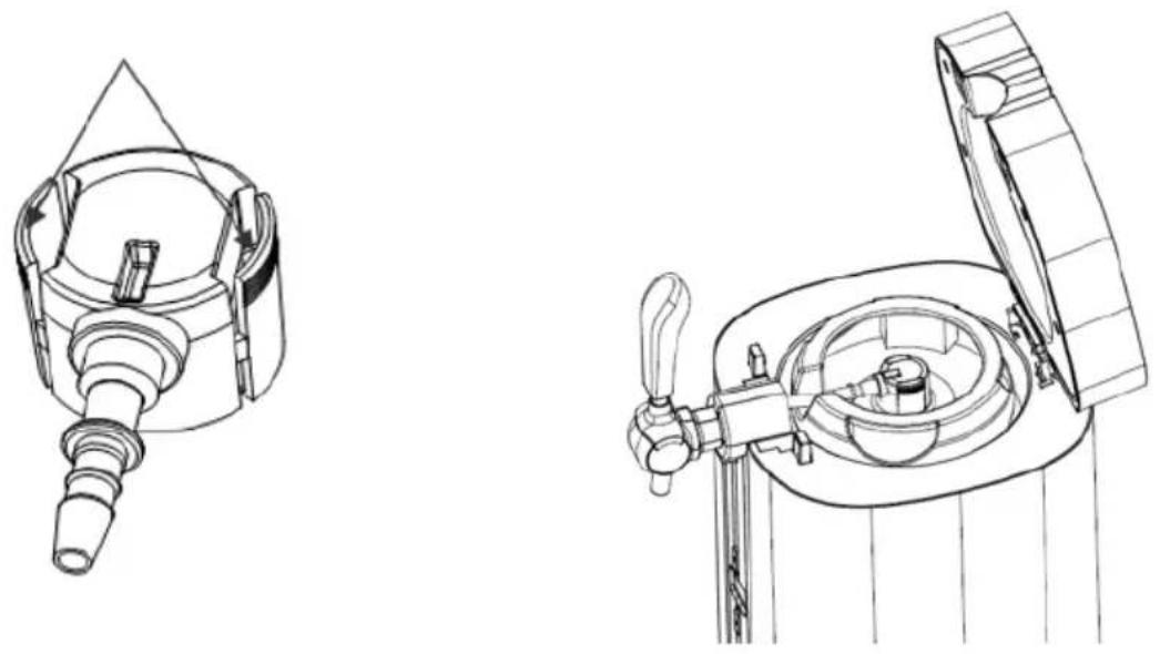
natural_image
Line drawing of a portable electrical plug with a power outlet, no text or symbols presentnatural_image
Technical line drawing of a three-blade propeller or fan assembly (no text or symbols)natural_image
Technical line drawings of mechanical components inside a cylindrical housing, showing internal assembly and mounting features (no text or symbols)natural_image
Technical line drawing of a mechanical device with open lid and three views showing internal components (no text or symbols)natural_image
Technical line drawing of a mechanical assembly with internal components and a cylindrical tank (no text or symbols)natural_image
Line drawing of a portable water dispenser with handle and vent, showing internal components and base (no text or symbols)Üzembe helyezés
natural_image
Technical line drawing of a portable device with ports and internal components, showing exploded and assembled views (no text or symbols)natural_image
Technical line drawings of mechanical components including a tool, a bracket, and a cylindrical container (no text or symbols)
natural_image
Line drawing of a portable electrical plug with a power outlet, no text or symbols presentnatural_image
Line drawing of a three-blade propeller or fan assembly (no text or symbols)natural_image
Technical line drawing of a mechanical device with a downward arrow indicating motion (no text or symbols present)
natural_image
Technical line drawing of a mechanical device inside a toilet (no text or symbols)natural_image
Technical line drawing of a mechanical assembly with internal components and a cylindrical housing (no text or symbols)natural_image
Line drawing of a portable water dispenser with handle and vent, showing internal components and airflow direction (no text or symbols)Инсталиране
natural_image
Technical line drawing of a portable device with ports and internal components, showing exploded and assembled views (no text or symbols)natural_image
Technical line drawings of mechanical components including a tool, bracket, and cylindrical container (no text or symbols)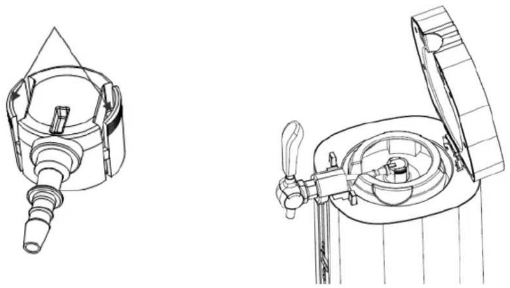
natural_image
Line drawing of a portable electronic device with a power outlet and plug (no text or symbols)natural_image
Line drawing of a three-blade propeller or fan assembly (no text or symbols)natural_image
Technical line drawing of a mechanical device with a downward arrow indicating motion (no text or symbols present)
natural_image
Technical line drawing of a mechanical device with open lid and internal components (no text or symbols)natural_image
Technical line drawing of a mechanical assembly with internal components and a cylindrical component (no text or symbols)natural_image
Line drawing of a portable water dispenser with open lid and side panel (no text or symbols)Установлення
natural_image
Technical line drawing of a portable device with ports and internal components, showing exploded and assembled views (no text or symbols)natural_image
Technical line drawings of mechanical components including a tool, a bracket, and a cylindrical container (no text or symbols)
natural_image
Line drawing of a portable electrical plug with a power outlet, no text or symbols presentnatural_image
Technical line drawing of a propeller or fan assembly (no text or symbols)natural_image
Technical line drawing of a mechanical device with a downward arrow indicating motion (no text or symbols present)
natural_image
Technical line drawing of a mechanical device inside a toilet (no text or symbols)natural_image
Technical line drawing of a mechanical assembly with internal components and a cylindrical housing (no text or symbols)natural_image
Line drawing of a portable water dispenser with handle and vent, showing internal components and base (no text or symbols)natural_image
Technical line drawing of a portable device with ports and internal components, showing exploded and assembled views (no text or symbols)natural_image
Technical line drawings of mechanical components including a tool, a bracket, and a cylindrical container (no text or symbols)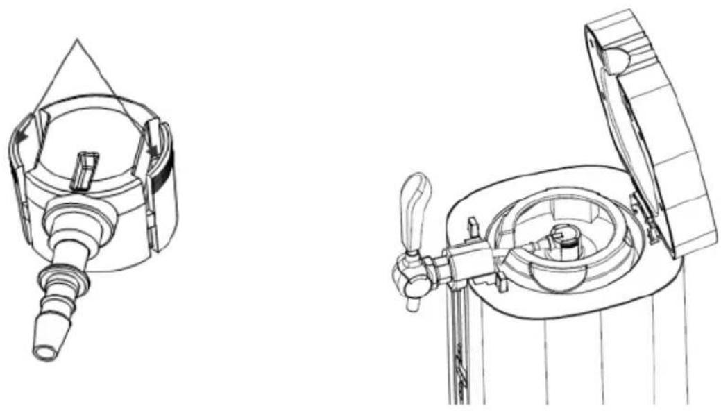
natural_image
Line drawing of a portable electronic device with a power outlet and plug (no text or symbols)natural_image
Line drawing of a three-blade propeller or fan assembly (no text or symbols)natural_image
Technical line drawings of mechanical components inside a cylindrical housing, showing internal assembly and mounting features (no text or symbols)natural_image
Technical line drawing of a mechanical device with open lid and three views showing internal components (no text or symbols)natural_image
Technical line drawing of a mechanical assembly with internal components and a cylindrical tank (no text or symbols)natural_image
Line drawing of a portable water dispenser with lid and handle (no text or symbols)Instalace
natural_image
Technical line drawing of a portable device with ports and internal components, showing exploded and assembled views (no text or symbols)natural_image
Technical line drawings of mechanical components including a tool, a bracket, and a cylindrical container (no text or symbols)
natural_image
Line drawing of a portable electronic device with a power outlet and internal circuit lines (no text or symbols)natural_image
Technical line drawing of a three-blade propeller or fan assembly (no text or symbols)natural_image
Technical line drawing of a mechanical device with a downward arrow indicating motion (no text or symbols present)
natural_image
Technical line drawing of a mechanical device with open lid and internal components (no text or symbols)natural_image
Technical line drawing of a mechanical device with open lid and internal components (no text or symbols)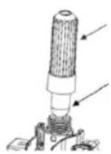
natural_image
Diagram of a mechanical component with a green curved arrow indicating rotation (no text or symbols)natural_image
Technical line drawing of a mechanical device with internal components and a separate cylindrical component (no text or symbols)natural_image
Line drawing of a portable water dispenser with lid and side panel (no text or symbols)INSTALACJA
natural_image
Technical line drawing of a portable air purifier device with exploded view and side view (no text or symbols)natural_image
Technical line drawings of mechanical components including a tool, a bracket, and a cylindrical container (no text or symbols)
natural_image
Line drawing of a portable electrical outlet with a plug and ventilation grille (no text or symbols)natural_image
Technical line drawing of a propeller or fan assembly (no text or symbols)natural_image
Technical line drawing of a mechanical device with a downward arrow indicating motion (no text or symbols present)
natural_image
Technical line drawing of a mechanical device inside a toilet (no text or symbols)natural_image
Technical line drawing of a mechanical device with internal components and a cylindrical component (no text or symbols)natural_image
Line drawing of a portable water dispenser with handle and vent, showing internal components and base (no text or symbols)Установка
natural_image
Technical line drawing of a portable device with ports and internal components, showing exploded and assembled views (no text or symbols)natural_image
Technical line drawings of mechanical components including a tool, bracket, and cylindrical housing (no text or symbols)natural_image
Line drawing of a portable electronic device with a power outlet and plug (no text or symbols)natural_image
Technical line drawing of a three-blade propeller or fan assembly (no text or symbols)natural_image
Technical line drawings of mechanical components inside a cylindrical housing, showing internal assembly and mounting features (no text or symbols)natural_image
Technical line drawing of a mechanical device with internal components and a cylindrical housing (no text or symbols)natural_image
Line drawing of a portable water dispenser with lid and handle (no text or symbols)Montimi
natural_image
Technical line drawing of a portable device with ports and internal components, showing exploded and assembled views (no text or symbols)natural_image
Technical line drawings of mechanical components including a tool, a bracket, and a cylindrical container (no text or symbols)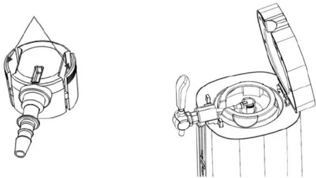
natural_image
Line drawing of a portable electrical plug with a power outlet (no text or symbols)natural_image
Line drawing of a three-blade propeller or fan assembly (no text or symbols)natural_image
Technical line drawing of a mechanical device with a downward arrow indicating motion (no text or symbols present)
natural_image
Technical line drawing of a mechanical device inside a toilet (no text or symbols)natural_image
Technical line drawing of a mechanical assembly with internal components and a cylindrical component (no text or symbols)natural_image
Line drawing of a portable water dispenser with handle and vent, showing internal structure without any text or symbolsInstallation
natural_image
Technical line drawing of a portable air purifier device with exploded and assembled views (no text or symbols)natural_image
Technical line drawings of mechanical components including a tool, a bracket, and a cylindrical container (no text or symbols)
natural_image
Line drawing of a portable electrical plug with a power outlet, no text or symbols presentnatural_image
Technical line drawing of a propeller or fan assembly (no text or symbols)natural_image
Technical line drawing of a mechanical device with a downward arrow indicating motion (no text or symbols present)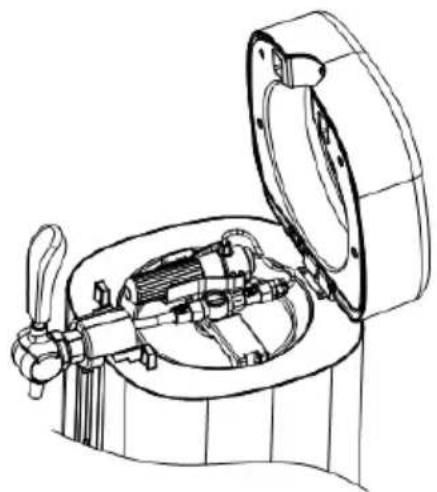
natural_image
Technical line drawing of a mechanical device with open lid and internal components (no text or symbols)natural_image
Technical line drawing of a mechanical assembly with internal components and a cylindrical component (no text or symbols)natural_image
Line drawing of a portable water dispenser with handle and vent, showing internal components and base (no text or symbols)Instalación
natural_image
Technical line drawing of a portable device with ports and internal components, showing exploded and assembled views (no text or symbols)natural_image
Technical line drawings of mechanical components including a tool, a bracket, and a cylindrical container (no text or symbols)
natural_image
Line drawing of a portable electrical plug with a power outlet (no text or symbols)natural_image
Technical line drawing of a three-blade propeller or fan assembly (no text or symbols)natural_image
Technical line drawings of mechanical components inside a cylindrical housing, showing internal assembly and mounting features (no text or symbols)natural_image
Technical line drawing of a mechanical assembly with internal components and a cylindrical housing (no text or symbols)natural_image
Line drawing of a portable water dispenser with handle and vent, showing internal components and base (no text or symbols)Instalação
natural_image
Technical line drawing of a portable device with internal components and a separate view showing its exterior panel (no text or symbols present)- Ligue o refrigerador de cerveja.
natural_image
Technical line drawings of mechanical components including a tool, a bracket, and a cylindrical container (no text or symbols)
natural_image
Line drawing of a portable electrical plug with a power outlet, no text or symbols presentnatural_image
Line drawing of a three-blade propeller or fan assembly (no text or symbols)natural_image
Technical line drawing of a mechanical device with a downward arrow indicating motion (no text or symbols present)
natural_image
Technical line drawing of a mechanical device with open lid and internal components (no text or symbols)natural_image
Technical line drawing of a mechanical device with internal components and a cylindrical housing (no text or symbols)natural_image
Line drawing of a portable water dispenser with open lid and side panel (no text or symbols)Installazione
natural_image
Technical line drawing of a portable device with ports and a lid, showing exploded and assembled views (no text or symbols)natural_image
Technical line drawings of mechanical components including a tool, a bracket, and a cylindrical container (no text or symbols)
natural_image
Line drawing of a portable electrical plug with a power outlet (no text or symbols)natural_image
Technical line drawing of a three-blade propeller or fan assembly (no text or symbols)natural_image
Technical line drawing of a mechanical device with a downward arrow indicating motion (no text or symbols present)
natural_image
Technical line drawing of a mechanical device with open lid and internal components (no text or symbols)natural_image
Technical line drawing of a mechanical device showing internal components and a cylindrical housing (no text or symbols)natural_image
Line drawing of a portable water dispenser with open lid and side panel (no text or symbols)Installation
natural_image
Technical line drawing of a portable air purifier device with exploded view and side view (no text or symbols)natural_image
Technical line drawings of mechanical components including a tool, bracket, and cylindrical housing (no text or symbols)
natural_image
Line drawing of a portable electrical plug with a power outlet, no text or symbols presentnatural_image
Technical line drawing of a three-blade propeller or fan assembly (no text or symbols)natural_image
Technical line drawing of a mechanical device with a downward arrow indicating motion (no text or symbols present)