
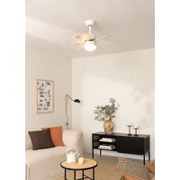
Wind Sail - Fan Create - Free user manual and instructions
Find the device manual for free Wind Sail Create in PDF.

| Product type | Ceiling fan |
| Brand | Create |
| Model | Wind Sail |
| Minimum installation height | 2.3 m |
| Downrod length | 15 cm or 25 cm |
| Power supply | 220-240 V ~ 50 Hz |
| Number of speeds | 3 speeds (estimated) |
| Remote control | Yes, wireless |
| Lighting | Optional, LED panel (if installed) |
| Blade material | Not specified |
| Weight | Not specified |
| Safety | Cut power at circuit breaker before installation; do not use a dimmer |
| Maintenance | Clean with a soft cloth; do not bend blades |
| Included accessories | Balancing kit, remote control, receiver |
| Warranty | Not specified |
Frequently Asked Questions - Wind Sail Create
User questions about Wind Sail Create
0 question about this device. Answer the ones you know or ask your own.
Ask a new question about this device
Download the instructions for your Fan in PDF format for free! Find your manual Wind Sail - Create and take your electronic device back in hand. On this page are published all the documents necessary for the use of your device. Wind Sail by Create.
USER MANUAL Wind Sail Create
Safety instructions 6
Parts list 7
Location and Installation requirements 8
Installation Instructions 9
Ceiling fan with led light 12
Ceiling fan without led light 13
Remote control 13
Troubleshooting 14
PORTUGUÊS
Thank you for choosing our ceiling fan. Before using the appliance, and to ensure the best use, carefully read these instructions.
The safety precautions enclosed herein reduce the risk of death, injury and electrical shock when correctly adhered to. Keep the manual in a safe place for future reference, along with the completed warranty card, purchase receipt and package. If applicable, pass these instructions on to the next owner of the appliance. Always follow basic safety precautions and accident-prevention measures when using an electrical appliance. We assume no liability for customer failing to comply with these requirements.
SAFETY INSTRUCTIONS
When using any electrical appliance, basic safety precautions should always be observed.
- Read this entire manual carefully before beginning installation. Save these instructions.
- To reduce the risk of personal injury, attach the fan directly to the support structure of the building according to these instructions, and use only the hardware supplied.
- To avoid possible electrical shock, before installing your fan, disconnect the power by turning off the circuit breakers to the outlet box and associated wall switch location. If you cannot lock the circuit breakers in the off position, securely fasten a prominent warning device, such as a tag, to the service panel.
- All wiring must be in accordance with national and local electrical codes and ANSI/NFPA 70. If you are unfamiliar with wiring, use a qualified electrician.
- Do not bend the blade attachment system when installing, balancing, or cleaning the fan.
- Never insert foreign objects between rotating fan blades.
- To reduce the risk of fire, electrical shock, or motor damage, do not use a solid-state speed control with this fan. Use only original speed controls.
- This appliance can be used by children aged from 8 years old and above and persons with reduced physical, sensory or mental capabilities or lack of experience and knowledge if they have been given supervision or instruction concerning use of the appliance in a safe way and understand the hazards involved.
- Children shall not play with the appliance.
- Cleaning and user maintenance shall not be made by children unless they are older than 8 and supervised. Close supervision is necessary when any appliance is used by or near children.
NOTE: The important safety precautions and instructions appearing in the manual are not meant to cover all possible conditions and situations that may occur. It must be understood that common sense and caution are necessary factors in the installation and operation of this fan.
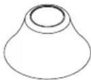
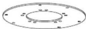
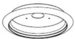
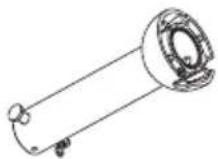
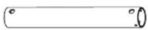
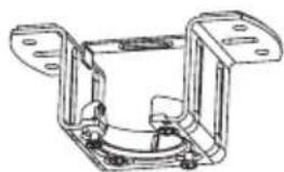
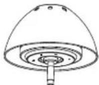
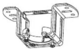
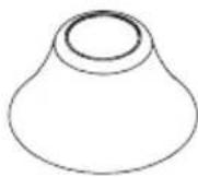
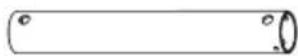
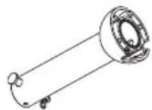
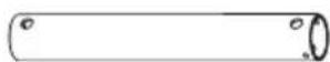
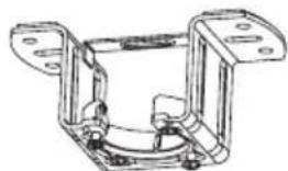
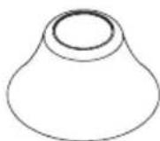
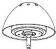
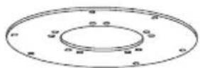
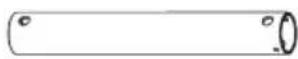
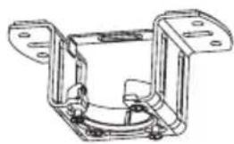
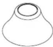
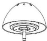
PARTS LIST
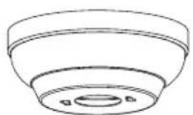
natural_image
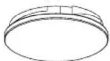
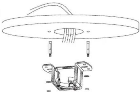
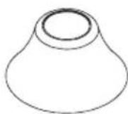
Simple line drawing of a bowl-shaped object with a central hole and two small dots, no text or symbols present.Ceiling Canopy
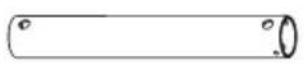
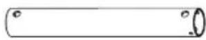
Downrod (x2 & hanger ball)
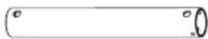
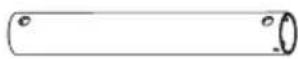
Downrod
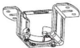
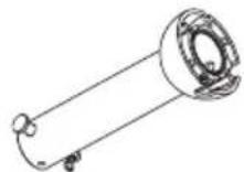
natural_image
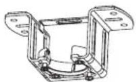
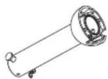
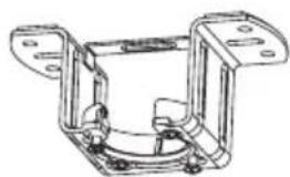
Technical line drawing of a mechanical bracket assembly (no text or symbols)Mounting Bracket
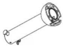
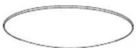
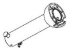
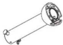
Motor decoration
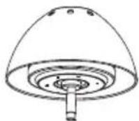
Motor housing
natural_image
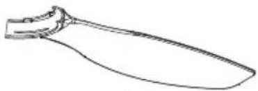
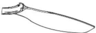
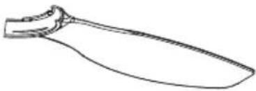
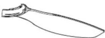
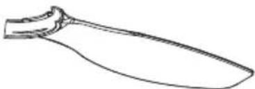
Line drawing of a knife handle (no text or symbols)3x Blades
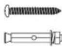
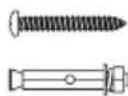
Expansion screws
Blade holder
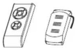
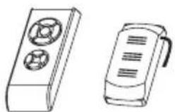
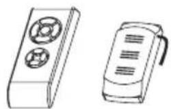
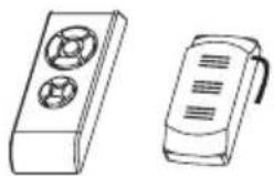
Remote control
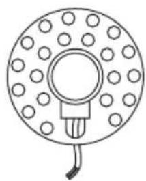
Option with light:

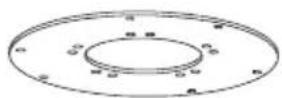
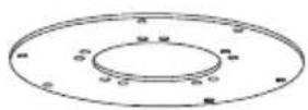
Lamp panel
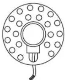
natural_image
Simple line drawing of a circular component with evenly spaced dots and a central hole, connected by a bulb (no text or symbols)LED panelLamp
Option without light:

Fixing screws
Decorative cover
Mechanical issues
- According to safety regulations, the lowest point of the fan blade must be at least 2.3m (7 feet) from the floor.
- Please, make sure the chosen location will not allow the rotating fan blades to come into contact with any objects.
- Ensure ceiling joists are sound and of adequate size and strength to support the weight of the fan.
- To reduce the risk of fire, electrical shock or personal injury, ensure that the fan mounting bracket is supported directly from the building structure. DO NOT mount to an outlet box.
- The mounting bracket must be firmly screwed to a load bearing structure, e.g. a concrete ceiling, steel structure or timber frame. If a timber frame is added, it must be securely nailed or screwed between two beams.
- To reduce risk of personal injury and property damage, do not bend or damage the downrod or the fan blades when handling or installing them. If you notice any product imperfections, please contact our after-sales service before proceeding to install the fan.
- Make sure the ceiling fan is securely fastened to the ceiling. All set screws must be checked and re-tightened where necessary before fan operation.
Electrical issues
- Always turn the power off before servicing the ceiling fan, turn off the circuit breaker that feeds the power to the light. To avoid possible electric shock, make sure electricity is turned off at the fuse box or circuit breaker panel before wiring.
- The fan, mounting bracket and light kit must be earthed. Ensure all spliced connections are adequately insulated.
Remote control connection
- Make the connection between the receiver cables and the fan motor cables following the color indications. Make sure the connection is tight.
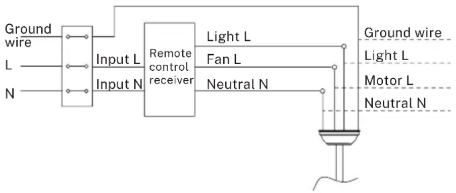
flowchart
graph LR
    A["Ground wire"] --> B["Input L"]
    C["L"] --> B
    D["N"] --> B
    B --> E["Input N"]
    E --> F["Remote control receiver"]
    F --> G["Light L"]
    F --> H["Fan L"]
    F --> I["Neutral N"]
    G --> J["Ground wire"]
    H --> J
    I --> J
    J --> K["Motor L"]
    J --> L["Neutral N"]
Hanging the fan
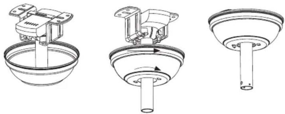
- Hang the fan on the ceiling mount. Bring the suspension axle closer to the bracket and let the motor assembly rest on the roof bracket. Insert the remote control receiver into the left space when installing the ceiling mount, between the ceiling and the suspension bar. So that the connection cables are outside the metal plate to connect the cables.
- Pass the receiver first, letting the cables protrude through the sides of the bracket, as indicated in the drawings.
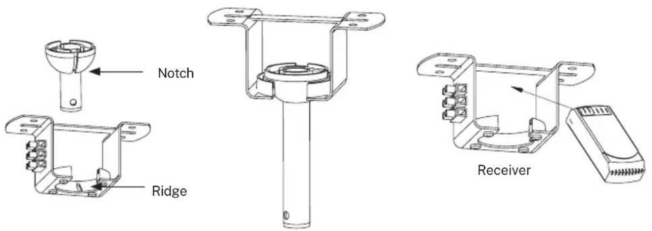
- Hang the motor housing on the mounting bracket. Rotate the fan so that the notch on the ball engages the ridge in the mounting bracket.
-
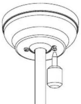
Place the remote control receiver in the slot on the mounting bracket as shown in the figure.
-
Check and confirm that all connections are proper and secure. When all the electrical connections are done, store all wires neatly.
- Do not attempt to control this fan from any wall or remote control that is not approved by the manufacturer for use with this fan. DO NOT use a solid state controller. The use of an unapproved wall or remote control will void the warranty.
- Do not connect the ceiling fan to a dimmer switch or a regulator.
INSTALLATION INSTRUCTIONS
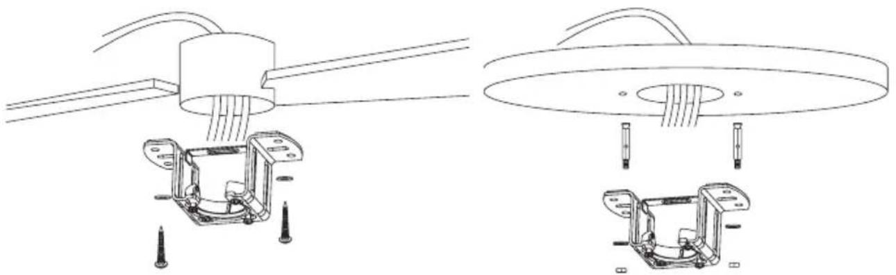
- Mark the correct position of the holes and fix the ceiling bracket using the screws with metal anchor or screws and washers suitable for the type of ceiling chosen.
- Check the correct installation of the bracket before hanging the fan. This plate must support the full weight of the fan.
Fixing the mounting bracket
The outlet box and joist must be securely mounted and capable of reliably supporting at least the weight of the fan.
natural_image
Technical line drawing of mechanical assembly with two views (top and side), no text or symbols presentWooden ceiling
Securely attach the mounting bracket with wood screws and washers to the ceiling joints.
Concrete ceiling
Bore holes with an 8mm drill, according to the length of the expansion screws. After that, fix the mounting bracket on the ceiling with the expansion screws.
Don't fix the mounting bracket directly on ceilings thinner than 10mm to avoid the risk of the wood screw becoming loose.
Downrod installation
Choose the suspension bar that best suits your situation: it has a 15 cm and a 25 cm suspension bar.
Remove the bar bolt, removing the pin, and pass the canopy (roof trim) and the engine canopy through the suspension bar. Next, route the fan motor cables through the inside of the suspension bar. Tighten the suspension bar to the engine and insert the bolt and pin.
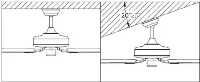
This fan can be installed both on a normal and a vaulted ceiling, and you can extend the hanging length using the longer downrod (provided). To install the downrod you will need the following tools: a screwdriver, a flat-head screwdriver, adjustable pliers or a wrench, a stepladder, wire cutters and rated electrical tape.
Feed the fan's wires all the way from the motor housing, through the downrod, the decorative cover and canopy to the ceiling.
Tip: Applying a small piece of electrical tape to the ends of the wires will help keep them together when threading them through the downrod.
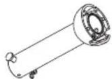
Attaching the downrod to the motor housing
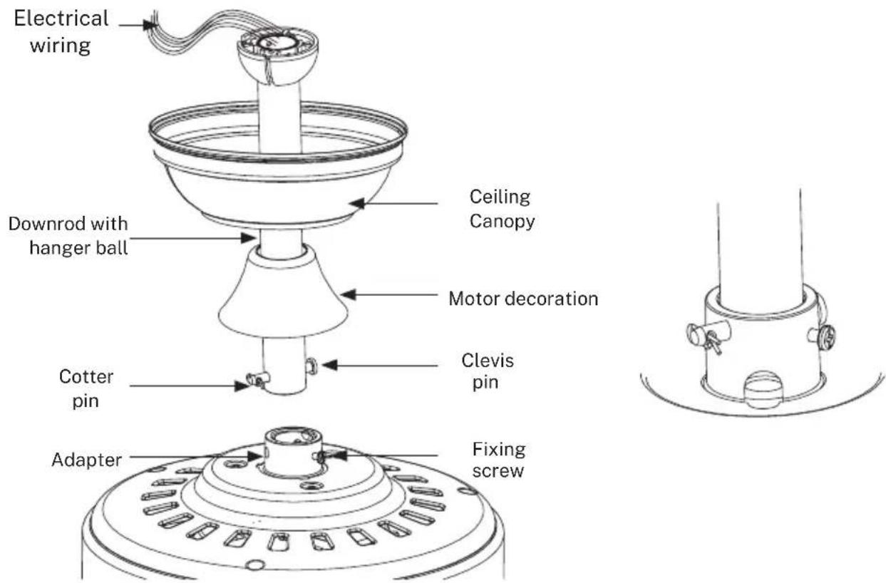
- Remove the cotter pin from the clevis pin and pull the clevis pin out.
- Unscrew the fixing screws.
- Push the downrod into the top of the motor housing and align the holes on the downrod.
- Insert the clevis pin back in and lock it with the cotter pin.
- Fasten the fixing screws.
- Cover with the motor canopy.
-
Fit two screws to the halfway position on opposite holes until there is approximately 5mm between the screw head and the rim of the mounting plate. Don't forget to place washers between the screw head and the mounting bracket.
-
Slide the canopy over the mounting bracket and align the locking slots with the two screws installed.
-
Twist the canopy and tighten the screws. Install the two remaining mounting screws into the other two holes on the canopy and tighten firmly.
natural_image
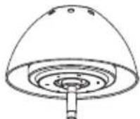
Technical line drawing of a mechanical component with concentric rings and a hanging bottle (no text or symbols)-
Once the electrical installation has been checked and completed, push the "ceiling rose" (ceiling trim) upwards until the ceiling mount and all the connection cables are covered. Match the screws by aligning the holes in the "ceiling rose" (ceiling trim) with the side holes in the bracket.
-
At this time you can also push the engine canopy down until it engages with the engine body.
Align the holes on the blade holder with the holes on the blades and the motor body and screw them in place (1), but don't tighten them until they are all placed and screwed in. Once the blades are tighten on the blade holder, screw the structure to the motor housing (2) until it is secured as in picture (3).
CEILING FAN WITH LED LIGHT
LED light panel and lamp shade assembly
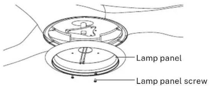
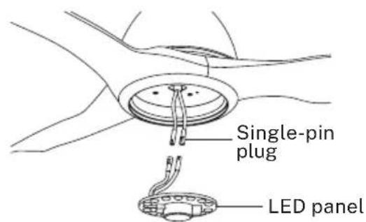
Unscrew a set screw. Attach the LED pan up to the bottom of the fan by inserting the other two set screw heads into the key hole slots. Rotate it to place, then secure the previous set screw by aligning the screw hole and the hole at the bottom of the fan, tighten the rest two set screws to secure the LED pan.
NOTE: While installing or removing the LED pan, please keep the insulation pads intact. Turning the set screws over-tightly or fastened will damage the insulation pads.
natural_image
Line drawing of a three-blade propeller with a central hub and rotating fan (no text or symbols)Restore the cover and the lamp shade back to the LED pan, and secure them with decorative clips and bolt nuts
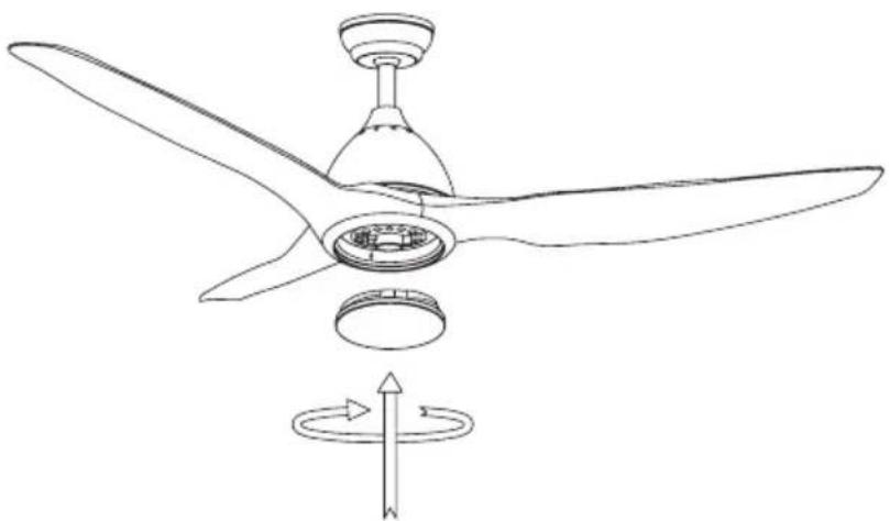
Installing the decorative cover
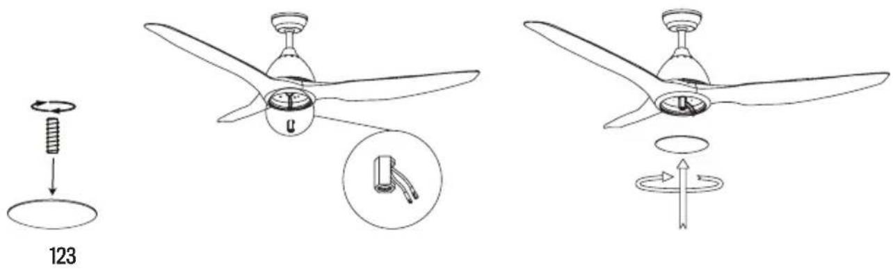
After installing the blades, align the decorative cover with the motor axis and screw it clockwise until it is securely fixed.
Check the installation
- Check the correct operation of the ceiling fan, checking that no strange movement or misalignment is observed in any part of the fan.
- In the event that some kind of hum / vibration can be seen, you can proceed to adjust the blades with the shooting kit.
- This kit has self-adhesive weights and "u" shaped clips.
- Turn off the ceiling fan.
- You can put the clip in the center of any blade and check if the vibration decreases.
- Turn on the fan and check. If no change is seen, turn off the fan and add another clip to a different blade or use the adhesive weights.
REMOTE CONTROL
- Speed control
- ** Light control button
- Off button
- On indicator light
- Timer
- Batteries
** Function only available when having the LED plate installed.

Warnings
- Use this product under the correct tension. Too low a voltage will result in a failed operation.
- Remove the batteries from the remote if you are not going to use it for a long time.
Note: For safety reasons and to ensure optimum performance, connect the ground wire correctly. - When installing the fan, make sure that nothing is pressing on the receiver antenna or other cables to prevent a short circuit.
When the remote control doesn't work, check if:
• The fan has power.
- The fan is properly connected.
- The battery in the remote control is charged.
- There are other products controlled by remote control nearby and in operation. Remote control products with the same frequency that are working in proximity will interfere with each other.
In compliance with Directives: 2012/19/EU and 2015/863/EU on the restriction of the use of dangerous substances in electric and electronic equipment as well as their waste disposal. The symbol with the crossed dustbin shown on the package indicates that the product at the end of its service life shall be collected as separate waste. Therefore, any products that have reached the end of their useful life must be given to waste disposal centres specialising in separate collection of waste electrical and electronic equipment, or given back to the retailer at the time of purchasing new similar equipment, on a one for one basis. The adequate separate collection for the subsequent start-up of the equipment sent to be recycled, treated and disposed of in an environmentally compatible way contributes to preventing possible negative effects on the environment and health and optimises the recycling and reuse of components making up the apparatus. Abusive disposal of the product by the user involves application of the administrative sanctions according to the laws.
natural_image
Simple line drawing of a bowl-shaped object with a circular base and two small dots at the top (no text or symbols)Florón
Barra de suspensión
Barra
natural_image
Technical line drawing of a mechanical bracket assembly (no text or symbols)Soporte de montaje
natural_image
Simple line drawing of a knife handle (no text or symbols)Aspas x3
natural_image
Line drawings of two remote control devices, one with a circular button and the other a rectangular device with a handle (no text or symbols)Mando a distancia
Opción con luz:
natural_image
Simple line drawing of a circular component with evenly spaced dots and a central bulb, no text or symbols present.Panel LEDPantalla decorativa
Opción sin luz:

natural_image
Technical line drawing of a mechanical assembly with no visible text or symbolsTechos de madera
natural_image
Technical line drawing of a ceiling lamp with internal components and a separate exploded view of the base frame (no text or symbols)- Remove the cotter pin from the clevis pin and pull the clevis pin out.
- Unscrew the fixing screws.
- Push the downrod into the top of the motor housing and align the holes on the downrod.
- Insert the clevis pin back in and lock it with the cotter pin.
- Fasten the fixing screws.
- Cover with the motor canopy.
natural_image
Technical line drawing of a mechanical device with a bowl and handle (no text or symbols)
natural_image
Technical line drawing of a mechanical component with no visible text or symbols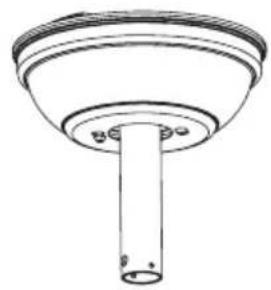
natural_image
Technical line drawing of a mechanical component with a cylindrical shaft and flange (no text or symbols)natural_image
Technical line drawing of a ceiling-mounted device with a hanging bottle (no text or symbols)natural_image
Line drawing of a three-blade propeller with a rotating base and directional arrow indicating rotation (no text or symbols)123
natural_image
Simple line drawing of a bowl-shaped object with a central hole and two small circular holes (no text or symbols)Canopla
Barra de cabide
Barra
natural_image
Technical line drawing of a mechanical bracket assembly (no text or symbols)Suporte de montagem

Guarnição do motor
Carcaça do motor
natural_image
Simple line drawing of a knife handle (no text or symbols)Pás x3
natural_image
Circular diagram with a central bulb and three wires, no text or symbols presentPainel de LEDTela
Opção sem luz:

natural_image
Technical line drawing of a mechanical assembly with no visible text or symbolsTelhados de madeira
Prenda firmemente o suporte de montagem com parafusos de madeira e arruelas nas vigas.
natural_image
Technical line drawing of a ceiling lamp with internal components and a close-up of the base frame (no text or symbols)Tetos de concreto / gesso
natural_image
Technical line drawings of three mechanical components with no visible text or symbolsnatural_image
Simple line drawing of a ceiling-mounted device with a hanging bottle (no text or symbols)natural_image
Line drawing of a three-blade propeller with a central hub and rotating fan (no text or symbols)123
natural_image
Simple line drawing of a bowl-shaped object with a circular base and two small dots at the bottom (no text or symbols)Canopée
Barre de suspension
Barre
natural_image
Technical line drawing of a mechanical bracket assembly (no text or symbols)Support de montage
Garniture du moteur

Carter moteur
natural_image
Simple line drawing of a curved, elongated object resembling a stylized tool or blade (no text or symbols)Pales x3

Boulons d'expansion
Support de lame
natural_image
Line drawings of two electronic devices: a remote control unit with two circular buttons and a portable device with three buttons (no text or symbols)Télécommande
natural_image
Circular diagram with a central bulb and internal dot pattern, no text or symbols presentnatural_image
Technical line drawing of a mechanical assembly with no visible text or symbolsToits en bois
natural_image
Technical line drawing of a ceiling lamp with internal components and a separate mechanical bracket (no text or symbols)natural_image
Technical line drawing of a mechanical device mounted on a bowl (no text or symbols)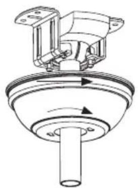
natural_image
Technical line drawing of a mechanical component with rotating shaft and housing (no text or symbols)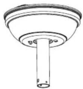
natural_image
Technical line drawing of a cylindrical mechanical component with a flanged top and base (no text or symbols)natural_image
Simple line drawing of a ceiling lamp with a hanging bottle (no text or symbols)natural_image
Line drawing of a three-blade propeller with a central hub and rotating fan (no text or symbols)natural_image
Simple line drawing of a bowl-shaped object with a central hole and two small dots, no text or symbols present.Rosone
Asta di sostegno
Asta di prolunga

natural_image
Technical line drawing of a mechanical bracket assembly (no text or symbols)Staffa di fissaggio
natural_image
Line drawing of a curved, elongated object resembling a tool or blade (no text or symbols)Pale x3
natural_image
Circular diagram with a central hole and two wires, no text or symbols presentPannello LEDSchermo decorativo
Opzione senza luce:

natural_image
Technical line drawing of a mechanical assembly with no visible text or symbolsTetti in legno
natural_image
Technical line drawing of a ceiling lamp with internal components and a close-up of the base frame (no text or symbols)Soffitti in cemento/intonaco
natural_image
Technical line drawings of three mechanical components with no visible text or symbolsnatural_image
Technical line drawing of a mechanical component with concentric rings and a hanging cylindrical part (no text or symbols)natural_image
Line drawing of a three-blade propeller with a central hub and rotating fan (no text or symbols)123
natural_image
Simple line drawing of a bowl-shaped object with a circular base and small circular top (no text or symbols)Rossete
Kleiderbügel
Bar
natural_image
Technical line drawing of a mechanical bracket assembly (no text or symbols)Montagehal- terung
Motorverkleidung
Motorgehäuse
natural_image
Simple line drawing of a curved, elongated object resembling a tool or tool handle (no text or symbols)Flügel x3
Dehnschrauben
Flügelunterstützung
natural_image
Line drawings of two electronic devices: a two-pin remote control box and a three-pin handheld device (no text or symbols)Fernbedi- enung
natural_image
Circular diagram with a central hole and evenly spaced dots, connected by a string (no text or symbols)natural_image
Technical line drawing of a mechanical assembly with no visible text or symbolsHolzdächer
natural_image
Technical line drawing of a ceiling lamp with internal components and a separate exploded view of the base (no text or symbols)Beton- / Gipsdecken
natural_image
Technical diagram showing two views of a mechanical component with a 20° angle标注 (no text or symbols present)natural_image
Three technical line drawings of a mechanical assembly, showing a bowl, valve, and cylindrical component (no text or symbols)natural_image
Technical line drawing of a mechanical component with concentric rings and a hanging bottle (no text or symbols)natural_image
Line drawing of a three-blade propeller with a central hub and rotating fan (no text or symbols)natural_image
Simple line drawing of a bowl-shaped object with a circular recess and two small protrusions at the bottom (no text or symbols)Overkapping
Ophangstang
Stang
natural_image
Technical line drawing of a mechanical bracket assembly (no text or symbols)Montagebeu- gel
Motorbekleding
Motorhuis

natural_image
Line drawing of a knife handle (no text or symbols)Bladen x3
natural_image
Line drawings of two electronic devices: a two-pin remote control unit and a three-pin remote device (no text or symbols)Afstandsbediening
natural_image
Simple line drawing of a circular component with evenly spaced dots and a central hole, connected by a string (no text or symbols)INSTALLATIE INSTRUCTIES
natural_image
Technical line drawing of a mechanical assembly with no visible text or symbolsHouten daken
natural_image
Technical line drawing of a ceiling lamp with internal components and a close-up of the base frame (no text or symbols)Beton / gipsplafonds
natural_image
Simple line drawing of a mechanical component with no text or symbols
natural_image
Technical line drawings of three mechanical components with no visible text or symbolsnatural_image
Technical line drawing of a ceiling-mounted device with a hanging cylindrical component (no text or symbols)natural_image
Line drawing of a three-blade propeller with a central hub and rotating fan (no text or symbols)natural_image
Simple line drawing of a bowl-shaped object with a central hole and two small holes (no text or symbols)Rozeta
Wieszak
drażek
natural_image
Technical line drawing of a mechanical bracket assembly (no text or symbols)Uchwyt mon- tażowy
Wykończenie silnika
Obudowa
silnika
natural_image
Line drawing of a knife handle (no text or symbols)topatki x3

Kołki rozporowe
Wsparcie
łopatki
natural_image
Two simple line drawings of remote control devices, one with two circular buttons and the other a rectangular device with three slots (no text or symbols)Pilot
natural_image
Circular diagram with a central hole and two wires, no text or symbols presentnatural_image
Technical line drawing of a mechanical assembly with no visible text or symbolsDachy drewniane
natural_image
Technical line drawing of a ceiling lamp and its internal mechanical housing (no text or symbols)natural_image
Technical line drawings of three mechanical components with no visible text or symbolsnatural_image
Simple line drawing of a ceiling-mounted device with a bottle suspended from the base (no text or symbols)natural_image
Line drawing of a three-blade propeller with a rotating base and directional arrow indicating rotation (no text or symbols)


- PORTUGUÊS
- SAFETY INSTRUCTIONS
- PARTS LIST
- Mechanical issues
- Electrical issues
- Remote control connection
- Hanging the fan
- INSTALLATION INSTRUCTIONS
- Fixing the mounting bracket
- Wooden ceiling
- Concrete ceiling
- Downrod installation
- Attaching the downrod to the motor housing
- CEILING FAN WITH LED LIGHT
- LED light panel and lamp shade assembly
- Installing the decorative cover
- Check the installation
- REMOTE CONTROL
- Warnings
- Techos de madera
- Telhados de madeira
- Tetos de concreto / gesso
- Toits en bois
- Tetti in legno
- Soffitti in cemento/intonaco
- Holzdächer
- Beton- / Gipsdecken
- INSTALLATIE INSTRUCTIES
- Houten daken
- Beton / gipsplafonds
- Dachy drewniane
Brand : Create
Model : Wind Sail
Category : Fan