Wind Easy - Fan Create - Free user manual and instructions
Find the device manual for free Wind Easy Create in PDF.

| Product type | Ceiling fan |
| Brand | Create |
| Model | Wind Easy |
| Minimum mounting height | 2.3 m from floor |
| Minimum lateral clearance | 0.76 m from walls or obstacles |
| Power supply | 220-240 V ~ 50 Hz |
| Motor power | 50 W (estimated) |
| Speeds | 3 speeds (pull chain control) |
| Lighting | Compatible lighting kit (bulb not included) |
| Blade material | MDF or plastic (not specified) |
| Number of blades | 5 (estimated) |
| Weight | Approximately 6 kg (estimated) |
| Insulation class | Class I (grounding required) |
| Protection rating | IP20 (indoor use only) |
| Installation | Flat or sloped ceiling (max 20°) |
| Control | Pull chain (direction reverse available) |
| Usage | Indoor only |
| Maintenance | Clean with a dry or slightly damp cloth (no solvents) |
| Replacement parts | Use exclusively CREATE parts |
| Warranty | 2 years (subject to conditions) |
Frequently Asked Questions - Wind Easy Create
User questions about Wind Easy Create
0 question about this device. Answer the ones you know or ask your own.
Ask a new question about this device
Download the instructions for your Fan in PDF format for free! Find your manual Wind Easy - Create and take your electronic device back in hand. On this page are published all the documents necessary for the use of your device. Wind Easy by Create.
USER MANUAL Wind Easy Create
natural_image
Line drawing of a multi-blade propeller with six blades and central hub (no text or symbols)CEILING FAN
USER MANUAL
CREATE CREATE CREATE ATE CREATE CREATE CRE CREATE CREATE CREATE ATE CREATE CREATE CRE CREATE CREATE CREATE ATE CREATE CREATE CRE CREATE CREATE CREATE ATE CREATE CREATE CRE CREATE CREATE CREATE ATE CREATE CREATE CRE CREATE CREATE CREATE ATE CREATE CREATE CRE CREATE CREATE CREATE ATE CREATE CREATE CRE CREATE CREATE CREATE ATE CREATE CREATE CRE CREATE CREATE CREATE ATE CREATE CREATE CRE CREATE CREATE CRE CREATE CREATE CRE CREATE CREATE CRE CREATE CREATE CRE
CREATE CREATE CREATE ATE CREATE CREATE CRE CREATE CREATE CREATE ATE CREATE CREATE CRE CREATE CREATE CREATE ATE CREATE CREATE CRE CREATE CREATE CREATE ATE CREATE CREATE CRE CREATE CREATE CREATE ATE CREATE CREATE CRE CREATE CREATE CREATE CREATE CREATE CREATE CREATE CREATE CREATE CREATE CREATE CREATE CREATE CREATE CREATE CREATE CREATE CREATE CREATE CREATE CREATE CREATE CREATE CREATE CREATE CREATE CREATE CREATE CREATE CREATE CREATE CREATE CREATE CREATE CREATE CREATE CREATE CREATE CREATE
INDEX
ENGLISH
Security instructions 6
Location and installation requirements 6
Mecanic problems 6
Electric problems 7
Cautions and warnings 7
List of parts 7
Electric connection 8
Installation instructions 8
Installation preparation 8
Post installation 9
Fixing the mounting bracket 9
Mount and hang the fan 10
Blade assembly 11
Installing the light kit 11
Mounting the rosette 12
Chain mounting 12
ESPAÑOL
Post-installation 30
Thank you for choosing our ceiling fan. Before using the appliance, and to ensure the best use, please read these instructions carefully.
The safety precautions included in this document reduce the risk of death, injury, and electric shock when properly followed. Keep the manual in a safe place for future reference, along with the complete warranty card, sales receipt, and package. If applicable, please forward these instructions to the next owner of the appliance. Always follow basic safety precautions and accident prevention measures when using an electrical appliance. We do not assume any responsibility for the breach of these requirements by the customer.
SECURITY INSTRUCTIONS
When using any electrical appliance, basic safety precautions should always be observed.
- This appliance is not designed for use by persons with reduced physical, sensory or mental disabilities or lack of experience and knowledge, unless they are under supervision or have been instructed in the safe use of the appliance and understand the dangers involved.
• Children do not recognize the dangers that can occur when operating a ceiling fan - Keep children away from ceiling fans.
- Do not expose the ceiling fan to rain or moisture. Do not use the ceiling fan outdoors or with wet hands.
LOCATION AND INSTALLATION REQUIREMENTS
MECANIC PROBLEMS
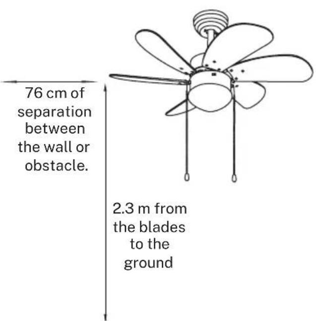
- According to safety regulations, the lowest point of the fan blade must be at least 2.3 m (7 ft) above the ground.
- Make sure the chosen location does not allow the rotating fan blades to come into contact with anything.
- Make sure the ceiling joists are solid and large and strong enough to support the weight of the fan.
- To reduce the risk of fire, electric shock, or personal injury, make sure the fan mounting bracket is connected directly to the building structure. DO NOT mount it in a distribution box.
- The mounting bracket must be firmly bolted to a supporting structure, for example a concrete ceiling, a steel structure or a wooden frame. If a wooden frame is added, it must be firmly nailed or screwed between two rafters.
- To reduce the risk of personal injury and property damage, do not bend or damage the fan rod or blades when handling or installing them.
- Make sure the ceiling fan is securely attached to the ceiling. All set screws should be checked and retightened as necessary prior to fan operation.
ELECTRIC PROBLEMS
• Always turn off the power before repairing the ceiling fan and turn off the circuit breaker that feeds the power to the light. To avoid possible electric shock, make sure the electricity is turned off at the fuse box or circuit breaker panel before wiring.
- The fan, mounting bracket, and light kit must be grounded. Make sure all spliced connections are adequately insulated.
- Check and confirm that all connections are correct and secure. When all electrical connections are made, store all cables in an orderly fashion.
- Do not attempt to control this fan from any wall switch or remote control that is not approved by the manufacturer for use with this fan. DO NOT use a solid state controller. Use of an unapproved remote control or wall switch will void the warranty.
- Do not connect the ceiling fan to a dimmer or dimmer.
CAUTIONS AND WARNINGS
- Use only CREATE replacement parts.
• To reduce the risk of personal injury, connect the fan directly to the building support structure in accordance with these instructions and use only the supplied hardware. - To avoid possible electrical shock, before installing your fan, disconnect power by turning off the circuit breakers in the outlet box and associated wall switch.
- All wiring must be in accordance with national and local electrical codes and ANSI / NFPA 70. If you are unfamiliar with wiring, contact a qualified electrician.
• To reduce the risk of personal injury, do not bend the blade clamping system when installing, balancing, or cleaning the fan. Never insert foreign objects between the rotating fan blades. - To reduce the risk of fire, electric shock, or motor damage, do not use a solid state speed control with this fan. Use only CREATE speed controls
Note: The important safety precautions and instructions in this manual are not intended to cover all possible conditions and situations that may occur. It should be understood that common sense and caution are necessary factors in the installation and operation of this fan.
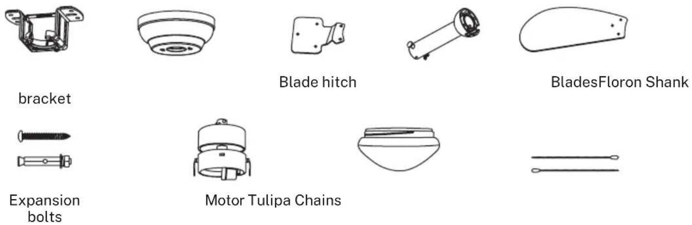
LIST OF PARTS
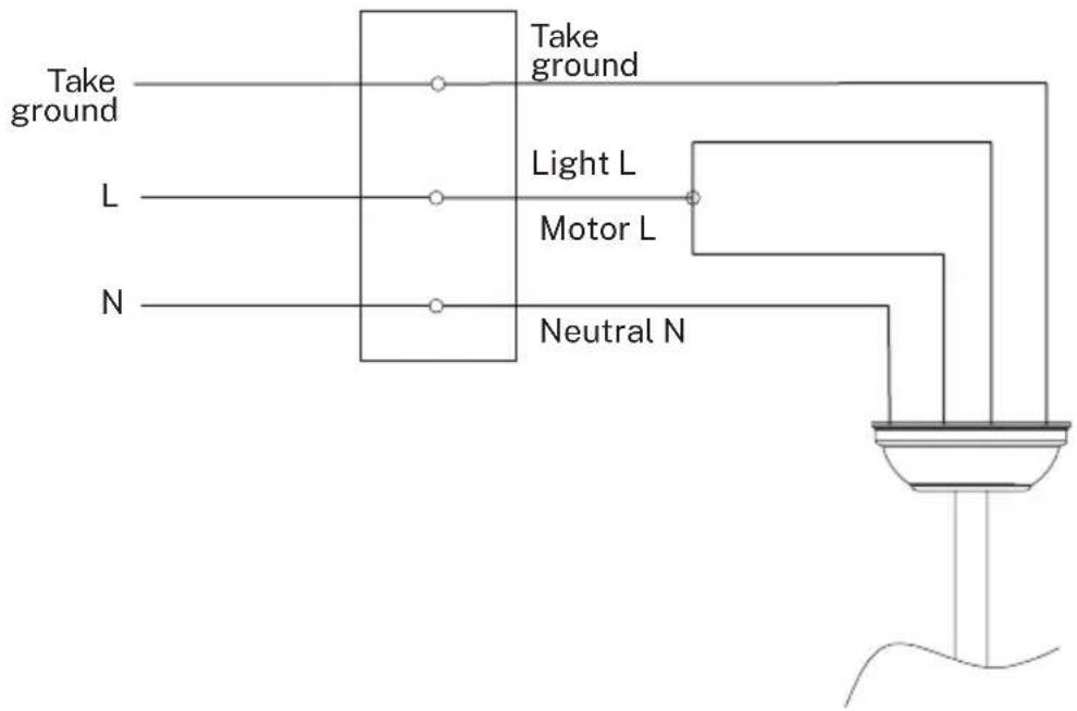
ELECTRIC CONNECTION
- Make the connection between the cables of the electrical installation of your home and the cables of the fan motor following the instructions below.
INSTALLATION INSTRUCTIONS
- Mark the correct position of the holes and fix the mounting bracket using the screws with metal plugs or screws and washers suitable for the type of ceiling chosen.
- Check the correct installation of the bracket before hanging the fan. This plate must support the full weight of the fan.
INSTALLATION PREPARATION
- To avoid personal injury and damage, make sure the place to hang the blades leaves a clearance of 2.3 m from the ground and 76 cm from any walls or obstacles.
- Make sure the mounting bracket is securely attached to the building structure and can support the full weight of the fan.
POST INSTALLATION
- Remove the bolt from the seatpost, removing the pin and pass the finial (crown molding) and hood through the hanger bar. Next, route the fan motor wires through the inside of the hanger bar. Tighten the hanger bar to the engine and insert the bolt and pin.
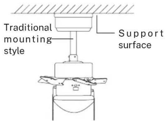
The standard mount hangs from the ceiling using a rod.
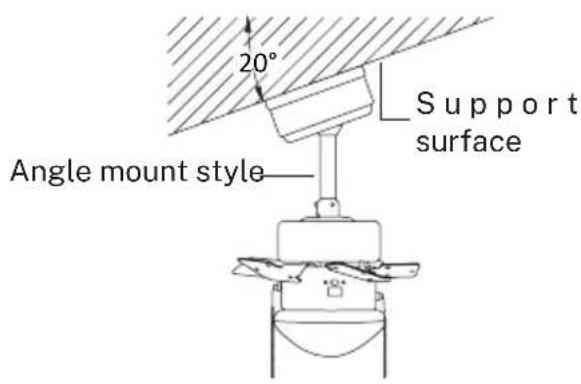
Angle mounting is recommended for a vaulted or angled ceiling.
FIXING THE MOUNTING BRACKET
- The outlet box and beam must be securely mounted and capable of reliably supporting at least the weight of the fan.
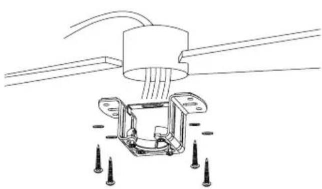
natural_image
Technical line drawing of a mechanical assembly with mounting flanges and screw fasteners (no text or symbols)Wood roof
Securely attach the mounting bracket with wood screws and washers to the ceiling joints.
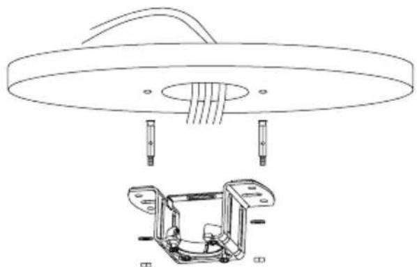
natural_image
Technical line drawing of a ceiling lamp with internal components and a close-up of the base frame (no text or symbols)Concrete ceiling
Drill holes with an 8mm drill, depending on the length of the expansion screws. Next, secure the mounting bracket to the ceiling with the expansion screws.
Do not fix the mounting bracket directly on ceilings with a thickness less than 10mm to avoid the risk of the screw loosening.
MOUNT AND HANG THE FAN
- If you want to extend the suspension length of your fan, you must remove the hanging ball from the rod provided for use with the extension rod (included).
(If you want to use the downrod, follow the instructions below.)
- To remove the hanging ball, loosen the hanging ball set screw and remove the pin and bolt. Lower the hanging ball and remove the stopper pin. Slide the hanging ball out of the original rod and slide it down the longest rod (it should be noted that the top of the rod has a hole for the set screw, use this hole when inserting the set screw).
- Insert the stopper pin into the top of the extended rod and lift off the hanging ball.
- Make sure the stopper pin aligns with the slots on the inside of the hanging ball, securely tighten the set screw.
Tip: To make it easier to feed the wires into the bar, wrap some electrical tape around the wires. This will help you hold them together as you insert them into the bar.
- Loosen set screws and washer on top of motor housing. Remove the pins from the bar (if you haven't already). Insert the rosette through the bar.
• Pass the cables through the bar and pull the excess cables from the top of the bar to tighten them. - Place the bar inside the motor housing and insert the pins you removed earlier. Tighten the set screws and washers.
• Lower the rosette onto the motor housing.
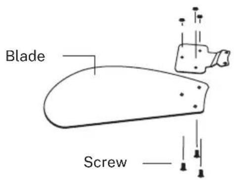
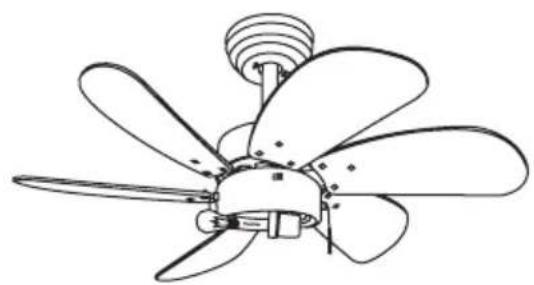
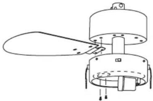
BLADE ASSEMBLY
Align the holes in the blade bracket with the holes in the blades and motor body and screw them into place, but do not tighten the screws until they are all in place and screwed in.
①

natural_image
Technical line drawing of a mechanical component with no visible text or symbols②
- Check the correct operation of the ceiling fan, checking that there are no strange movements or misalignments in any part of the fan.
- In the event that any type of hum / vibration can be seen, you can proceed to adjust the blades with the anti-roll kit.
- The anti-roll kit has self-adhesive weights and u-shaped clips.
- Turn off the ceiling fan.
- You can put the clip in the center of any blade and check if the vibration decreases.
- Turn on the fan and check. If there are no changes, turn off the fan and add another.
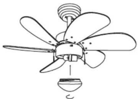
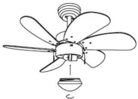
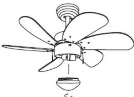
INSTALLING THE LIGHT KIT
natural_image
Line drawing of a five-bladed propeller with a central hub and top screw (no text or symbols)①

natural_image
Line drawing of a multi-blade propeller with a bulb and fan (no text or symbols)2
• Install the bulb (not included).
- Attach the lampshade to the motor by inserting the glass neck into the light fixture, keeping two spring clips inside the glass neck. Pull the glass shade towards the third spring clip. Push the third clip to fit inside the glass and push the glass towards the mounter.
- Assemble the decorative keychain and extension chains from the hardware bag to the fan pull chains by inserting the end of the chain into the chain link. Confirm that the chains are secure by pulling lightly on both chains on the coupling.
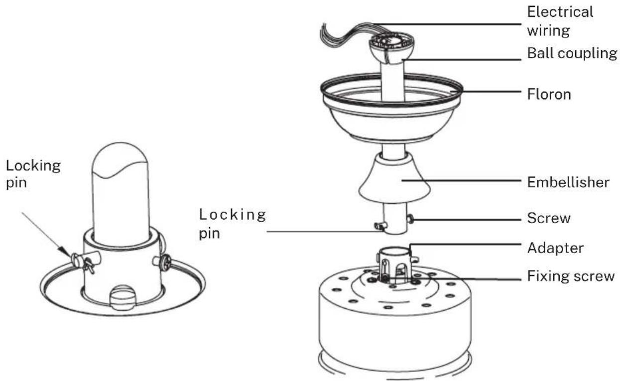
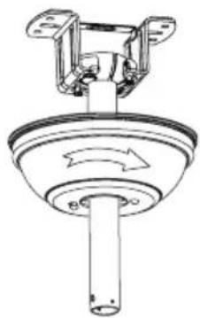
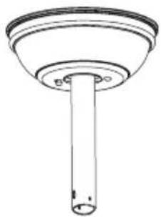
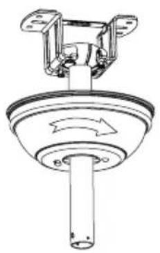
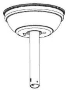
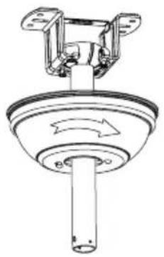
MOUNTING THE ROSETTE

natural_image
Technical line drawing of a ceiling-mounted device with mounting bracket and cylindrical base (no text or symbols)1
natural_image
Technical line drawing of a mechanical component with rotating arrows (no text or symbols)2
natural_image
Simple line drawing of a cylindrical object with a flanged top and circular base (no text or symbols)③
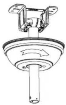
- Raise the rosette up to the mounting bracket and align the loosened screws in the mounting bracket with the holes in the rosette.
- Rotate the fin to adjust. Reinsert the screws and secure with a screwdriver.
- Once you have the mounting bracket secured to the junction box you can proceed to hang the fan.
- Hold the fan firmly with both hands. Pass the rod through the mounting bracket opening and let the ball rest on the mounting bracket.
- Rotate the ball coupling until it lines up with the tab on the mounting bracket.
- Tip: Someone else should help you hold the ladder and hand you the fan after you get on it.
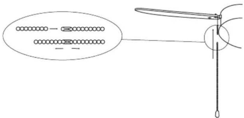
CHAIN MOUNTING
Hook the pin at the end of the chain into the slot and pull to tighten. After that, you can turn it on to electricity and enjoy your new fan.
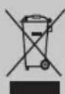
In compliance with Directives: 2012/19/EU and 2015/863/EU on the restriction of the use of dangerous substances in electric and electronic equipment as well as their waste disposal. The symbol with the crossed dustbin shown on the package indicates that the product at the end of its service life shall be collected as separate waste. Therefore, any products that have reached the end of their useful life must be given to waste disposal centres specialising in separate collection of waste electrical and electronic equipment, or given back to the retailer at the time of purchasing new similar equipment, on a one for one basis. The adequate separate collection for the subsequent start-up of the equipment sent to be recycled, treated and disposed of in an environmentally compatible way contributes to preventing possible negative effects on the environment and health and optimises the recycling and reuse of components making up the apparatus. Abusive disposal of the product by the user involves application of the administrative sanctions according to the laws.
natural_image
Technical line drawing of a mechanical assembly with bolts and a central component (no text or symbols)Techo de madera
natural_image
Technical line drawing of a ceiling lamp with internal components and a close-up of the base frame (no text or symbols)Techo de hormigón
natural_image
Technical line drawing of a mechanical component with no visible text or symbols②
natural_image
Line drawing of a multi-blade propeller with six blades and a central hub (no text or symbols)①
natural_image
Line drawing of a multi-blade propeller with fan blades and a bulb (no text or symbols)2
natural_image
Technical line drawing of a mechanical component with a cylindrical shaft and mounting bracket (no text or symbols)①
natural_image
Technical line drawing of a mechanical component with rotating shaft and mounting bracket (no text or symbols)②

natural_image
Simple line drawing of a cylindrical object with a flanged top and base (no text or symbols)③
natural_image
Technical line drawing of a mechanical assembly with mounting holes and wiring (no text or symbols)Telhado de madeira
natural_image
Technical line drawing of a ceiling lamp with internal components and a separate exploded view of the base frame (no text or symbols)Teto de concreto
natural_image
Technical line drawing of a mechanical component with no visible text or symbols②
natural_image
Line drawing of a six-bladed propeller fan with a spiral top and central hub (no text or symbols)1

natural_image
Line drawing of a multi-blade propeller fan with a bulb and internal blades (no text or symbols)2
natural_image
Technical line drawing of a mechanical component with a cylindrical shaft and mounting bracket (no text or symbols)①

natural_image
Technical line drawing of a mechanical component with rotating shaft and mounting bracket (no text or symbols)2

natural_image
Simple line drawing of a cylindrical object with a flanged top and base (no text or symbols)③
natural_image
Technical line drawing of a mechanical assembly with mounting holes and wiring (no text or symbols)Toit en bois
natural_image
Technical line drawing of a ceiling lamp with internal components and a separate exploded view of the base frame (no text or symbols)Plafond en béton
natural_image
Technical line drawing of a mechanical component with no visible text or symbols②
natural_image
Line drawing of a five-bladed propeller with a spiral top and central hub (no text or symbols)①

natural_image
Line drawing of a multi-blade propeller with a bulb and fan base (no text or symbols)2
natural_image
Technical line drawing of a mechanical component with a cylindrical shaft and mounting bracket (no text or symbols)①
natural_image
Technical line drawing of a mechanical component with rotating shaft and mounting bracket (no text or symbols)2

natural_image
Simple line drawing of a cylindrical object with a flanged top and base (no text or symbols)③
natural_image
Technical line drawing of a mechanical assembly with screws and a central component (no text or symbols)Tetto in legno
natural_image
Technical line drawing of a ceiling lamp with internal components and a 3D exploded view of the base panel (no text or symbols)Soffitto in cemento
①
natural_image
Technical line drawing of a mechanical device with no visible text or symbols②
natural_image
Line drawing of a five-bladed propeller with a central hub and top screw (no text or symbols)1

natural_image
Line drawing of a multi-blade propeller with a bulb and fan (no text or symbols)2
natural_image
Technical line drawing of a mechanical component with a cylindrical shaft and mounting bracket (no text or symbols)①

natural_image
Technical line drawing of a mechanical component with rotating shaft and mounting bracket (no text or symbols)②
natural_image
Simple line drawing of a cylindrical object with a flanged top and base (no text or symbols)③
natural_image
Technical line drawing of a mechanical assembly with mounting holes and wiring (no text or symbols)Holzdach
natural_image
Technical line drawing of a ceiling lamp with internal components and a 3D exploded view of the base panel (no text or symbols)Betondecke
natural_image
Technical line drawing of a mechanical component with no visible text or symbols②
natural_image
Line drawing of a five-bladed propeller with a spiral top and central hub (no text or symbols)①
natural_image
Line drawing of a multi-blade propeller with a bulb and fan base (no text or symbols)2
natural_image
Technical line drawing of a mechanical component with a cylindrical shaft and mounting bracket (no text or symbols)①
natural_image
Technical line drawing of a mechanical component with rotating shaft and mounting bracket (no text or symbols)②

natural_image
Simple line drawing of a cylindrical object with a flanged top and base (no text or symbols)③

INSTALLATIE INSTRUCTIES
natural_image
Technical line drawing of a mechanical assembly with mounting flanges and screw fasteners (no text or symbols)Houten dak
natural_image
Technical line drawing of a ceiling lamp with internal components and a separate exploded view of the base frame (no text or symbols)Betonnen plafond
natural_image
Technical line drawing of a mechanical component with no visible text or symbols②
natural_image
Line drawing of a six-bladed propeller fan with a spiral top and central hub (no text or symbols)①

natural_image
Line drawing of a multi-blade propeller fan with a bulb and internal blades (no text or symbols)2
natural_image
Technical line drawing of a mechanical component with a cylindrical shaft and mounting bracket (no text or symbols)1

natural_image
Technical line drawing of a mechanical component with rotating shaft and mounting bracket (no text or symbols)2

natural_image
Simple line drawing of a cylindrical object with a flanged top and base (no text or symbols)③

natural_image
Technical line drawing of a mechanical assembly with mounting holes and wiring (no text or symbols)Dach drewniany
natural_image
Technical line drawing of a ceiling lamp with internal components and a separate exploded view of the base frame (no text or symbols)Sufit betonowy
natural_image
Technical line drawing of a mechanical device with no visible text or symbols②
natural_image
Line drawing of a multi-blade propeller with six blades and a central hub (no text or symbols)1
natural_image
Line drawing of a multi-blade propeller with a base and fan assembly (no text or symbols)2
natural_image
Technical line drawing of a mechanical component with a cylindrical shaft and mounting bracket (no text or symbols)①

natural_image
Technical line drawing of a mechanical component with rotating shaft and mounting bracket (no text or symbols)2

natural_image
Simple line drawing of a cylindrical object with a flanged top and base (no text or symbols)③