USER MANUAL Wind Calm Create
Location and installation requirements 6
Safety instructions 7
WIND CALM WITH LED LIGHT
List of parts 8
Installation instructions 9
Remote control 9
WIND CALM WITHOUT LED LIGHT
List of parts 12
Installation instructions 12
Remote control 14
App convection 15
PORTUGUÊS
WIND CALM SEM LUZ LED
Lista de peças 32
Thank you for choosing our ceiling fan. Before using the appliance, and to ensure the best use, please read these instructions carefully.
The safety precautions included in this document reduce the risk of death, injury, and electric shock when properly followed. Keep the manual in a safe place for future reference, along with the complete warranty card, sales receipt, and package. If applicable, please forward these instructions to the next owner of the appliance. Always follow basic safety precautions and accident prevention measures when using an electrical appliance. We do not assume any responsibility for the breach of these requirements by the customer.
LOCATION AND INSTALLATION REQUIREMENTS
MECHANICAL ISSUES
- According to safety regulations, the lowest point of the fan blade must be at least 2.3m (7 feet) from the floor.
- Please make sure the chosen location will not allow the rotating fan blades to come into contact with any objects.
- Ensure ceiling joists are sound and are large and strong enough to support the weight of the fan.
- To reduce the risk of fire, electric shock or personal injury, ensure that the fan mounting bracket is attached directly to the building structure. DO NOT mount to an outlet box.
- The mounting bracket must be firmly screwed to a load bearing structure, e.g. a concrete ceiling, steel structure or timber frame. If a timber frame is added, it must be securely nailed or screwed between two beams.
- To reduce risk of personal injury and property damage, do not bend or damage the downrod or the fan blades when handling or installing them. If you notice any product imperfections, please contact our after-sales service before proceeding to install the fan.
- Make sure the ceiling fan is securely fastened to the ceiling. All set screws must be checked and re-tightened where necessary before fan operation.
ELECTRICAL ISSUES
- Always turn the power off before servicing the ceiling fan, and turn off the circuit breaker that feeds the power to the light. To avoid possible electric shock, make sure electricity is turned off at the fuse box or circuit breaker panel before wiring.
- The fan, mounting bracket and light kit must be earthed. Ensure all spliced connections are adequately insulated.
- Check and confirm that all connections are proper and secure. When all the electrical connections are done, store all wires neatly.
- Do not attempt to control this fan from any wall switch or remote control that is not approved by the manufacturer for use with this fan. DO NOT use a solid state controller. The use of an unapproved wall switch or remote control will void the warranty.
- Do not connect the ceiling fan to a dimmer switch or a regulator.
When using any electrical appliance, basic safety precautions should always be observed.
- Read this entire manual carefully before beginning installation. Save these instructions.
- To reduce the risk of personal injury, attach the fan directly to the support structure of the building according to these instructions, and use only the hardware supplied.
- To avoid possible electrical shock, before installing your fan, disconnect the power by turning off the circuit breakers to the outlet box and associated wall switch location. If you cannot lock the circuit breakers in the off position, securely fasten a prominent warning device, such as a tag, to the service panel.
- All wiring must be in accordance with national and local electrical codes and ANSI/NFPA 70. If you are unfamiliar with wiring, use a qualified electrician.
- Do not bend the blade attachment system when installing, balancing, or cleaning the fan.
- Never insert foreign objects between rotating fan blades.
- To reduce the risk of fire, electrical shock, or motor damage, do not use a solid-state speed control with this fan. Use only original speed controls.
- This appliance can be used by children aged from 8 years old and above and persons with reduced physical, sensory or mental capabilities or lack of experience and knowledge if they have been given supervision or instruction concerning use of the appliance in a safe way and understand the hazards involved.
- Children shall not play with the appliance.
- Cleaning and user maintenance shall not be made by children unless they are older than 8 and supervised. Close supervision is necessary when any appliance is used by or near children.
WIND CALM WITH LED LIGHT
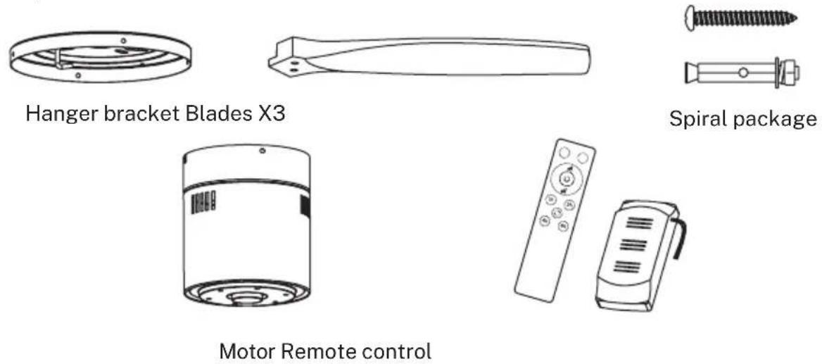
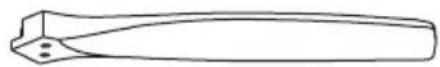
LIST OF PARTS
Carefully open the packaging and remove all the items included. Place them on a carpet or a big piece of plastic to avoid any damage.
Check that all the items listed below have been included.
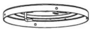
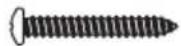
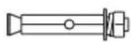
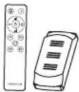
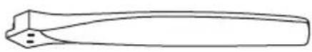
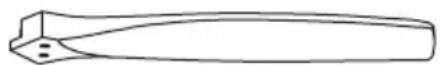
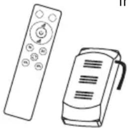
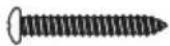
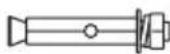
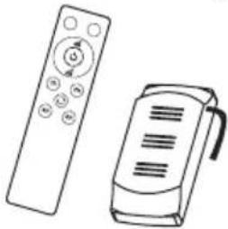
Expansion screwsHanger bracket Remote control
+ driver
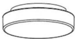
natural_image
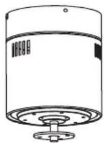
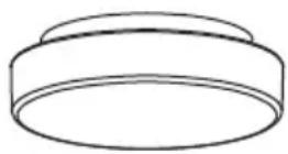
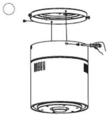
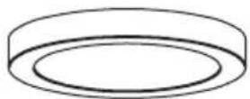
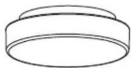
Line drawing of a cylindrical device with a flanged base and top panel (no text or symbols)
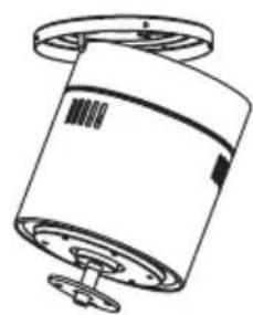
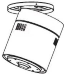
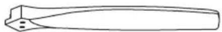
Motor Blades

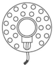
Connections panel

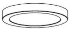
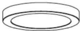
natural_image
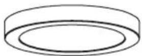
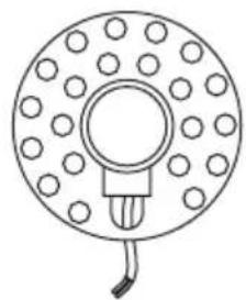
Simple line drawing of a circular component with evenly spaced dots and a central bulb (no text or symbols)
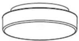
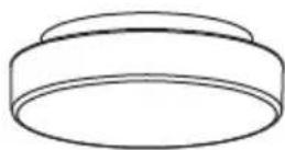
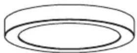
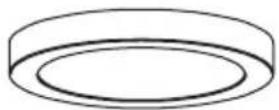
LED panelDecorative shade
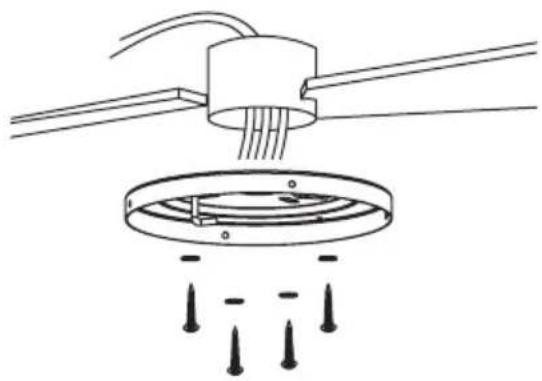
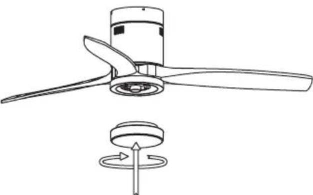
INSTALLATION INSTRUCTIONS
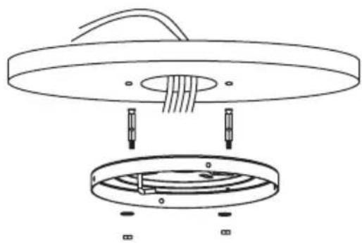
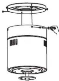
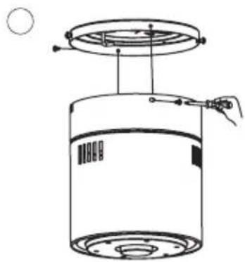
FIXING THE MOUNTING BRACKET
The outlet box and joist must be securely mounted and capable of reliably supporting at least the weight of the fan.
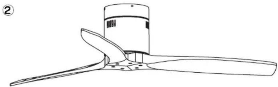
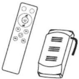
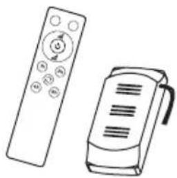
REMOTE CONTROL
- Light
- Light intensity control
- Fan intensity control
- Timer
- Batteries (2 x AAA)
- Colour temperature control
- ON / OFF button
- Reverse function
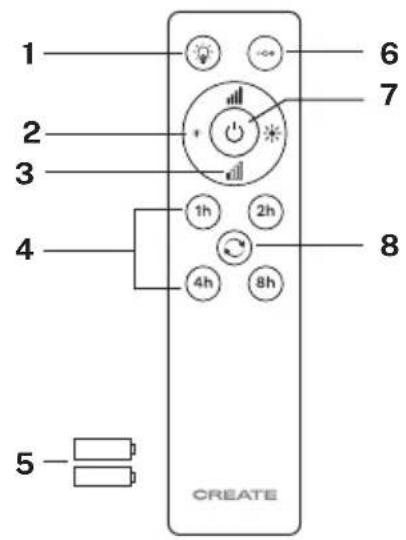
- Turn on the fan by pressing the ON / OFF button
- Change air flow direction (winter/summer function) by pressing Reverse button with the fan on. It does not work when the fan is off. The blades will stop spinning to start again in the opposite direction just pressing the button once.
- Turn the light on and off pressing Light button.
- Pess Power levels button to increase the speed of the fan once it is on.
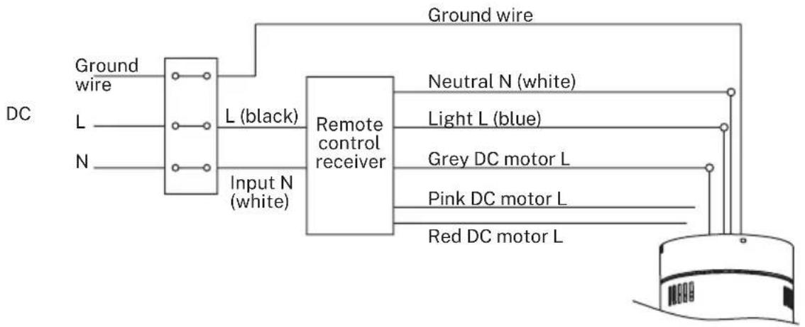
REMOTE CONTROL CONNECTION
flowchart
graph LR
    A["Ground wire"] --> B["DC"]
    C["L (black)"] --> B
    D["N (white)"] --> B
    B --> E["Input N (white)"]
    E --> F["Remote control receiver"]
    F --> G["Neutral N (white)"]
    F --> H["Light L (blue)"]
    F --> I["Grey DC motor L"]
    F --> J["Pink DC motor L"]
    F --> K["Red DC motor L"]
    G --> L["Ground wire"]
    H --> L
    I --> L
    J --> L
    K --> L
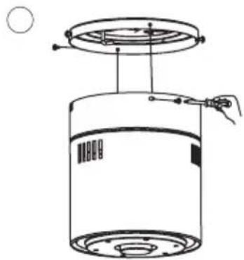
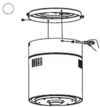
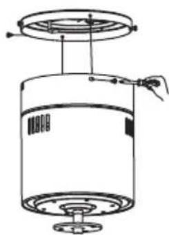
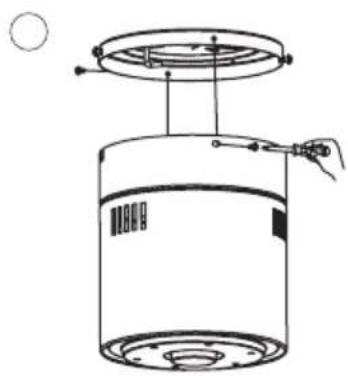
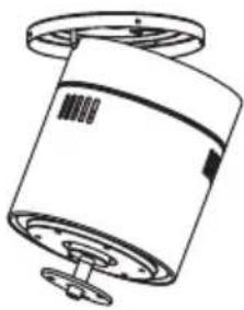
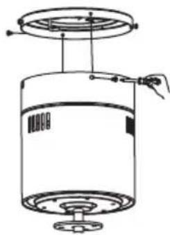
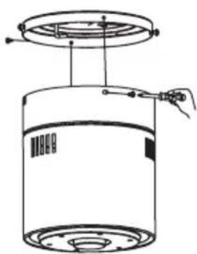
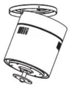
Receiver placement: Attach the motor on the left hook and then conduct the wiring.
natural_image
Technical line drawing of a cylindrical device with a lid and base, showing internal components without any text or symbols.
123
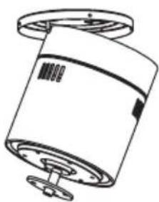
natural_image
Technical line drawing of a cylindrical mechanical component with mounting flanges (no text or symbols)
O
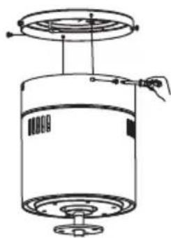
natural_image
Technical line drawing of a cylindrical device with a top panel and base, showing internal components and wiring (no text or symbols)
O
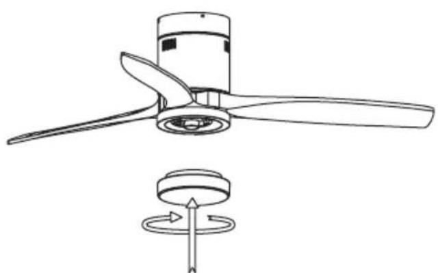
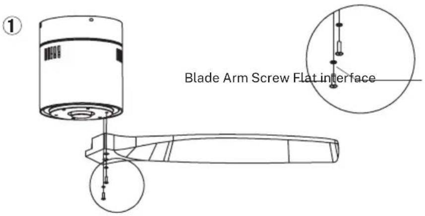
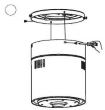
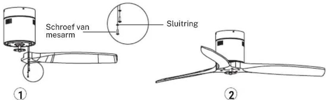
BLADES ASSEMBLY
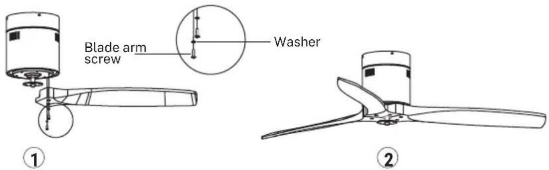
Tip: Washers for blade screws can be set on each blade screw prior to installing blades. Align the blade holes with the motor screw holes. Tighten all the screws once all the blades are attached. Before securing screws permanently, repeat with remaining blade arms.
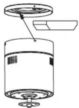
CONNECTIONS PANEL ASSEMBLY
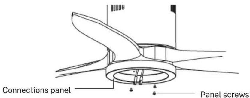
Attach the connections plate up to the bottom of the fan by inserting the set screw heads into the key hole slots. Rotate them to place and tighten them to secure the plate.
LED LIGHT PANEL AND LAMP SHADE ASSEMBLY
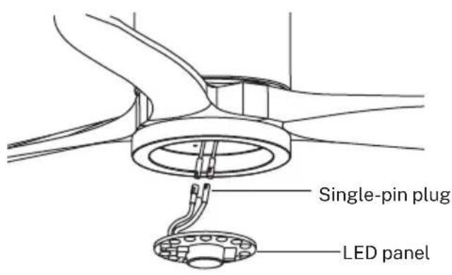
natural_image
Technical line drawing of a propeller with three blades and a rotating base (no text or symbols)
Connect the single-pin plugs of the connections plate with the ones on the LED panel. The LED panel is magnetized so it will be attached to the connections panel just by placing them together.
Note: While installing or removing the LED plate, please keep the insulation pads intact carefully. Turning the set screws over-tightly or fast will damage the insulation pads.
Screw the lamp shade back to the connections plate.
CHECK THE INSTALLATION
- Check the correct operation of the ceiling fan, checking that no strange movement or misalignment is observed in any part of the fan.
- In the event that some kind of hum / vibration can be seen, you can proceed to adjust the blades with the shooting kit.
- This kit has self-adhesive weights and "u" shaped clips.
- Turn off the ceiling fan.
- You can put the clip in the center of any blade and check if the vibration decreases.
- Turn on the fan and check. If no change is seen, turn off the fan and add another clip to a different blade or use the adhesive weights.
WIND CALM WITHOUT LED LIGHT
LIST OF PARTS
Carefully open the packaging. Remove items from Styrofoam inserts. Remove motor housing and place on carpet or Styrofoam to avoid damage to finish. Check against parts inventory that all parts have been included.
INSTALLATION INSTRUCTIONS
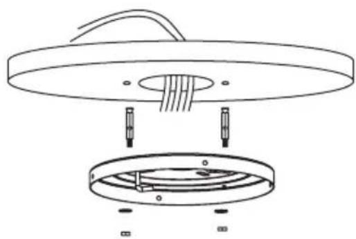
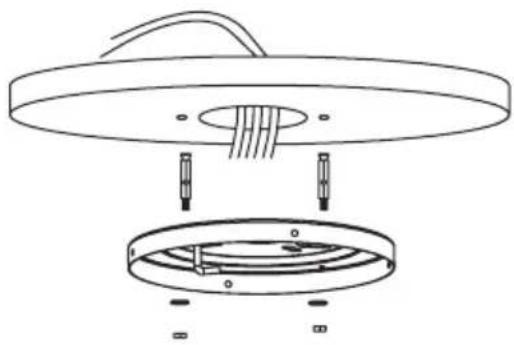
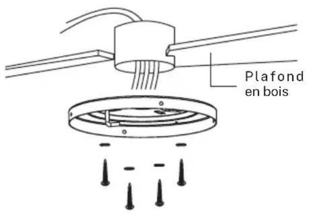
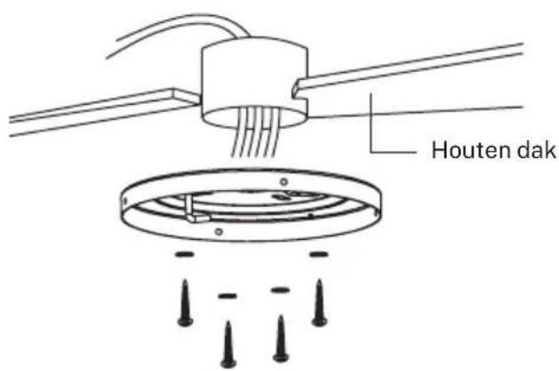
FIXING THE MOUNTING BRACKET
The outlet box and joist must be securely mounted and capable of reliably supporting at least the weight of the fan.
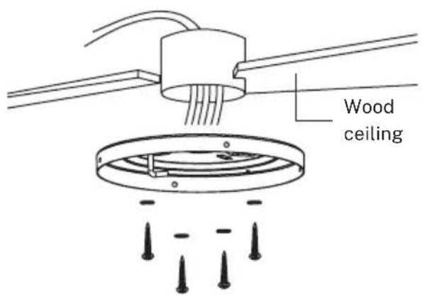
natural_image
Diagram of a ceiling lamp with three wires and a circular base, showing no text or symbols
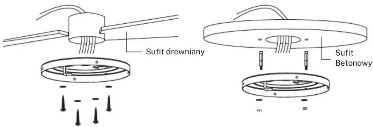
Wooden ceiling
Securely attach the mounting bracket with wood screws and washers to the ceiling joints.
natural_image
Technical line drawing of a mechanical assembly with no visible text or symbols
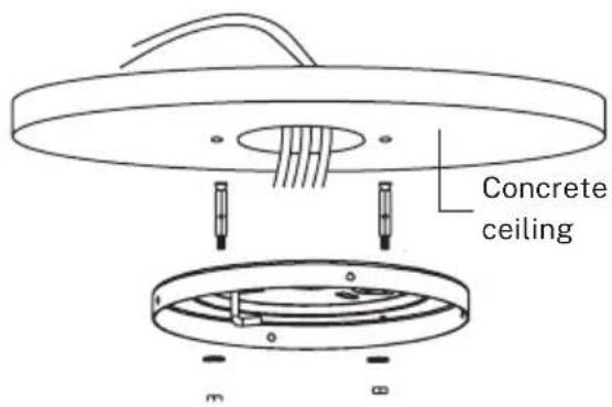
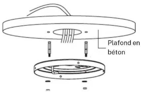
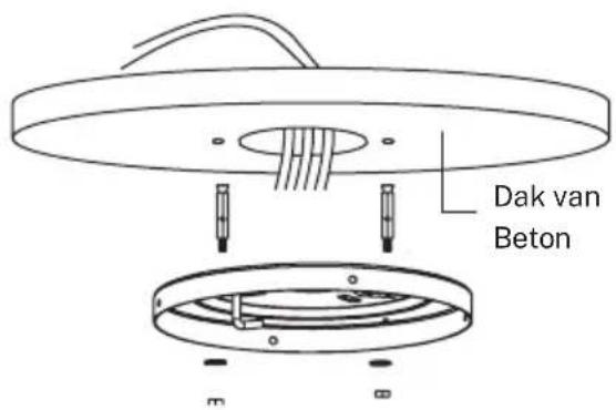
Concrete ceiling
Bore holes with an 8mm drill, according to the length of the expansion screws. After that, fix the mounting bracket to the ceiling with the expansion screws.
Don't fix the mounting bracket directly on ceilings thinner than 10mm to avoid the risk of the screw coming loose.
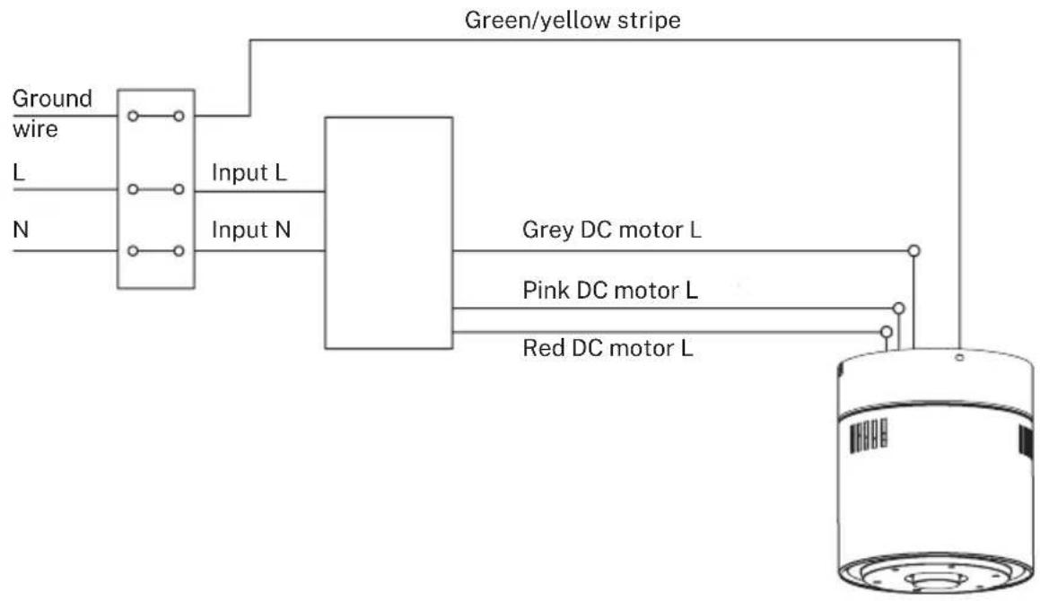
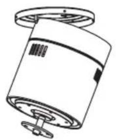
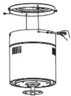
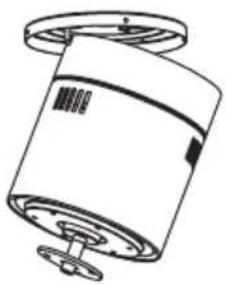
REMOTE CONTROL CONNECTION
flowchart
graph TD
    A["Ground wire"] --> B["Input L"]
    C["L"] --> B
    D["N"] --> B
    B --> E["Green/yellow stripe"]
    E --> F["Grey DC motor L"]
    E --> G["Pink DC motor L"]
    E --> H["Red DC motor L"]
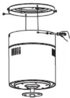
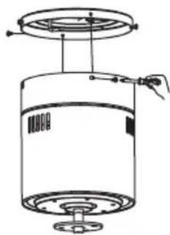
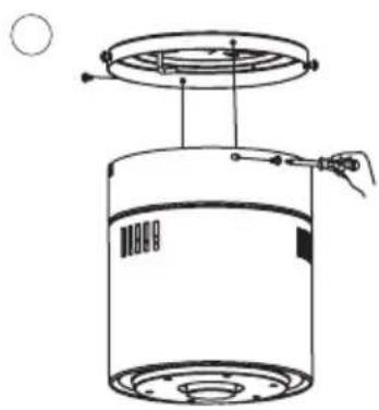
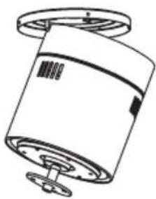
Receiver place: Hook the motor on the left hook, and then conduct wiring
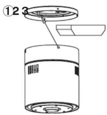
natural_image
Technical line drawing of a cylindrical mechanical component with a flanged top and base (no text or symbols)
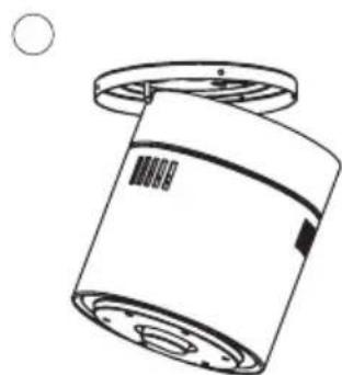
natural_image
Technical line drawing of a cylindrical device with internal components and a handle, no text or symbols present
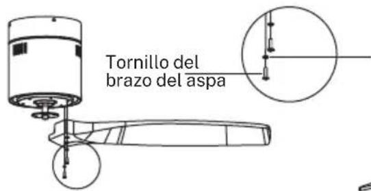
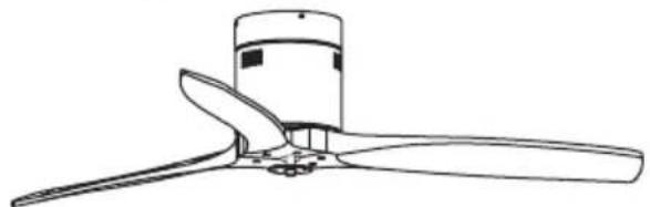
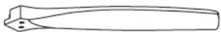
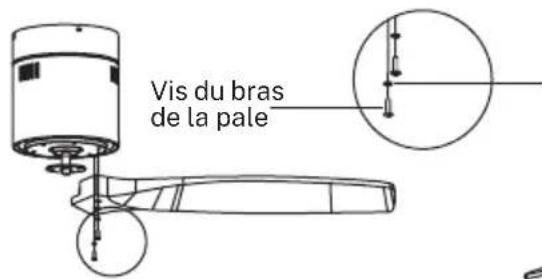
BLADE ASSEMBLY
Time Saver: Washers for blade screws can be set on each blade screw prior to installing-blades.
Align blade holes with motor screw holes, then securely tighten all the screws once all the blades are attached. Before securing screws permanently, repeat with remaining blade arms.
Note: Tighten blade screws twice.
natural_image
Line drawing of a propeller with three blades and a central hub (no text or symbols)
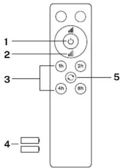
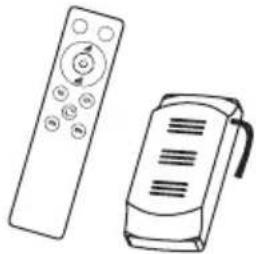
REMOTE CONTROL
RF wireless digital transmission, two-way control, coincident code rate is less than one millionth.(Transmitter and receiver must be sent back to factory for maintenance if damaged.) The remote control can control the receiver from any angle or direction up to the stated limit distance.
- ON / OFF button
- Fan speed control
- Timer
- Batteries (2 x AAA)
- Reverse function
Blank buttons only work with LIGHT models.
PLEASE REMEMBER:
- If the remote control is not working, please check the batteries are in the correct position and fully charged.
- If the remote control is not working, please whether there are any similar remote controlled products nearby and running, because remote controls using the same frequency will interfere with each other's signals.
- If the battery is low this will affect the sensitivity of the transmitter and weaken signal reception (the indicator light will flash to warn when the battery is low). Batteries must be replaced if low,
- Please remove the battery from the remote control if it will not be used for a long time.
- For the maximum electricity voltage, see the above "POWER PARAMETER LIST"
Please connect the ground wire correctly, otherwise it may cause the lights to dim or flicker.
- When installing the fan, make sure the fan ceiling cover does not place any pressure on the antenna (or other wire), which may damage the wire and cause a short circuit.
APP CONECTION
The CREATE application is available for Android and iOS (look for the app on Google Play or App Store or scan the QR code below). Depending on the provider, there may be costs involved in downloading the app.
This appliance allows you to operate the appliance via your home network. A prerequisite is a permanent 2.4Gh WiFi connection to your router and the free CREATE app. (Current internet providers offer both 5Gh and 2.4Gh simultaneously.)
We recommend disconnecting the appliance from the power supply when you are away from home to prevent unintentional switching on while you are away.

OS iPhone OS Android

HOW TO CONNECT TO THE APP
- Install the CREATE app and create a user account.
- Set up a login password and log in the app.
- Click on "Add device" (+) and then on the category corresponding to the ceiling fan.
- On the remote control, press and hold the 1H and 4H buttons for 5 seconds (more or less) until you hear a beep sound.
- After that, click on "Confirm".
- Enter your WiFi network password and confirm.
- While connecting, make sure your router, mobile phone and device are as close as possible. After that, your ceiling fan will be successfully paired to your CREATE app.
natural_image
Simple line drawing of a circular component with evenly spaced dots and a central hole, no text or symbols present.
Panel LEDPantalla decorativa
natural_image
Technical line drawing of a cylindrical device with a lid and base plate (no text or symbols)
123
natural_image
Technical line drawing of a mechanical component with no visible text or symbols
O
natural_image
Technical line drawing of a cylindrical industrial vessel with a top platform and internal components (no text or symbols)
O
MONTAJE DE LAS ASPAS
①
Arandela
natural_image
Line drawing of a propeller with three blades and a cylindrical head (no text or symbols)
2
natural_image
Technical line drawing of a propeller with three blades and a rotating base (no text or symbols)
natural_image
Simple line drawing of a cylindrical container with a perforated base (no text or symbols)
Motor

natural_image
Line drawing of two remote devices: a control with a scroll and a handheld device (no text or symbols)
Mando a distancia
natural_image
Diagram of a ceiling lamp with three wires and a circular base, showing no text or symbols
natural_image
Technical diagram of a ceiling lamp with internal components and mounting base (no text or symbols)
natural_image
Technical line drawing of a cylindrical mechanical component with flanged top and base (no text or symbols)
natural_image
Technical line drawing of a cylindrical mechanical component with a top view and internal structure (no text or symbols)
JUEGO DE ASPAS
natural_image
Line drawing of a propeller with three blades and a central hub (no text or symbols)
MANDO A DISTANCIA
OS iPhone

OS Android
CÓMO CONECTARSE A LA APP
natural_image
Technical line drawing of a cylindrical device with a base and top component (no text or symbols)
Motor Lâminas
Painel de remendo
Tela decorativa

natural_image
Circular diagram with evenly spaced dots and a central connector, no text or symbols present
Painel de LED
natural_image
Technical line drawing of a cylindrical device with a lid and base, showing internal components (no text or symbols)
①
natural_image
Technical line drawing of a cylindrical mechanical component with mounting flanges (no text or symbols)
2
natural_image
Technical line drawing of a cylindrical device with a top platform and base, showing internal components and wiring (no text or symbols)
3
MONTAGEM DAS PÁS

natural_image
Line drawing of a propeller with three blades and a central hub (no text or symbols)
2
WIND CALM SEM LUZ LED
LISTA DE PEÇAS
natural_image
Simple line drawing of a cylindrical container with a circular base and top rim (no text or symbols)
Motor
natural_image
Line drawing of two remote devices: a control with a circular button and a handheld device (no text or symbols)
Comando à distância
natural_image
Diagram of a ceiling-mounted lamp with three wires and a circular base, showing no text or symbols.
Teto de madeira
Fixe de forma segura o suporte de montagem com parafusos e arruelas de madeira nas vigas do teto.
natural_image
Technical diagram of a mechanical assembly showing a circular component with internal channels and mounting points (no text or symbols)
Teto de betão
natural_image
Technical line drawing of a cylindrical mechanical component with a flanged top and base (no text or symbols)
natural_image
Simple line drawing of a cylindrical container with a lid and a handle, no text or symbols present
CONJUNTO DA LÂMINA
natural_image
Line drawing of a propeller or fan with three blades, no text or symbols present
COMANDO À DISTÂNCIA
OS iPhone OS Android

natural_image
Line drawing of a cylindrical device with a base and mounting base (no text or symbols)

natural_image
Circular diagram with evenly spaced dots and a central connector, no text or symbols present
Panneau LED
CONSIGNES D'INSTALLATION
INSTALLATION DU SUPPORT
natural_image
Technical line drawing of a cylindrical device with a lid and base plate (no text or symbols)
123
natural_image
Technical line drawing of a cylindrical mechanical component with mounting flanges (no text or symbols)
O
natural_image
Technical line drawing of a cylindrical mechanical component with mounting base and internal structure (no text or symbols)
O
MONTAGE DES PALES
natural_image
Line drawing of a propeller or fan with three blades and a central hub (no text or symbols)
2
natural_image
Simple line drawing of a cylindrical container with a circular base and top rim (no text or symbols)
natural_image
Line drawing of two remote devices: a control with a scroll and a handheld device (no text or symbols)
Moteur Télécommande
INSTRUCTIONS D'INSTALLATION
FIXATION DU SUPPORT DE MONTAGE
natural_image
Diagram of a ceiling lamp with three wires and a circular base, showing no text or symbols
natural_image
Technical line drawing of a mechanical assembly with no visible text or symbols
Plafond en bois
natural_image
Technical line drawing of a cylindrical mechanical component with flanges and a circular end (no text or symbols)
natural_image
Technical line drawing of a cylindrical device with internal components and a handle, no text or symbols present
natural_image
Line drawing of a propeller with three blades and a central hub (no text or symbols)
TÉLÉCOMMANDE
OS iPhone OS Android

natural_image
Technical line drawing of a cylindrical mechanical component with mounting flange (no text or symbols)
Pannello patchMotore Lame
Paravento decorativo
natural_image
Simple line drawing of a circular component with evenly spaced dots and a central hole, no text or symbols present.
Pannello led
natural_image
Technical line drawing of a cylindrical device with a lid and base, showing internal components (no text or symbols)
123
natural_image
Technical line drawing of a cylindrical mechanical component with mounting flanges (no text or symbols)
O
natural_image
Technical line drawing of a cylindrical device with a top panel and base, showing internal components and wiring (no text or symbols)
O
natural_image
Technical line drawing of a propeller with three blades and a rotating base (no text or symbols)
natural_image
Simple line drawing of a cylindrical container with a circular base and top rim (no text or symbols)
Motore
natural_image
Line drawing of two remote devices: a control with a circular button and a handheld device (no text or symbols)
natural_image
Diagram of a ceiling-mounted lamp with three wires and a circular base, showing no text or symbols.
Soffitto in legno
natural_image
Technical line drawing of a mechanical component with no visible text or symbols
natural_image
Diagram of a cylindrical container with a lid and an attached tray, showing internal components (no text or symbols)
2
natural_image
Technical line drawing of a cylindrical mechanical component with mounting flange (no text or symbols)
③
natural_image
Technical line drawing of a cylindrical device with internal components and mounting points (no text or symbols)
MONTAGGIO PALE
natural_image
Line drawing of a propeller with three blades and a cylindrical housing (no text or symbols)
TELECOMANDO
OS iPhone OS Android

COME COLLEGARSI ALL'APP
natural_image
Line drawing of a cylindrical device with a base and mounting flange (no text or symbols)
PatchfeldMotor Klingen
natural_image
Circular diagram with a central bulb and evenly spaced dots, connected by a string (no text or symbols)
Led-panel
natural_image
Technical line drawing of a cylindrical device with a lid and base plate (no text or symbols)
123
natural_image
Technical line drawing of a mechanical component with no visible text or symbols
O

natural_image
Technical line drawing of a cylindrical industrial vessel with mounting base and internal components (no text or symbols)
O
natural_image
Simple line drawing of a cylindrical container with a circular base and top rim (no text or symbols)
Motor Fernbedienung
Schraube und Dübel
natural_image
Line drawing of two remote devices: a control with a circular icon and a handheld device (no text or symbols)
natural_image
Diagram of a ceiling lamp with three wires and a circular base, showing no text or symbols
Holzdecke
natural_image
Technical line drawing of a mechanical component with no visible text or symbols
Betondecke
natural_image
Technical line drawing of a cylindrical mechanical component with a flanged top and base (no text or symbols)
natural_image
Technical line drawing of a cylindrical mechanical component with internal components and a handle (no text or symbols)
natural_image
Line drawing of a propeller with three blades and a central hub (no text or symbols)
FERNBEDIENUNG
OS iPhone OS Android

SO VERBINDEN SIE SICH MIT DER APP
natural_image
Line drawing of a cylindrical device with a flanged base and mounting holes (no text or symbols)
PatchpaneelMotor Bladen
Decoratief scherm
natural_image
Simple line drawing of a circular component with a central hole and internal dots, no text or symbols present.
Led-paneel
INSTALLATIE INSTRUCTIES
MONTAGEBEUGEL INSTALLATIE
natural_image
Technical line drawing of a cylindrical device with a lid and base plate (no text or symbols)
123

natural_image
Technical line drawing of a cylindrical mechanical component with mounting flanges (no text or symbols)
O
natural_image
Technical line drawing of a cylindrical mechanical component with mounting base and top platform (no text or symbols)
O
DE MESSEN IN ELKAAR ZETTEN

INSTALLATIE INSTRUCTIES
BEVESTIGING VAN DE MONTAGEBEUGEL
natural_image
Diagram of a ceiling lamp with three blades and a circular base, showing internal wiring and mounting holes (no text or symbols)
Houten dak
natural_image
Technical line drawing of a mechanical assembly with no visible text or symbols
Betonnen plafond
natural_image
Technical line drawing of a cylindrical mechanical component with mounting flanges (no text or symbols)
natural_image
Technical line drawing of a cylindrical mechanical component with mounting holes and a handle (no text or symbols)
SET MESSEN
natural_image
Line drawing of a propeller or fan blade assembly (no text or symbols)
AFSTANDSBEDIENING
OS iPhone OS Android

HOE VERBINDEN MET DE APP
natural_image
Technical line drawing of a cylindrical device with a flanged base and mounting holes (no text or symbols)
natural_image
Simple line drawing of a circular component with evenly spaced dots and a central hole, no text or symbols present.
Panel led
INSTRUKCJA MONTAŻU
INSTALACJA WSPORNIKA MONTAŻOWEGO
natural_image
Technical line drawing of a cylindrical device with a lid and base, showing internal components without any text or symbols.
123
natural_image
Technical line drawing of a cylindrical mechanical component with mounting flanges (no text or symbols)
O
natural_image
Technical line drawing of a cylindrical mechanical component with mounting base and top platform (no text or symbols)
O
MONTAŻŁOPATEK
natural_image
Simple line drawing of a cylindrical container with a perforated base and top cap (no text or symbols)
Silnik
natural_image
Line drawing of two remote devices: a control with a circular icon and a handheld device (no text or symbols)
Zdalne sterowanie
INSTRUKCJE INSTALACJI
MOCOWANIE WSPORNIKA MONTAŻOWEGO
natural_image
Diagram of a ceiling-mounted lamp with three wires and a circular base, showing no text or symbols.
Dach drewniany
natural_image
Technical diagram of a mechanical assembly showing a circular component with internal components and a base plate (no text or symbols)
Strop betonowy
natural_image
Technical line drawing of a cylindrical mechanical component with a flanged top and base (no text or symbols)
natural_image
Technical line drawing of a cylindrical device with internal components and a handle, no text or symbols present
ZESTAW OSTRZY
natural_image
Line drawing of a propeller or fan with a cylindrical top and three blades (no text or symbols)
ZDALNE STEROWANIE
OS iPhone OS Android

JAK POŁĄCZYĆ SIE Z APLIKACJA
In compliance with Directives: 2012/19/EU and 2015/863/EU on the restriction of the use of dangerous substances in electric and electronic equipment as well as their waste disposal. The symbol with the crossed dustbin shown on the package indicates that the product at the end of its service life shall be collected as separate waste. Therefore, any products that have reached the end of their useful life must be given to waste disposal centres specialising in separate collection of waste electrical and electronic equipment, or given back to the retailer at the time of purchasing new similar equipment, on a one for one basis. The adequate separate collection for the subsequent start-up of the equipment sent to be recycled, treated and disposed of in an environmentally compatible way contributes to preventing possible negative effects on the environment and health and optimises the recycling and reuse of components making up the apparatus. Abusive disposal of the product by the user involves application of the administrative sanctions according to the laws.