Wind Flowood - Fan Create - Free user manual and instructions
Find the device manual for free Wind Flowood Create in PDF.

| Product Type | Ceiling Fan |
| Brand | Create |
| Model | Wind Flowood |
| Minimum Installation Height | 2.3 m from floor |
| Minimum Distance from Walls/Obstacles | 76 cm |
| Mounting Type | Standard or sloped (vaulted) ceiling |
| Number of Blades | 5 (not confirmed, per illustration) |
| Remote Control Included | Yes, wireless |
| Remote Control Features | Speed control, timer, light function (depending on model) |
| Power Supply Type | Domestic electrical network (220-240 V, 50 Hz) |
| Important Safety Instructions | Turn off power before installation; do not use a dimmer; securely attach to the structure |
| Materials | Steel, plastic, glass (lampshade) |
| Balancing Kit Included | Yes (self-adhesive weights and clips) |
| Maintenance | Clean with a soft cloth; do not bend blades |
| Warranty | Not specified, contact customer service |
| Certifications | Compliant with European directives 2012/19/EU and 2015/863/EU |
Frequently Asked Questions - Wind Flowood Create
User questions about Wind Flowood Create
0 question about this device. Answer the ones you know or ask your own.
Ask a new question about this device
Download the instructions for your Fan in PDF format for free! Find your manual Wind Flowood - Create and take your electronic device back in hand. On this page are published all the documents necessary for the use of your device. Wind Flowood by Create.
USER MANUAL Wind Flowood Create
Location and installation requirements 6
Mechanic tips 6
Electrical Tips 6
Security instructions 7
Parts list 8
Remote control 9
Installation instructions 9
Installation Preparation 9
Installing the mounting bracket 10
Choice of mounting type 10
Suspension bar installation 11
Wiring connection 12
Fan suspension 12
Blades assembly 13
Connections panel assembly 13
Decorative cover assembly 13
light assembly 14
Check installation 14
PORTUGUÊS
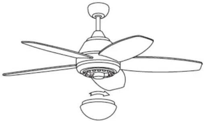
Thank you for choosing our ceiling fan. Before using this appliance and to ensure its best use, please read the instructions carefully.
The safety measures listed here reduce the risk of fire, electric shock, and injury when followed correctly. Please keep the manual in a safe place for future reference, as well as the sales receipt and box. If applicable, give these instructions to the future owner of the appliance.
Always follow basic safety instructions and hazard prevention measures when using an electrical appliance. The manufacturer will not be responsible for any damage resulting from the user's failure to follow these instructions.
LOCATION AND INSTALLATION REQUIREMENTS
MECHANIC TIPS
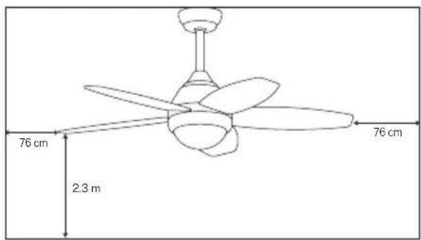
- According to safety regulations, the lowest point of the fan blade must be at least 2.3m (7 feet) from the floor.
- Please make sure the chosen location will not allow the rotating fan blades to come into contact with any objects.
- Ensure ceiling joists are sound and are large and strong enough to support the weight of the fan.
- To reduce the risk of fire, electric shock or personal injury, ensure that the fan mounting bracket is attached directly to the building structure. Do not mount to an outlet box.
- The mounting bracket must be firmly screwed to a load bearing structure, e.g. a concrete ceiling, steel structure or timber frame. If a timber frame is added, it must be securely nailed or screwed between two beams.
- To reduce risk of personal injury and property damage, do not bend or damage the downrod or the fan blades when handling or installing them. If you notice any product imperfections, please contact our after-sales service before proceeding to install the fan.
- Make sure the ceiling fan is securely fastened to the ceiling. All set screws must be checked and re-tightened where necessary before fan operation.
ELECTRICAL TIPS
- Turn off the power before performing any work on the ceiling fan and turn off the power breaker. To avoid possible electrical shock, check that the power is turned off at the fuse box or circuit breaker panel before wiring.
- The fan, mounting bracket and lighting equipment must be connected to a ground. Check that all splices are well insulated.
- Check and confirm that all connections are correct and secure. Once all electrical connections have been made, store all cables securely.
- Do not attempt to control this fan from a wall switch or remote control that is not approved by the manufacturer for use with the fan. Do not use a solid state controller. Use of a non-approved wall switch or remote control will void your warranty.
- Do not connect the ceiling fan to a dimmer switch.
When using any electrical appliance, the following basic safety precautions should always be observed.
- Please read this manual carefully before beginning installation.
- To reduce the risk of personal injury, attach the fan directly to the building support structure following these instructions and use only the material provided.
- To avoid possible electrical shock, before installing your fan, disconnect power by turning off the electrical panel power switches and associated wall switches. If it is not possible to turn off the power switches, use a warning device such as a label on the electrical panel.
- All cables must meet specifications established by local and national electrical codes and ANSI/NFPA 70. If you are not familiar with electrical installations, consult a qualified electrician.
- Do not bend the blade attachment system while installing, tilting, or cleaning blades.
- Do not insert other objects between the fan blades.
- To reduce the risk of fire, electric shock, or motor damage, do not use a solid-state speed regulator with this fan. Only use the original speed regulators.
- This appliance can be used by children aged 8 years and older and people with reduced physical, sensory or mental capabilities, or lack of experience or limited knowledge, provided they are supervised by a person responsible for their safety or who has been trained how to use it. the appliance safely.
- Children should not play with this device. They should also not carry out cleaning and maintenance tasks on the device unless they are over 8 years old and supervised. Children need to be closely supervised when using any appliance.
NOTE: The instructions and safety precautions in this manual may not cover all possible problems and situations. You should understand that both common sense and caution are essential in the installation and use of the fan.
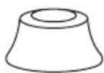
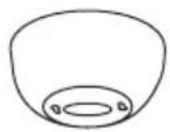
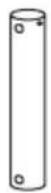
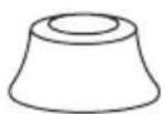
PARTS LIST
- Carefully open the packaging and remove the parts included inside.
- Place them on the floor on a rug or a piece of plastic large enough to prevent any damage.
- Check that the objects listed below are inside the packaging.
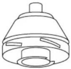
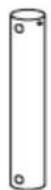
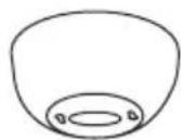
natural_image
Line drawing of a conical mechanical component with a cylindrical body and flange (no text or symbols)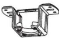
Mounting bracket
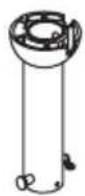
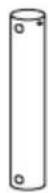
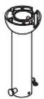
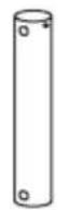
Bar Bar of
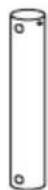
extension

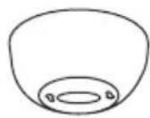
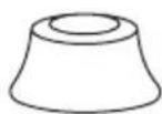
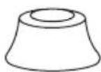
Floron Engine
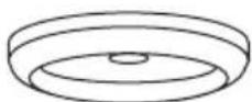
Decorative cover Decorative Decorative
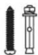
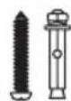
Svedids

Fixing screws
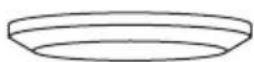
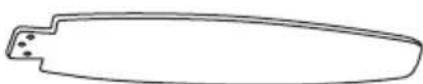
Blades Remote control Connection panel
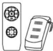
& Driver
Parts only for the model WITH LIGHT
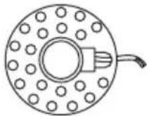
Decorative light screenLED panel
REMOTE CONTROL
- Speed control
- ** Light control button
- Turn off Botton
- Power indicator
- Timer
- Battery for remote control
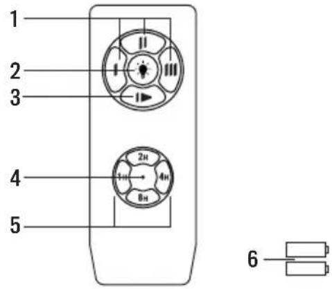
** Function only for the option with light
Warnings
- Please use this product under the correct tension. Too low voltage will result in failed operation.
- Remove the batteries from the remote control if you are not going to use it for a long time.
Note: For safety reasons and to ensure optimal operation, connect the ground wire correctly. - When installing the fan, make sure that nothing presses on the receiver antenna or other cables to prevent a short circuit.
ISSUES: When the remote control does not work, check whether:
• The fan has power.
• The fan is connected correctly.
• The battery in the remote control is charged.
- There are other remote controlled products nearby and in operation. Remote controlled products with the same frequency that are operating in proximity will interfere with each other.
INSTALLATION INSTRUCTIONS
INSTALLATION PREPARATION


• To avoid personal injury and injury, ensure that the fan is hung in a location that allows the blades to be 2.3 m or more from the floor and 76 cm from the nearest wall or obstacle.
- Make sure the mounting bracket is adequately secured to the building structure and can support the full weight of the fan.
INSTALLING THE MOUNTING BRACKET
- Check that the ceiling where you intend to mount the fan is stable and capable of safely supporting the weight of the fan.
- Do not fix the mounting bracket directly on ceilings less than 10mm to avoid the risk of the screw loosening and coming out.
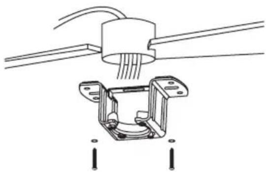
natural_image
Technical line drawing of a mechanical assembly with wires and mounting brackets (no text or symbols)Wood roof
Drill the necessary holes and then secure the mounting bracket with the wood screws and washers to the ceiling joints.
concrete roof
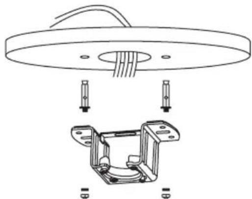
natural_image
Technical line drawing of a mechanical assembly with a circular component and bracket (no text or symbols)Drill holes with an 8mm drill bit, according to the length of the expansion screws. Next, secure the mounting bracket to the ceiling with the expansion screws.
NOTE: This fan can also be installed in a false ceiling, for this you must use fixing screws with a spring lever (not included).
- Mark the correct position of the holes and fix the ceiling support using the screws with metal anchors or screws and washers suitable for the type of ceiling chosen.
- Verify proper installation of the bracket before hanging the fan. The mounting bracket must support the entire weight of the fan.
CHOICE OF MOUNTING TYPE
Traditional assembly Angle mounting
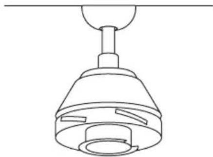
natural_image
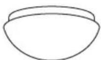
Line drawing of a ceiling lamp with a conical shade and adjustable base (no text or symbols)The traditional setup hangs from the ceiling with a rod.
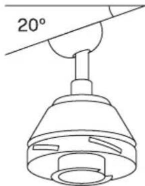
natural_image
Line drawing of a ceiling lamp with a 20° angle标注 (no text or symbols on the lamp itself)Angle mounting is recommended on sloped or vaulted ceilings.
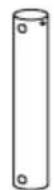
This fan can be installed on both a regular and vaulted ceiling, and can extend the hanging length with the longer hanging rod (supplied). To install the hanger bar you will need the following tools: a screwdriver, flat head screwdriver, adjustable pliers or wrench, step ladder, wire cutters, and electrical tape.
SUSPENSION BAR INSTALLATION
- If you want to extend the hanging length of your fan, remove the ball from the hanger rod and use the additional extension rod (included).
-
If you want to use the extension bar, follow the following instructions:
-
To remove the ball from the suspension rod, loosen the set screw and remove the cotter pins.
- Lower the ball and remove the locking pin.
- Take the ball out of the hanger bar and insert it into the longer hanger bar (the top of the bar has a hole for the set screw; use this to secure the bar).
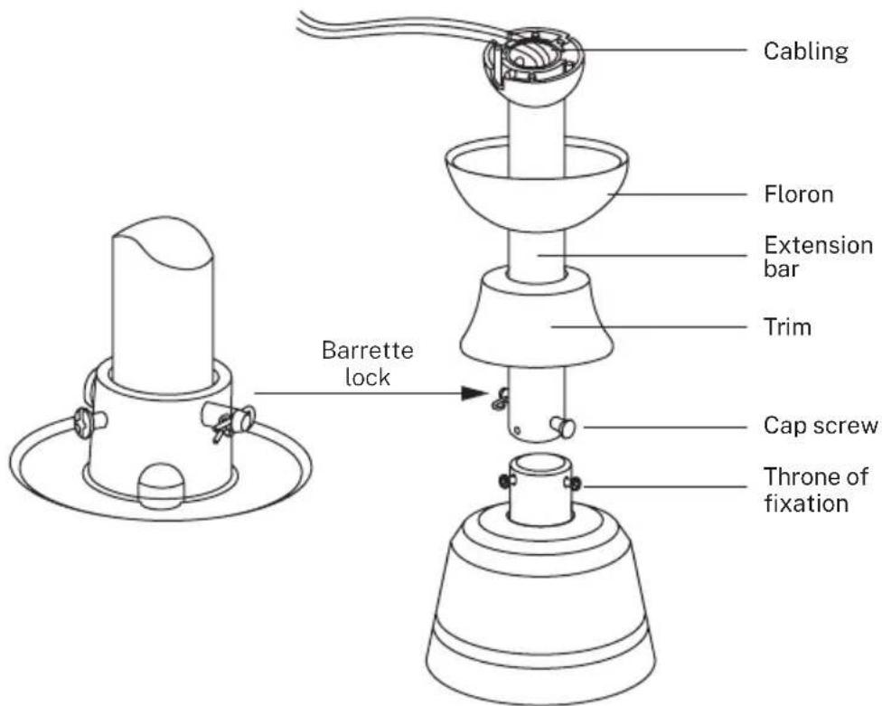
- Insert the locking pin into the end of the suspension rod and raise the ball. Make sure the locking pin is aligned with the grooves inside the ball and secure the set screw.
Advice: To make it easier to insert the wires into the bar, place some electrical tape around the wires. This will help you keep them together as you insert them into the bar.
- Loosen the mounting screws and washer from the top of the motor housing. Remove the bar pins (if you haven't already). Insert the rosette through the bar.
- Thread the cables through the bar and pull the excess cables from the top of the bar to tighten them.
- Place the bar inside the motor housing and insert the pins you removed earlier. Tighten the set screws and washers.
- Lower the canopy towards the motor housing.
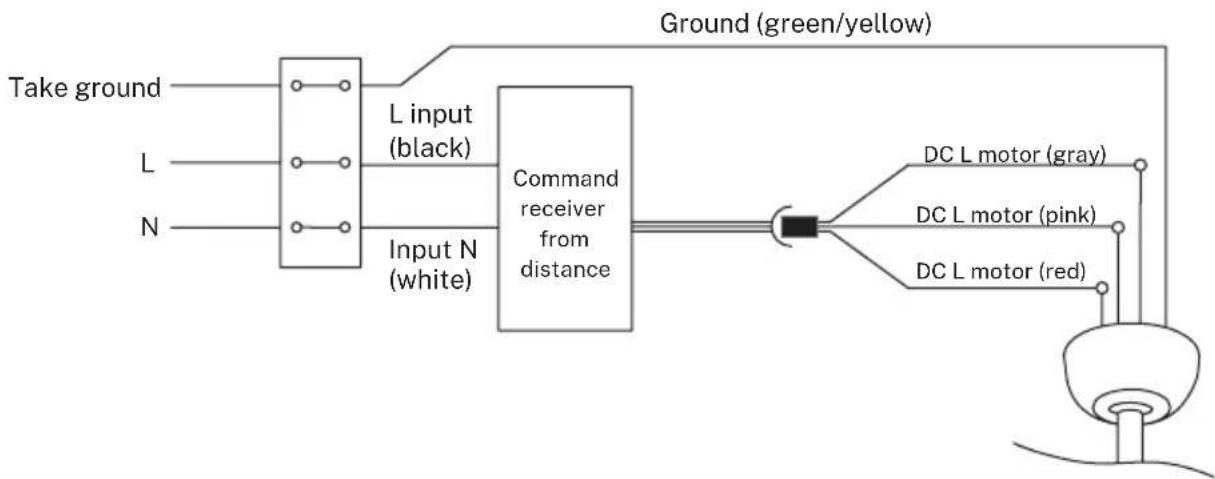
WIRING CONNECTION
Make the connection between the receiver wires and the fan motor wires following the color indications. Make sure the connection is tight.
flowchart
graph LR
    A["Take ground"] --> B["L input (black)"]
    C["L"] --> D["Command receiver from distance"]
    E["N"] --> D
    B --> D
    D --> F["DC L motor (gray)"]
    D --> G["DC L motor (pink)"]
    D --> H["DC L motor (red)"]
    I["Ground (green/yellow)"] --> F
    I --> G
    I --> H
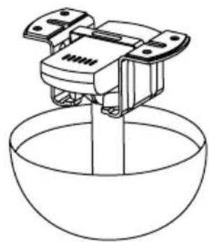
FAN SUSPENSION
- Hang the motor housing on the mounting bracket. Rotate the fan so that the notch in the ball engages the ridge of the mounting bracket.
- Place the remote control receiver into the slot of the mounting bracket as shown in the figure.
- Drive two screws in the middle position into opposite holes until there is approximately 5mm between the screw head and the edge of the mounting plate. Don't forget to place washers between the screw head and the mounting bracket.
- Slide the canopy onto the mounting bracket and align the locking slots with the two installed screws.
- Turn the finial and tighten the screws. Install the two remaining mounting screws into the other two holes in the canopy and tighten securely.
- Once the electrical installation has been checked and completed, push the canopy upwards until the ceiling support and all the connection cables are covered. Match the screws by lining up the holes in the canopy with the side holes in the bracket.
natural_image
Line drawing of a mechanical device above a bowl (no text or symbols)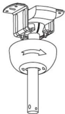
natural_image
Technical line drawing of a mechanical component with rotating arrow and shaft (no text or symbols)
natural_image
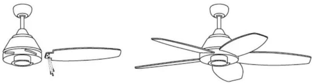
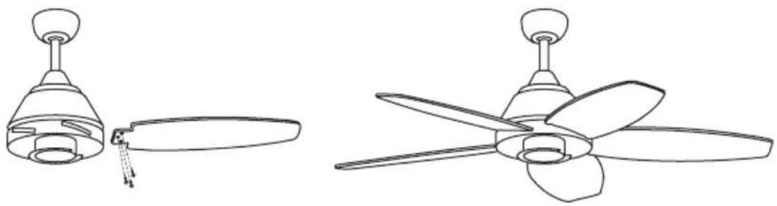
Simple line drawing of a cylindrical object with a curved top and base, no text or symbols present.BLADES ASSEMBLY

natural_image
Line drawings of a double-decker air conditioner fan and its three-blade propeller (no text or symbols)- Place the blade support and screw each blade one by one until they are completely secured. Do not overtighten the screws.
- Then align with the blade support and the assembled blades, fit the support to the fan motor, lining up the holes to be able to screw them.
- Once the blades are mounted on the fan body, screw the screws back in, making sure they are perfectly secured.
CONNECTIONS PANEL ASSEMBLY
natural_image
Line drawings of a double-decker airship with five blades and a central hub, shown from top and side views (no text or symbols)- Attach the plate to the bottom of the fan by inserting the screw heads into the holes provided. Screw in the screws and then secure them.
DECORATIVE COVER ASSEMBLY
*Only for the model WITHOUT LIGHT
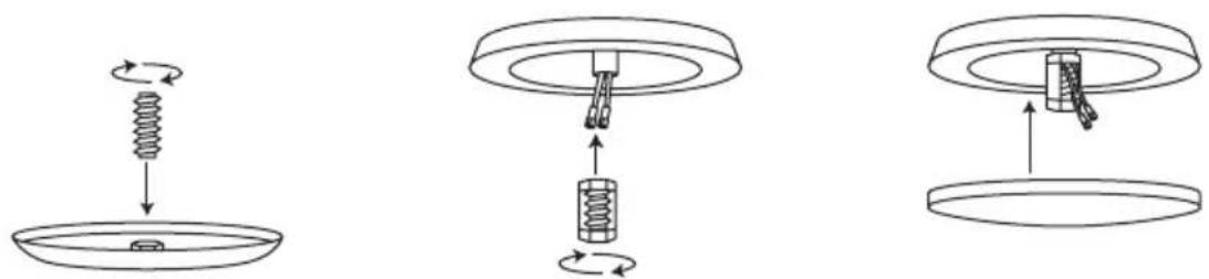
- Once the connection plate is assembled and secured, screw the decorative cover back to the connection plate using the central screw.
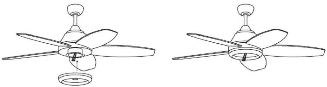
LIGHT ASSEMBLY
\*Only for the model WITHOUT LIGHT
- Connect the single pin sockets on the breakout board to those on the LED panel. The LED panel is magnetized so it attaches to the connection board by simply putting both pieces together.
natural_image
Line drawings of two identical ceiling fan designs with five blades and a central hub (no text or symbols)Note: While installing or removing the LED board, be careful not to touch the insulating tabs. Do not overtighten the screws or thread them too quickly as this could cause damage to the insulating tabs.
- Finally, place the decorative light shade by screwing it onto the LED plate.
natural_image
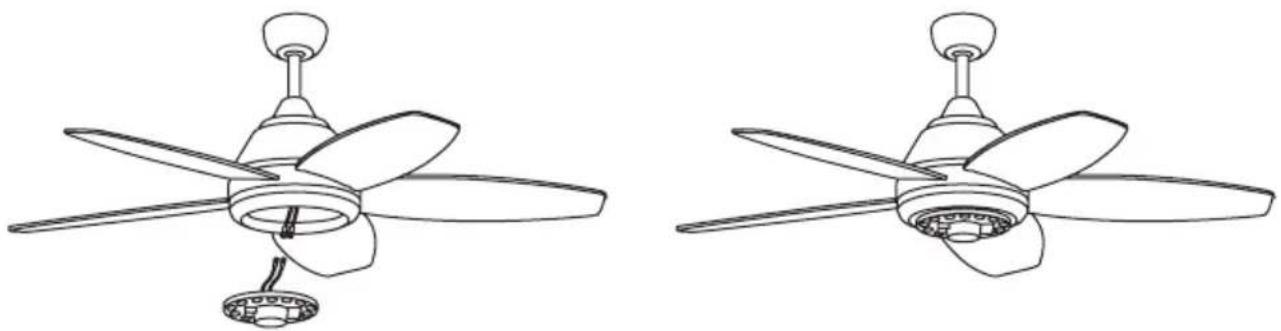
Line drawing of a five-blade propeller with central hub and fan blades (no text or symbols)CHECK INSTALLATION
- Check the correct operation of the ceiling fan, checking that no strange movement or misalignment is observed in any part of the fan.
- If you notice any type of hum/vibration, you can proceed to adjust the blades with the balancing kit.
- This kit has self-adhesive counterweights and "u" shaped clips.
- Turn off the ceiling fan.
- You can put the clip in the center of any blade and check to see if the vibration decreases.
- Turn on the fan and check. If no change is seen, turn off the fan and add another clip on another blade or use the adhesive weights.
In compliance with directives: 2012/19/eu and 2015/863/eu on the restriction of the use of dangerous substances in electric and electronic equipment as well as their waste disposal. The symbol with the crossed dustbin shown on the package indicates that the product at the end of its service life shall be collected as separate waste. Therefore, any products that have reached the end of their useful life must be given to waste disposal centres specialising in separate collection of waste electrical and electronic equipment, or given back to the retailer at the time of purchasing new similar equipment, on a one for one basis. The adequate separate collection for the subsequent start-up of the equipment sent to be recycled, treated and disposed of in an environmentally compatible way contributes to preventing possible negative effects on the environment and health and optimises the recycling and reuse of components making up the apparatus. Abusive disposal of the product by the user involves application of the administrative sanctions according to the laws.
natural_image
Line drawing of a mechanical component with a conical top and flanged base (no text or symbols)
Soporte de montaje

Barra Barra de
extensión
Florón Motor

Cubierta decorativa TapaTobodtetiva

natural_image
Technical line drawing of a mechanical assembly with no visible text or symbolsTecho de madera
natural_image
Technical line drawing of a mechanical assembly with a circular component and bracket (no text or symbols)Techo de hormigón
natural_image
Line drawing of a ceiling lamp with a conical shade and adjustable base (no text or symbols)natural_image
Line drawing of a ceiling lamp with a 20° angle标注 (no text or symbols on the lamp itself)natural_image
Line drawing of a mechanical device above a bowl (no text or symbols)
natural_image
Technical line drawing of a mechanical component with rotational arrow indicating motion (no text or symbols)
natural_image
Simple line drawing of a cylindrical object with a curved top and base, no text or symbols present.MONTAJE DE LAS ASPAS
natural_image
Line drawings of a double-decker air fan with propeller blades and a conical top (no text or symbols)natural_image
Line drawings of a three-blade propeller fan with a central hub and base, shown from different angles (no text or symbols)natural_image
Line drawing of a five-blade ceiling fan with a headlamp and base mount (no text or symbols)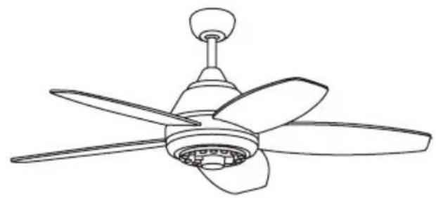
natural_image
Line drawing of a five-blade propeller with a top knob (no text or symbols)natural_image
Line drawing of a five-blade propeller with a central hub and base (no text or symbols)natural_image
Line drawing of a conical mechanical component with a cylindrical body and flange (no text or symbols)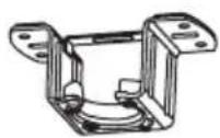
Suporte de montagem

Bar Barra de
extensão

Floron Motor
natural_image
Technical line drawing of a mechanical assembly with wires and mounting brackets (no text or symbols)Telhado de madeira
natural_image
Technical line drawing of a mechanical assembly with a circular component and bracket (no text or symbols)Telhado de concreto
natural_image
Line drawing of a ceiling lamp with a conical shade and central hub (no text or symbols)natural_image
Line drawing of a conical lamp with a 20° angle label (no text or symbols on the lamp itself)natural_image
Line drawing of a mechanical device above a bowl (no text or symbols)
natural_image
Technical line drawing of a mechanical component with rotating arrow and base (no text or symbols)
natural_image
Simple line drawing of a cylindrical object with a curved top and base, no text or symbols present.MONTAGEM DO PATCH PANEL

natural_image
Line drawings of a double-decker air conditioner fan with propeller blades and a bulb (no text or symbols)natural_image
Line drawings of a double-decker airship with propeller blades and fan base (no text or symbols)natural_image
Line drawing of a five-blade ceiling fan with a headlamp (no text or symbols)
natural_image
Line drawing of a five-blade propeller with a top knob (no text or symbols)natural_image
Line drawing of a five-blade propeller with a central hub and fan base (no text or symbols)natural_image
Line drawing of a conical mechanical component with a cylindrical base and flange (no text or symbols)
Support de montage

Barra Bar de

extension
Floron Moteur
natural_image
Technical line drawing of a mechanical assembly with no visible text or symbolsToiture en bois
natural_image
Technical line drawing of a ceiling lamp and its internal mechanical bracket assembly (no text or symbols)natural_image
Line drawing of a ceiling lamp with a conical shade and mounting bracket (no text or symbols)natural_image
Line drawing of a ceiling lamp with a 20° angle标注 (no text or symbols on the lamp itself)natural_image
Line drawing of a mechanical device above a bowl (no text or symbols)
natural_image
Technical line drawing of a mechanical component with rotational arrow indicating motion (no text or symbols)
natural_image
Simple line drawing of a cylindrical object with a curved top and base, no text or symbols present.INSTALLATION DE LA LAME

natural_image
Line drawings of a double-decker air conditioner fan and its three-blade propeller (no text or symbols)natural_image
Line drawings of a double-decker airship with three blades and a central hub, shown from top and side views (no text or symbols)natural_image
Three technical diagrams showing mechanical assembly steps: spring, spring inside a bowl, and mechanical assembly with a handle (no text or labels)natural_image
Line drawings of two identical propeller fan designs with blades and a base (no text or symbols)natural_image
Line drawing of a five-blade ceiling fan with propeller and bulb (no text or symbols)VÉRIFIER L'INSTALLATION
natural_image
Line drawing of a conical mechanical component with a cylindrical body and flange (no text or symbols)
Staffa di fissaggio

Sbarra Barra di
estensione

Fiorino Motore
natural_image
Technical line drawing of a mechanical assembly with no visible text or symbolsTetto in legno
natural_image
Technical line drawing of a mechanical assembly with a circular component and bracket (no text or symbols)natural_image
Line drawing of a ceiling lamp with a conical shade and central hub (no text or symbols)natural_image
Line drawing of a funnel-shaped lamp with a 20° angle label (no text or symbols on the lamp itself)natural_image
Line drawing of a mechanical device above a bowl (no text or symbols)
natural_image
Technical line drawing of a mechanical component with rotational arrow indicating motion (no text or symbols)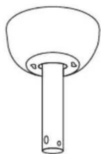
natural_image
Simple line drawing of a cylindrical object with a curved top and base, no text or symbols present.natural_image
Line drawings of a double-decker air conditioner fan and its three-blade propeller (no text or symbols)natural_image
Line drawings of a double-decker airship with five blades and a central hub, shown from top and side views (no text or symbols)natural_image
Three technical diagrams showing mechanical assembly steps: spring, spring inside a bowl, and internal spring assembly with a handle (no text or labels)natural_image
Line drawings of a double-decker airship with five blades and a central hub (no text or symbols)natural_image
Line drawing of a five-blade ceiling fan with a central hub and propeller (no text or symbols)natural_image
Line drawing of a conical mechanical component with a cylindrical base and flange (no text or symbols)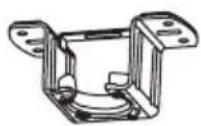
Montagehalterung
Bar Ein Riegel
Verlängerung

Floron Motor
natural_image
Technical line drawing of a mechanical assembly with wires and mounting brackets (no text or symbols)Holzdach
natural_image
Technical line drawing of a mechanical assembly with mounting holes and a bracket (no text or symbols)Betondach
natural_image
Line drawing of a ceiling lamp with a conical shade and handle (no text or symbols)natural_image
Line drawing of a ceiling lamp with a 20° angle标注 (no text or symbols on the lamp itself)natural_image
Line drawings of a double-decker air fan with propeller blades and a conical top (no text or symbols)natural_image
Line drawings of a double-decker airship with propeller blades and fan base (no text or symbols)natural_image
Three technical diagrams showing mechanical assembly steps: spring rotation, spring assembly, and final assembly (no text or labels)natural_image
Line drawings of two different types of propeller blades, shown from top and side views (no text or symbols)natural_image
Line drawing of a five-blade propeller with a central hub and fan base (no text or symbols)ÜBERPRÜFEN SIE DIE INSTALLATION
natural_image
Line drawing of a conical mechanical component with a cylindrical body and flange (no text or symbols)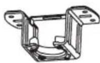
Montagebeugel

Bar Barra di
estensione

Floron Motor
INSTALLATIE INSTRUCTIES
INSTALLATIE VOORBEREIDING

natural_image
Technical line drawing of a mechanical assembly with no visible text or symbolsHouten dak
natural_image
Technical line drawing of a mechanical assembly with a circular component and bracket (no text or symbols)Betonnen dak
natural_image
Line drawing of a ceiling lamp with a conical shade and central hub (no text or symbols)natural_image
Line drawing of a conical lamp with a 20° angle label (no text or symbols on the lamp itself)natural_image
Line drawing of a mechanical device above a bowl (no text or symbols)
natural_image
Technical line drawing of a mechanical component with rotational arrow indicating motion (no text or symbols)
natural_image
Simple line drawing of a cylindrical object with a curved top and base, no text or symbols present.INSTALLATIE VAN HET MES
natural_image
Line drawings of a double-decker air conditioner fan and its three-blade propeller (no text or symbols)natural_image
Line drawings of a five-blade propeller with a central hub and base, shown from two different angles (no text or symbols)natural_image
Three technical diagrams showing mechanical assembly steps: spring, spring inside a bowl, and internal spring assembly with a handle (no text or labels)natural_image
Line drawing of a five-blade ceiling fan with a propeller and base mount (no text or symbols)
natural_image
Line drawing of a five-blade propeller with a top knob (no text or symbols)natural_image
Line drawing of a five-blade ceiling fan with visible blades and central hub (no text or symbols)CONTROLEER DE INSTALLATIE
natural_image
Line drawing of a mechanical component with a conical top and flanged base (no text or symbols)
Uchwyt montażowy

Bar Pasek

rozszerzenie
Floron Silnik
Ozdobna okładka
Śruby

Śruby
mocujące
natural_image
Technical line drawing of a mechanical assembly with no visible text or symbolsDach drewniany
natural_image
Technical line drawing of a mechanical assembly with a circular component and bracket (no text or symbols)betonowy dach
natural_image
Line drawing of a ceiling lamp with a conical shade and adjustable base (no text or symbols)natural_image
Line drawing of a ceiling lamp with a 20° angle标注 (no text or symbols on the lamp itself)natural_image
Line drawing of a mechanical device above a bowl (no text or symbols)
natural_image
Technical line drawing of a mechanical component with rotational arrow indicating motion (no text or symbols)
natural_image
Simple line drawing of a cylindrical object with a curved top and base, no text or symbols present.INSTALACJA OSTRZA