
WIND TUBE - Fan Create - Free user manual and instructions
Find the device manual for free WIND TUBE Create in PDF.

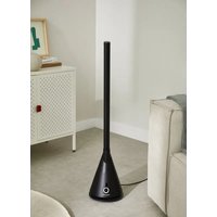
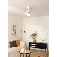
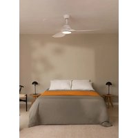
| Product type | Ceiling fan |
| Brand | Create |
| Model | WIND TUBE |
| Power supply | 120 V, 60 Hz (AC current) |
| Motor | DC motor, 3 speeds |
| Controls | Infrared remote control with 2 AAA batteries |
| Functions | On/off, speed control, timer, reverse function (summer/winter), sound off |
| Timer | Programmable automatic shut-off |
| Minimum ground clearance | 2.3 meters |
| Wall clearance | 76 cm from any wall or obstacle |
| Installation | On ceiling, on load-bearing structure (wood or concrete) |
| Weight | Approximately 6 kg (estimate) |
| Materials | Metal and plastic |
| Maintenance | Clean with a soft dry cloth; do not use abrasive products |
| Safety | Do not use with a dimmer; cut off power before installation; do not bend the blades |
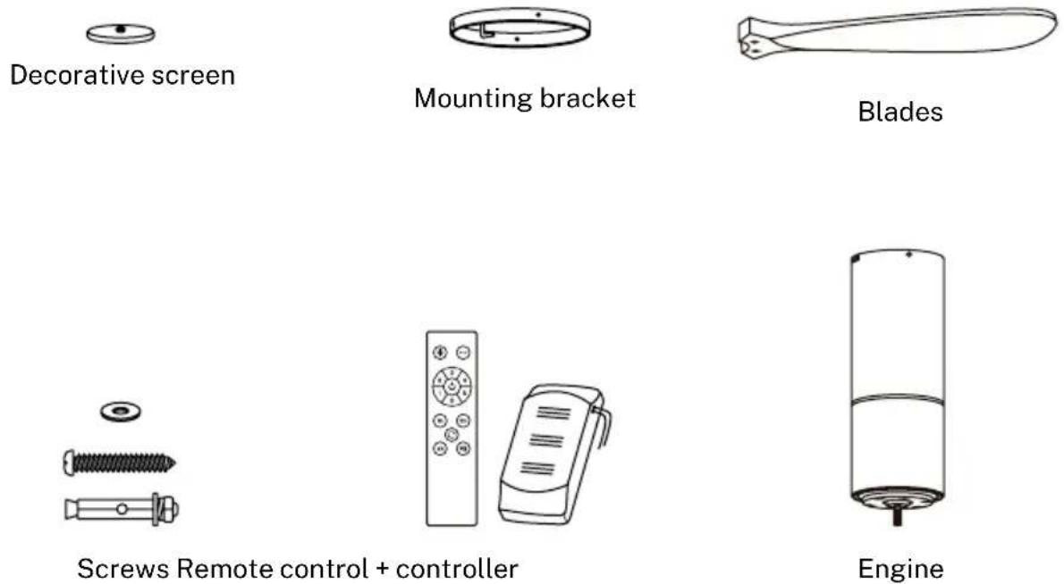
| Spare parts | Blades, mounting bracket, receiver, remote control, decorative cap |
| Warranty | Refer to the user manual for details |
Frequently Asked Questions - WIND TUBE Create
User questions about WIND TUBE Create
0 question about this device. Answer the ones you know or ask your own.
Ask a new question about this device
Download the instructions for your Fan in PDF format for free! Find your manual WIND TUBE - Create and take your electronic device back in hand. On this page are published all the documents necessary for the use of your device. WIND TUBE by Create.
USER MANUAL WIND TUBE Create
natural_image
Line drawing of a three-blade propeller with a cylindrical shaft and mounting base (no text or symbols)Wind Tube
User manual | Manual de instrucciones
CREATE CREATE CREATE ATE CREATE CREATE CRE CREATE CREATE CREATE ATE CREATE CREATE CRE CREATE CREATE CREATE ATE CREATE CREATE CRE CREATE CREATE CREATE ATE CREATE CREATE CRE CREATE CREATE CREATE ATE CREATE CREATE CRE CREATE CREATE CREATE ATE CREATE CREATE CRE CREATE CREATE CREATE ATE CREATE CREATE CRE CREATE CREATE CREATE ATE CREATE CREATE CRE CREATE CREATE CREATE ATE CREATE CREATE CRE CREATE CREATE CREATE ATE CREATE CREATE CRE CREATE CREATE CREATE ATE CREATE CREATE CRE CREATE CREATE CRE CREATE CREATE CRE ATE CREATE CREATE CRE CREATE CREATE CRE CREATE CREATE CRE
CREATE CREATE CREATE ATE CREATE CREATE CRE CREATE CREATE CREATE ATE CREATE CREATE CRE CREATE CREATE CREATE ATE CREATE CREATE CRE CREATE CREATE CREATE ATE CREATE CREATE CRE CREATE CREATE CREATE ATE CREATE CREATE CRE CREATE CREATE CREATE ATE CREATE CREATE CRE CREATE CREATE CREATE ATE CREATE CREATE CRE CREATE CREATE CREATE ATE CREATE CREATE CRE CREATE CREATE CREATE ATE CREATE CREATE CRE CREATE CREATE CREATE ATE CREATE CREATE CRE CREATE CREATE CREATE ATE CREATE CREATE CRE CREATE CREATE CRE CREATE CREATE CRE CREATE CREATE CRE
INDEX
ENGLISH
List of parts 6
Security instructions 7
Installation instructions 8
Installation preparation 8
Mechanic tips 8
Electrical tips 8
Fixing the mounting bracket 9
Receiver connection 9
Wiring connection 9
Fixing the engine to the ceiling support 10
Assembly of the blade 10
Insert decorative cap 10
Remote control 11
Portugês
Lista de peças 18
Thank you for choosing our ceiling fan. Before using the appliance, and to ensure the best use, read these instructions carefully.
The safety precautions contained in this document reduce the risk of death, injury and electric shock when followed correctly. Please keep the manual, sales receipt and packaging in a safe place for future reference. If applicable, pass these instructions on to the next owner of the appliance.
Always follow basic safety precautions and accident prevention measures when using an electrical appliance. We assume no responsibility for the customer's failure to comply with these requirements.
LIST OF PARTS
Carefully open the packaging and remove all included items. Place them on a rug or a large piece of plastic to prevent any damage. Check that all items listed below have been included.
When using any electrical appliance, basic safety precautions should always be observed.
- Please read this entire manual carefully before beginning installation.
- Save these instructions.
- Only use original spare parts.
- To reduce the risk of personal injury, attach the fan directly to the building support structure in accordance with these instructions and use only the supplied hardware.
- To avoid possible electrical shock, before installing your fan, disconnect power by turning off the circuit breakers at the outlet box and the associated wall switch location. If the breakers cannot be locked in the off position, securely attach a prominent warning device, such as a tag, to the service panel.
- All wiring used must be in accordance with national and local electrical codes and ANSI/NFPA 70. If you are not familiar with wiring, contact a qualified electrician.
- To reduce the risk of personal injury, do not bend the blade retaining system when installing, balancing, or cleaning the fan.
- Never insert foreign objects between the rotating fan blades.
• To reduce the risk of fire, electric shock, or motor damage, do not use a solid-state speed control with this fan. Use only original speed controls. - This appliance can be used by children aged 8 years and older and persons with reduced physical, sensory or mental capabilities or lack of experience and knowledge if they have been given supervision or instruction concerning use of the appliance in a safe way and understand the hazards involved.
- Children should not play with the device.
- Children should not clean or maintain the appliance unless they are over 8 years of age and supervised.
- Close supervision is necessary when any appliance is used by or near children.
ADVICE: The important safety precautions and instructions in this manual are not intended to cover all conditions and situations that may occur. When installing and operating this fan, use common sense and caution.
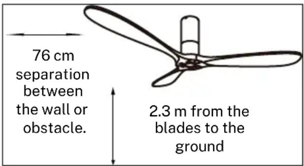
INSTALLATION PREPARATION
- To avoid personal injury and damage, make sure the blade hanging location leaves 2.3 m of ground clearance and 76 cm of any wall or obstacle.
MECHANIC TIPS
- In accordance with safety regulations, the lowest point of the fan blades must be at least 2.3 meters from the ground.
- Make sure the chosen location does not allow the rotating blades to come into contact with any objects.
- Check that the ceiling joists are secure and large and strong enough to support the weight of the fan.
- To reduce the risk of fire, electric shock, or personal injury, ensure the fan mounting bracket is attached directly to the building structure. DO NOT mount in a distribution box.
- The mounting bracket must be securely bolted to a supporting structure, such as a concrete roof, steel structure, or wooden frame. If a wooden frame is added, it should be nailed or screwed securely between two joists.
- To reduce the risk of personal injury and property damage, do not bend or damage the vertical rod or fan blades when handling or installing the fan. If you detect any damage to the product, contact our after-sales service before proceeding with the installation of the fan.
- Make sure the fan is securely attached to the ceiling. All fixing screws should be checked and retightened whenever necessary before starting the fan.
ELECTRICAL TIPS
- Turn off the power before performing any work on the ceiling fan and turn off the power breaker. To avoid possible electrical shock, check that the power is turned off at the fuse box or circuit breaker panel before wiring.
- The fan, mounting bracket and lighting equipment must be connected to the ground. Check that all splices are well insulated.
- Check and confirm that all connections are correct and secure. Once all electrical connections have been made, store all cables securely.
- Do not attempt to control this fan from a wall switch or remote control that is not approved by the manufacturer for use with the fan. DO NOT use a solid state controller. Use of a non-approved wall switch or remote control will void your warranty.
- Do not connect the ceiling fan to a dimmer switch.
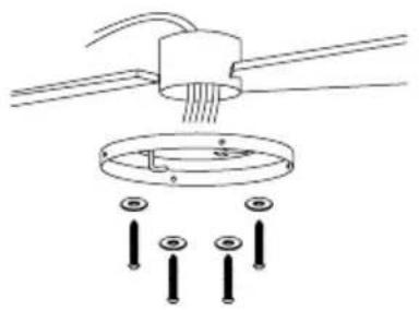
FIXING THE MOUNTING BRACKET
The mounting bracket must be securely mounted and able to safely support at least the weight of the fan. Do not attach the mounting bracket directly to ceilings less than 10mm to avoid the risk of the screw loosening and coming out.
natural_image
Diagram of a ceiling lamp installation with screw base and mounting holes (no text or labels)Wood roof
Secure the mounting bracket with the wood screws and washers to the ceiling joints. concrete roof
natural_image
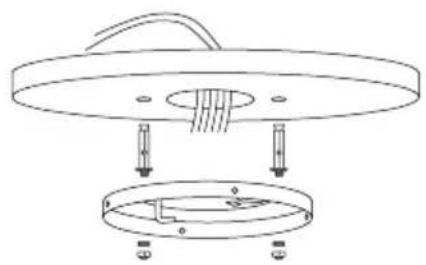
Technical line drawing of a mechanical assembly with two circular components and mounting holes (no text or symbols)Drill holes with an 8mm drill bit, according to the length of the expansion screws. Next, secure the mounting bracket to the ceiling with the expansion screws.
NOTE: This fan can also be installed in a false ceiling, for this you must use fixing screws with a spring lever (not included).
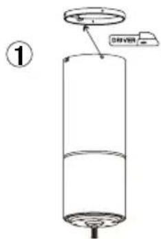
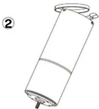
RECEIVER CONNECTION
Connect the motor to the bracket hook and then connect the wiring.
natural_image
Line drawing of a cylindrical mechanical component with a flanged top and base, labeled with number 2 (no text or symbols on the object itself)WIRING CONNECTION
Make the connection between the receiver wires and the fan motor wires following the color indications. Make sure the connection is tight.
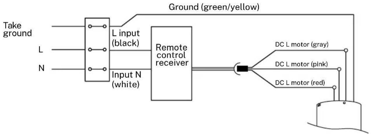
flowchart
graph LR
    A["Take ground"] --> B["L input (black)"]
    C["L"] --> B
    D["N"] --> E["Input N (white)"]
    B --> F["Remote control receiver"]
    E --> F
    F --> G["DC L motor (gray)"]
    F --> H["DC L motor (pink)"]
    F --> I["DC L motor (red)"]
    G --> J["Ground (green/yellow)"]
    H --> J
    I --> J
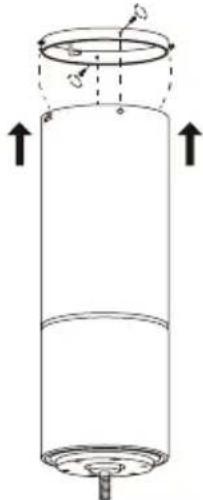
FIXING THE ENGINE TO THE CEILING SUPPORT
- Once the cables are connected and the receiver is placed inside the motor, carefully unhook the motor body and fit it into the ceiling support, securing it by making a small turn to align the screw holes.
- Once the motor is secured to the bracket, install the two screws to completely secure the motor to the ceiling bracket and secure the four screws again.
- NOTE: Check that everything is securely fastened, that the screws are tight and make sure that no cables have been pinched when fitting the motor to the bracket.
natural_image
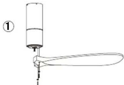
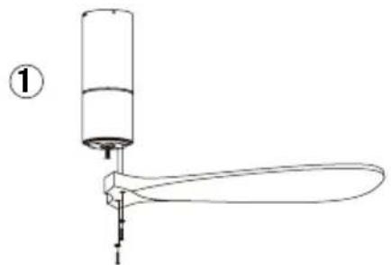
Diagram of a cylindrical container with internal structure and upward arrows indicating flow or movement (no text or symbols)ASSEMBLY OF THE BLADE

natural_image
Simple line drawing of a mechanical device with a cylindrical component and a curved handle, labeled with number 1 (no text or symbols on the diagram itself)
natural_image
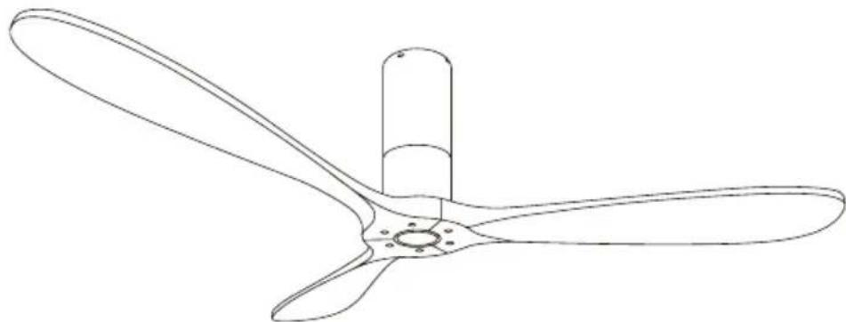
Line drawing of a propeller with three blades and a cylindrical shaft (no text or symbols)Place the washers on the blade screws. Align the blade holes with the motor screw holes and secure them to the aligned holes. Repeat this process with the remaining blades.
INSERT DECORATIVE CAP
natural_image
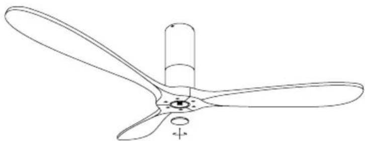
Line drawing of a three-blade propeller with a cylindrical shaft and mounting base (no text or symbols)Align the decorative cap with the threads on the motor and tighten clockwise.
natural_image
Line drawing of a three-blade propeller with a cylindrical shaft and mounting base (no text or symbols)Now your fan will be properly installed so you can reconnect the power to enjoy your new ceiling fan.
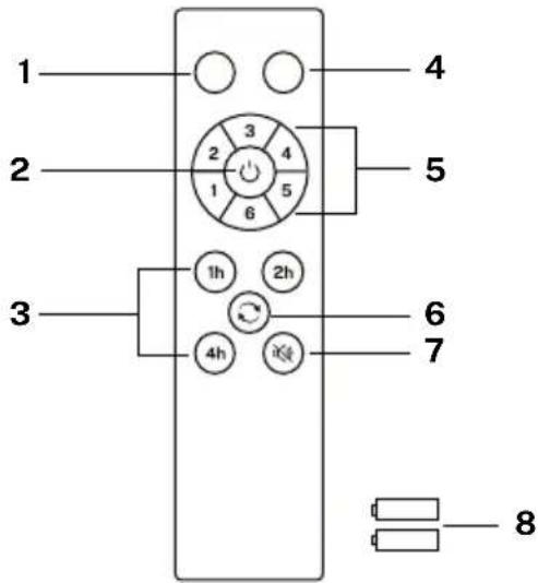
- Functionless
- ON/OFF button
- Timer
- Functionless
- Fan intensity control
- reverse function
- Sound off button
- Batteries (2 x AAA)
Controller pairing
- Turn off the main light switch in the room where you have installed your fan for at least 10 seconds.
- Turn the switch on and you will hear a beep, within 3 seconds, press and hold the on/off button until you hear a beep.
- If the pairing process is unsuccessful, repeat the above steps again after turning off the wall switch for at least 1 minute.

ON OFF
Turn the fan on or off completely, regardless whether the light is on or not.

FAN INTENSITY
Increases or decreases the rotation speed of the fan blades.

TIMER
Schedule automatic shutdown by choosing from the available options.

REVERSE FUNCTION
Changes the direction of rotation of the blades fan. The winter function (turn to the right) pushes the hot air accumulated in the ceiling downwards and the summer function (turn to the left) generates a breeze that cools the environment.

DISABLE SOUND
By pressing the sound off button you can silence the sounds that the fan makes when you press any key on the remote control.
In compliance with the directives: 2012/19/EU and 2015/863/EU on the restriction of the use of hazardous substances in electrical and electronic equipment, as well as their waste disposal. The crossed rubbish bin symbol shown on the packaging indicates that the product at the end of its useful life will be collected as separate waste. Therefore, any product that has reached the end of its useful life should be delivered to waste disposal centers specialized in the separate collection of waste electrical and electronic equipment, or returned to the retailer when purchasing similar new equipment, in one for A base. Appropriate separate collection for subsequent commissioning of equipment sent for recycling, treatment and disposal in an environmentally compatible manner contributes to preventing potential negative effects on the environment and health and optimizes the recycling and reuse of the components that make up the device. Abusive disposal of the product by the user implies the application of administrative sanctions in accordance with the laws.
natural_image
Diagram of a ceiling-mounted electrical socket with three screws and a circular housing, no text or symbols presentTecho de madera
natural_image
Technical line drawing of a mechanical assembly with two circular components and mounting holes (no text or symbols)Techo de hormigón
natural_image
Line drawing of a cylindrical mechanical component with a flanged top and base, labeled with number 2 (no text or symbols on the object itself)natural_image
Diagram of a cylindrical container with internal structure and upward arrows indicating flow or movement (no text or symbols)MONTAJE DE LAS ASPAS
natural_image
Simple line drawing of a mechanical device with a cylindrical component and a curved handle, labeled with number 1 (no text or symbols on the diagram itself)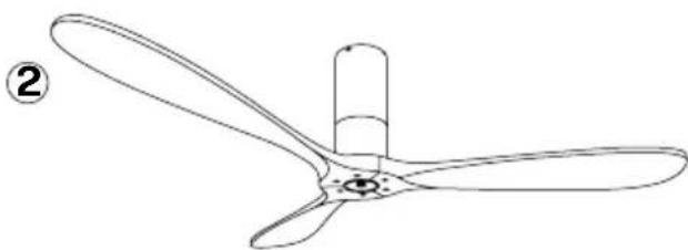
natural_image
Line drawing of a propeller with three blades and a cylindrical shaft (no text or symbols)natural_image
Line drawing of a three-blade propeller with a cylindrical shaft and mounting base (no text or symbols)natural_image
Line drawing of a three-blade propeller with a cylindrical shaft and mounting base (no text or symbols)natural_image
Diagram of a ceiling-mounted electrical socket with three screws and a circular housing, no text or symbols presentTelhado de madeira
natural_image
Technical line drawing of a mechanical assembly with two circular components and mounting holes (no text or symbols)telhado de concreto
natural_image
Line drawing of a cylindrical mechanical component with a flanged top and base, labeled with number 2 (no text or symbols on the object itself)CONEXÃO DE FIAÇÃO
natural_image
Diagram of a cylindrical container with internal structure and upward arrows indicating flow or movement (no text or symbols)MONTAGEM DA LÂMINA

natural_image
Simple line drawing of a propeller with a handle and base, labeled with number 1 (no text or symbols on the diagram itself)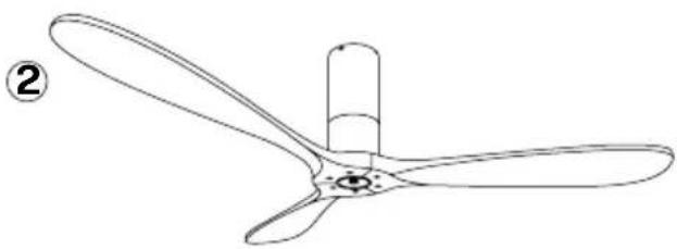
natural_image
Line drawing of a propeller with three blades and a cylindrical shaft (no text or symbols)natural_image
Line drawing of a three-blade propeller with a cylindrical shaft and mounting base (no text or symbols)natural_image
Line drawing of a three-blade propeller with a cylindrical shaft and mounting base (no text or symbols)natural_image
Diagram of a ceiling lamp installation with screw base and mounting holes (no text or labels)Toiture en bois
natural_image
Technical line drawing of a mechanical assembly with two circular components and mounting holes (no text or symbols)natural_image
Line drawing of a cylindrical mechanical component with a flanged top and base, labeled with number 2 (no text or symbols on the object itself)CONNEXION DU CÂBLAGE
natural_image
Diagram of a cylindrical container with internal structure and upward arrows indicating flow or movement (no text or symbols)ASSEMBLAGE DE LA LAME

natural_image
Simple line drawing of a mechanical device with a cylindrical component and a curved handle, labeled with number 1 (no text or symbols on the diagram itself)
natural_image
Line drawing of a propeller with three blades and a cylindrical shaft (no text or symbols)natural_image
Line drawing of a three-blade propeller with a cylindrical shaft and mounting base (no text or symbols)natural_image
Line drawing of a three-blade propeller with a cylindrical shaft and mounting base (no text or symbols)natural_image
Diagram of a ceiling fixture with three screws and a circular base, showing internal components and mounting holes (no text or labels)Tetto in legno
natural_image
Technical line drawing of a mechanical assembly with two circular components and mounting holes (no text or symbols)natural_image
Line drawing of a cylindrical mechanical component with a flanged top and base, labeled with number 2 (no text or symbols on the object itself)natural_image
Diagram of a cylindrical container with internal structure and upward arrows indicating flow or movement (no text or symbols)natural_image
Simple line drawing of a mechanical device with a cylindrical component and a curved handle, labeled with number 1 (no text or symbols on the diagram itself)
natural_image
Line drawing of a propeller with three blades and a cylindrical shaft (no text or symbols)natural_image
Line drawing of a three-blade propeller with a cylindrical shaft and mounting base (no text or symbols)natural_image
Line drawing of a three-blade propeller with a cylindrical shaft and mounting base (no text or symbols)natural_image
Technical diagram of a ceiling fixture with screw holes and a central component (no text or labels)Holzdach
natural_image
Technical line drawing of a mechanical assembly with two views (top and bottom) showing internal components and mounting holes (no text or symbols)Betondach
natural_image
Line drawing of a cylindrical mechanical component with a flanged top and base (no text or symbols)natural_image
Simple line drawing of a cylindrical container with an upward arrow indicating flow or movement (no text or symbols)MONTAGE DER KLINGE

natural_image
Simple line drawing of a propeller with a handle and base, labeled with number 1 (no text or symbols on the diagram itself)
natural_image
Line drawing of a propeller with three blades and a cylindrical shaft (no text or symbols)natural_image
Line drawing of a three-blade propeller with a cylindrical shaft and mounting base (no text or symbols)natural_image
Line drawing of a three-blade propeller with a cylindrical shaft and mounting base (no text or symbols)natural_image
Diagram of a ceiling fixture with screw holes and a central circular component (no text or symbols)Houten dak
natural_image
Technical line drawing of a mechanical assembly with two circular components and mounting holes (no text or symbols)Betonnen dak
natural_image
Line drawing of a cylindrical mechanical component with a flanged top and base, labeled with number 2 (no text or symbols on the object itself)BEDRADINGSVERBINDING
natural_image
Diagram of a cylindrical container with internal structure and upward arrows indicating flow or movement (no text or symbols)MONTAGE VAN HET MES
natural_image
Simple line drawing of a propeller with a handle and base, labeled with number 1 (no text or symbols on the diagram itself)
natural_image
Line drawing of a propeller with three blades and a cylindrical shaft (no text or symbols)natural_image
Line drawing of a three-blade propeller with a cylindrical shaft and mounting base (no text or symbols)natural_image
Line drawing of a three-blade propeller or fan with a cylindrical shaft and mounting base (no text or symbols)natural_image
Diagram of a ceiling lamp installation with screw base and mounting holes (no text or labels)Dach drewniany
natural_image
Technical line drawing of a mechanical assembly with two circular components and mounting holes (no text or symbols)betonowy dach
natural_image
Simple line drawing of a cylindrical object with a handle and base, labeled with number 2 (no text or symbols on the object itself)natural_image
Diagram of a cylindrical container with internal structure and upward arrows indicating flow or movement (no text or symbols)MONTAŻ OSTRZA

natural_image
Simple line drawing of a propeller with a handle and base, labeled with number 1 (no text or symbols on the diagram itself)
natural_image
Line drawing of a propeller with three blades and a cylindrical shaft (no text or symbols)natural_image
Line drawing of a three-blade propeller with a cylindrical shaft and mounting base (no text or symbols)natural_image
Line drawing of a three-blade propeller with a cylindrical shaft and mounting base (no text or symbols)INTENSYWNOŚĆ WENTYLATORA


- Wind Tube
- INDEX
- ENGLISH
- Portugês
- LIST OF PARTS
- INSTALLATION PREPARATION
- MECHANIC TIPS
- ELECTRICAL TIPS
- FIXING THE MOUNTING BRACKET
- RECEIVER CONNECTION
- WIRING CONNECTION
- FIXING THE ENGINE TO THE CEILING SUPPORT
- ASSEMBLY OF THE BLADE
- INSERT DECORATIVE CAP
- Controller pairing
- ON OFF
- FAN INTENSITY
- TIMER
- REVERSE FUNCTION
- DISABLE SOUND
- MONTAJE DE LAS ASPAS
- CONEXÃO DE FIAÇÃO
- MONTAGEM DA LÂMINA
- CONNEXION DU CÂBLAGE
- ASSEMBLAGE DE LA LAME
- MONTAGE DER KLINGE
- BEDRADINGSVERBINDING
- MONTAGE VAN HET MES
- MONTAŻ OSTRZA
- INTENSYWNOŚĆ WENTYLATORA
Brand : Create
Model : WIND TUBE
Category : Fan