
AIR TRIPOD RETRO - Fan Create - Free user manual and instructions
Find the device manual for free AIR TRIPOD RETRO Create in PDF.

| Product Type | Pedestal fan with tripod |
| Brand | Create |
| Model | AIR TRIPOD RETRO |
| Number of Speeds | 3 (low, medium, high) |
| Oscillation | Yes, with oscillation button |
| Adjustable Height | Yes, by loosening the screw |
| Blade Material | Plastic |
| Tripod Material | Wood and metal |
| Protection Grid | Yes, front and rear |
| Power Supply | Mains, 220-240 V (estimate) |
| Power | Approx. 35-50 W (estimate) |
| Cable Length | Approx. 1.5 m (estimate) |
| Weight | Approx. 3 kg (estimate) |
| Package Dimensions | Not specified, estimate about 60 x 30 x 30 cm |
| Intended Use | Indoor only |
| Care and Cleaning | Unplug, clean with a damp cloth and mild detergent; do not immerse |
| Safety | Do not insert objects, keep out of reach of children, do not use if damaged |
| Included Spare Parts | Screws, nuts, bolts, springs, base links (see manual) |
| Warranty | Not specified, keep the warranty card |
Frequently Asked Questions - AIR TRIPOD RETRO Create
User questions about AIR TRIPOD RETRO Create
0 question about this device. Answer the ones you know or ask your own.
Ask a new question about this device
Download the instructions for your Fan in PDF format for free! Find your manual AIR TRIPOD RETRO - Create and take your electronic device back in hand. On this page are published all the documents necessary for the use of your device. AIR TRIPOD RETRO by Create.
USER MANUAL AIR TRIPOD RETRO Create
natural_image
Line drawing of a simple fan with radial blades mounted on a tripod stand (no text or symbols)STAND FAN VENTILADOR DE PIE
USER MANUAL
CREATE CREATE CREATE ATE CREATE CREATE CRE CREATE CREATE CREATE ATE CREATE CREATE CRE CREATE CREATE CREATE ATE CREATE CREATE CRE CREATE CREATE CREATE ATE CREATE CREATE CRE CREATE CREATE CREATE ATE CREATE CREATE CRE CREATE CREATE CREATE ATE CREATE CREATE CRE CREATE CREATE CREATE ATE CREATE CREATE CRE CREATE CREATE CREATE ATE CREATE CREATE CRE CREATE CREATE CREATE ATE CREATE CREATE CRE CREATE CREATE CREATE ATE CREATE CREATE CRE CREATE CREATE CREATE ATE CREATE CREATE CRE CREATE CREATE CRE CREATE CREATE CRE ATE CREATE CRE
CREATE CREATE CREATE ATE CREATE CREATE CRE CREATE CREATE CREATE ATE CREATE CREATE CRE CREATE CREATE CREATE ATE CREATE CREATE CRE CREATE CREATE CREATE ATE CREATE CREATE CRE CREATE CREATE CREATE ATE CREATE CREATE CRE CREATE CREATE CREATE CREATE CREATE CREATE CREATE CREATE CREATE CREATE CREATE CREATE CREATE CREATE CREATE CREATE CREATE CREATE CREATE CREATE CREATE CREATE CREATE CREATE CREATE CREATE CREATE CREATE CREATE CREATE CREATE CREATE CREATE CREATE CREATE CREATE CREATE CREATE CREATE CREATE CREATE CREATE CREATE CREATE CREATE CREATE CREATE CRE
INDEX
ENGLISH
Important safeguards 6
Parts list 7
Also included 7
Blade and grill assembly 9
Fan head assembly 10
How to use the fan 10
Cleaning 10
PORTUGUÊS
Importantes salvaguardas 16
Lista de peças 17
Também incluído 17
Configurando o ventilador 18
Thank you for choosing our fan. Before using the appliance, and to ensure the best use, carefully read these instructions.
The safety precautions enclosed herein reduce the risk of death, injury and electrical shock when correctly adhered to. Keep the manual in a safe place for future reference, along with the completed warranty card, purchase receipt and package. If applicable, pass these instructions on to the next owner of the appliance. Always follow basic safety precautions and accident prevention measures when using an electrical appliance. We assume no liability for customer failing to comply with these requirements.
IMPORTANT SAFEGUARDS
When using any electrical appliance, basic safety precautions should always be observed.
- Please ensure that the voltage of the fan corresponds to the mains voltage.
- Use the fan only for the purposes defined in the user guide.
- Never insert your fingers, pencils or other objects through the fan cage during operation.
- Switch the fan off before moving or cleaning.
- The fan should be set up on a stable and level surface to avoid it being knocked over.
- Do not expose the fan to excessive heat or humidity, as this can cause damage to the electrical components.
- Do not immerse in any form of liquid.
- It is not advisable to expose people, in particular babies and the elderly, to a continuous stream of cold air.
• The fan should be kept out of reach of children. - Ensure that the cable does not get caught beneath the device, in drawers, behind shelves, etc.
- Do not run the cable under carpets, rugs, etc.
- Ensure the cable is kept away form busy areas to avoid anyone tripping over it.
- Do not use if the device or cable becomes damaged. Take it to a specialist for repair.
- For indoors use only.
- This appliance is not intended for use by persons (including children) with reduced physical, sensory or mental capabilities, or lack of experience and knowledge, unless they have been given supervision or instruction concerning use of the appliance by a person responsible for their safety.
- Children should be supervised to ensure that they do not play with the appliance.
- Have any repairs carried out solely by a qualified electrician. Never try to repair the appliance yourself.
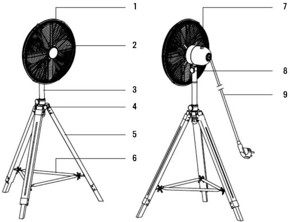
- Front grill
- Fan blades
- Standing pipe
- Tripod connection part
-
Tripod
-
Fixing base
- Motor housing and switch knob
- Motor and fan fixing knob
- Power cord and plug
ALSO INCLUDED
- Grill fixing screws (x4)
- Motor and fan fixing bolt (x1)
- Tilt adjustment screw (x1)
- Locating screw (x1)
- Grill locking screw (x1)
- Grill locking nut (x1)
-
Tripod connector securing screw (x3)
-
Metal connection parts (x3)
- Springs (x3)
- Tripod main nuts (x3)
- Butterfly screws for fixing base (x3)
- Base links (x3)
- Butterfly nuts for fixing base (x3)
The identification number of each connection piece is included in brackets in the assembly instructions below.
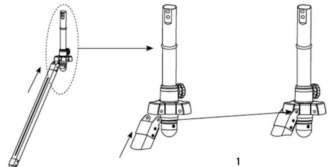
TRIPOD ASSEMBLY
natural_image
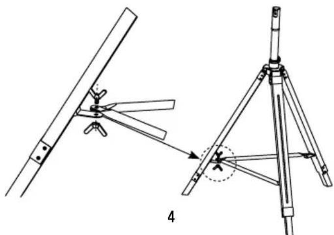
Technical line drawing of mechanical assembly with two views showing tool positioning and assembly (no text or symbols)Flx every wooden leg to its metal connection part (8) and then to the connection on the standing pipe.
natural_image
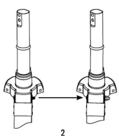
Technical line drawing of two mechanical components with a directional arrow indicating transformation (no text or symbols)Flx the tripod connector securing screw (7), spring (9) and tripod main nut (10).
natural_image
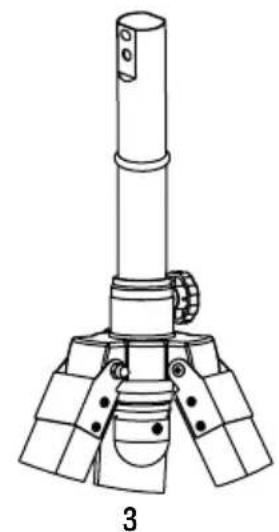
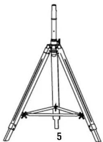
Technical line drawing of a mechanical device with three legs and a cylindrical shaft (no text or symbols)Repeat previous step with the three legs of the tripod.
natural_image
Technical line drawing of a mechanical assembly with two views (top and side), no text or symbols present.Fix the base links (12) to the tripod using the butterfly screws (11) and nuts (13).
natural_image
Technical line drawing of a tripod-mounted surveying instrument with no visible text or symbolsRepeat the previous step with every base link and tripod leg.
BLADE AND GRILL ASSEMBLY
natural_image
Diagram showing three stages of a fan blade system with blades radiating outward (no text or labels)1
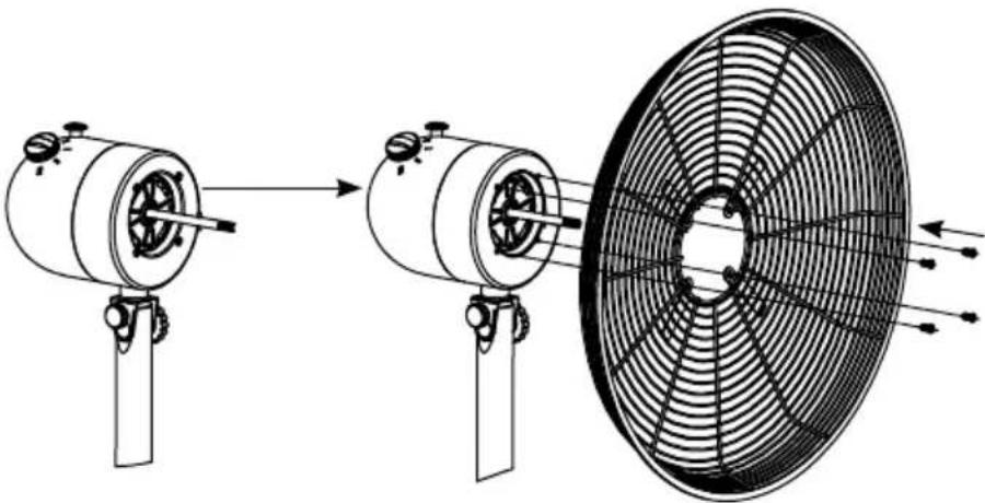
Flx the grill to the motor housing part using the 4 blade screws (1) provided.
natural_image
Line drawing of a two-blade air fan with a propeller, showing internal blades and mounting base (no text or symbols)2
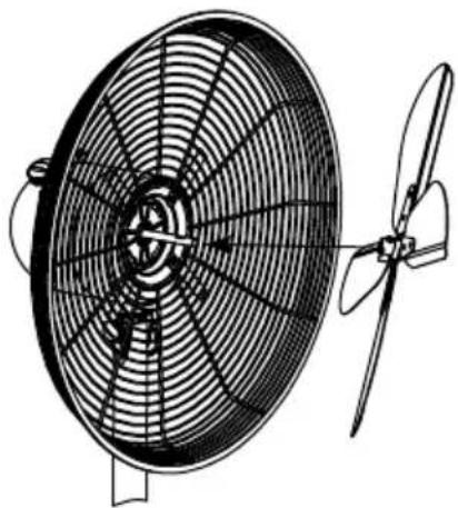
Then, flx the blades to the motor axis.
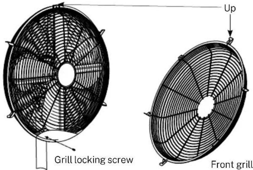
Fix the front grill to the back grill clamping the side flaps. To secure the fixing, screw the grill locking screw (5) at the bottom of both grills. Take into account the position of the front grill as in the picture above.
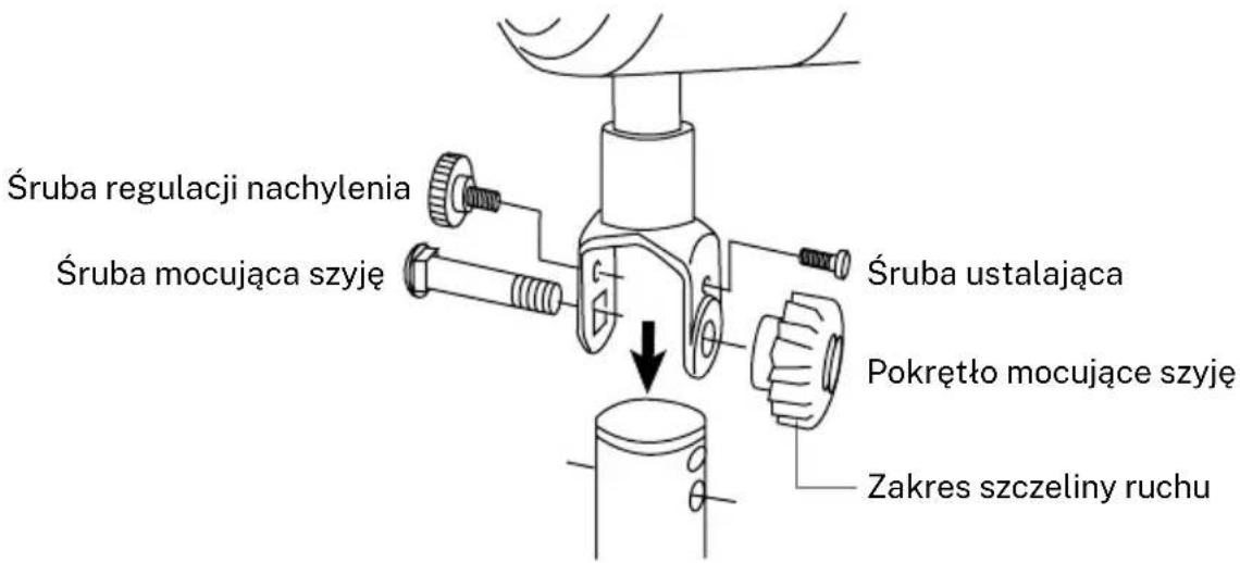
FAN HEAD ASSEMBLY
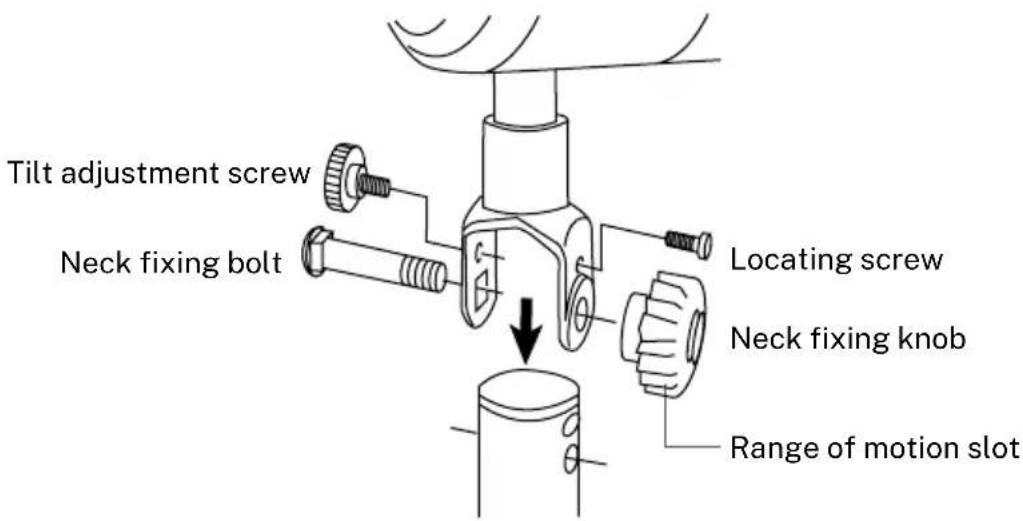
- The neck fixing bolt (2) and knob are used to fix the motor unit to the inner pole.
- The locating screw (4) is used to limit the tilting angle.
- The tilt adjustment screw (3) is used to adjust the tilt.
HOW TO USE THE FAN
The fan has three speed settings:
- 0 = OFF
- I = Low speed
• II = Medium speed -
III = High speed
-
The fan can operate in oscillating or stationary mode. Press the oscillation button to activate the oscillating mode.
- The height of the fan can also be adjusted: Loosen the screw to move the stand up or down as required. Tighten the screw at the desired position.
CLEANING
• Always switch the fan off and unplug it before cleaning.
- Clean the parts using a damp cloth and a mild detergent, and ensure that all detergent residues are removed.
- Never use abrasive cleaning agents or solvents.
- Do not immerse in any form of liquid.
WARNING: In order to reduce the risk of fire or electric shock, never use the appliance together with an electronic timer.
In compliance with Directives: 2012/19/EU and 2015/863/EU on the restriction of the use of dangerous substances in electric and electronic equipment as well as their waste disposal. The symbol with the crossed dustbin shown on the package indicates that the product at the end of its service life shall be collected as separate waste. Therefore, any products that have reached the end of their useful life must be given to waste disposal centres specialising in separate collection of waste electrical and electronic equipment, or given back to the retailer at the time of purchasing new similar equipment, on a one for one basis. The adequate separate collection for the subsequent start-up of the equipment sent to be recycled, treated and disposed of in an environmentally compatible way contributes to preventing possible negative effects on the environment and health and optimises the recycling and reuse of components making up the apparatus. Abusive disposal of the product by the user involves application of the administrative sanctions according to the laws.
natural_image
Line drawing of a tripod-mounted fan with labeled components (no text or symbols on the fan itself)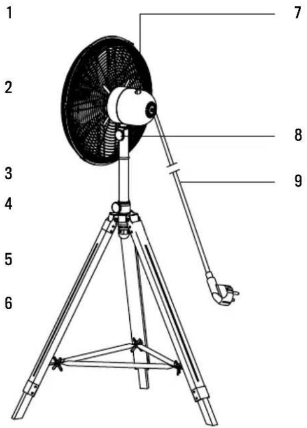
natural_image
Technical line drawing of mechanical assembly steps showing tool positioning and assembly (no text or symbols)natural_image
Technical line drawing of two mechanical components with a directional arrow indicating assembly (no text or symbols)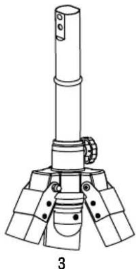
natural_image
Technical line drawing of a mechanical device with three legs and a central shaft (no text or symbols)natural_image
Technical line drawing of a mechanical assembly with two views (top and side), showing components like blades and legs, no text or symbols present.natural_image
Technical line drawing of a tripod-mounted surveying instrument with no visible text or symbolsnatural_image
Diagram showing three stages of a fan blade operation: before, after, and after the blade (no text or symbols present)1
natural_image
Line drawing of a double〕风扇与两扇 blades,无文字或 symbols2
natural_image
Technical line drawing of mechanical assembly with two views showing tool positioning and assembly steps (no text or symbols)natural_image
Diagram of two mechanical components with a directional arrow indicating transformation (no text or symbols)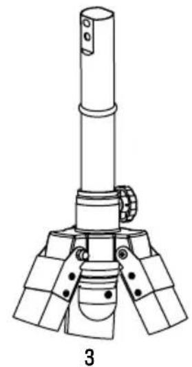
natural_image
Technical line drawing of a mechanical assembly with three legs and a central shaft (no text or symbols)natural_image
Technical line drawing of a mechanical assembly with two views (top and side), no text or symbols present.
natural_image
Technical line drawing of a tripod-mounted surveying instrument with no visible text or symbolsnatural_image
Diagram showing three stages of a fan blade operation: before, after, and after the blade (no text or symbols present)1
natural_image
Line drawing of a two-blade air fan with a propeller, showing internal blades and mounting base (no text or symbols)2
natural_image
Technical illustration of mechanical assembly steps showing tool positioning and assembly (no text or symbols)natural_image
Technical line drawing of two mechanical components with a directional arrow indicating transformation (no text or symbols)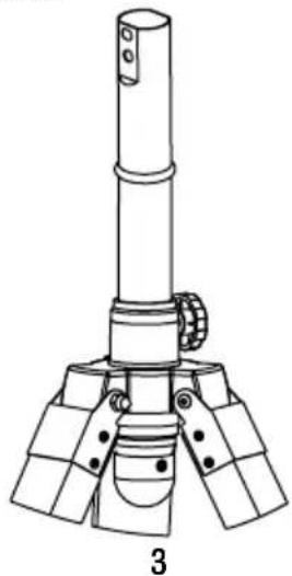
natural_image
Technical line drawing of a mechanical device with three legs and a central shaft (no text or symbols)natural_image
Technical line drawing of a mechanical assembly with two views (top and side), no text or symbols present.
natural_image
Technical line drawing of a tripod-mounted surveying instrument with no visible text or symbolsnatural_image
Diagram showing three stages of a fan blade operation: before, after, and after the blade (no text or symbols present)1
natural_image
Technical line drawing of a fan with blades and propeller (no text or symbols)2
natural_image
Line drawing of a three-legged tripod-mounted fan with visible blades and mounting brackets (no text or symbols)
natural_image
Technical line drawing of mechanical assembly with two views showing shafts and mounting features (no text or symbols)natural_image
Technical line drawing of two mechanical components with a directional arrow indicating transformation (no text or symbols)
natural_image
Technical line drawing of a mechanical device with three legs and a central shaft (no text or symbols)natural_image
Technical line drawing of a mechanical assembly with two views (top and side), no text or symbols present.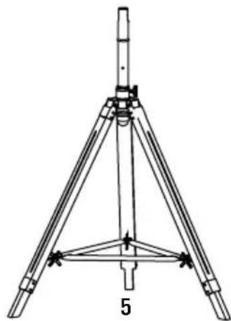
natural_image
Technical line drawing of a tripod-mounted surveying instrument with tripod base and support structure (no text or symbols)natural_image
Diagram showing three stages of a fan blade operation: before, after, and after the blade (no text or symbols present)1
natural_image
Line drawing of a two-blade air fan with a propeller, showing internal blades and mounting base (no text or symbols)2
natural_image
Technical line drawing of mechanical assembly with two views showing shafts and mounting features (no text or symbols)natural_image
Technical line drawing of two mechanical components with a directional arrow indicating transformation (no text or symbols)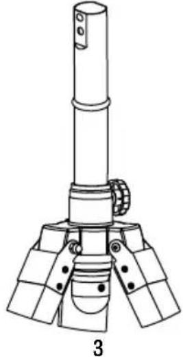
natural_image
Technical line drawing of a mechanical device with three legs and a cylindrical top, labeled '3' (no text or symbols on the diagram itself)natural_image
Technical line drawing of a mechanical assembly with two views (top and side), no text or symbols present.
natural_image
Technical line drawing of a tripod-mounted surveying instrument with no visible text or symbolsnatural_image
Diagram showing three stages of a fan blade operation: before, after, and after the blade (no text or symbols present)1
natural_image
Technical line drawing of a large fan with blades and a propeller, no text or symbols present2
natural_image
Line drawing of a three-legged tripod-mounted fan with visible blades and mounting brackets (no text or symbols)
natural_image
Technical line drawing of two mechanical components with a directional arrow indicating assembly (no text or symbols)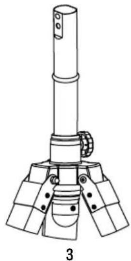
natural_image
Technical line drawing of a mechanical device with a cylindrical shaft and three base supports (no text or symbols)natural_image
Technical line drawing showing two mechanical assembly steps: left with a lever mechanism, right with a tripod-mounted component (no text or symbols)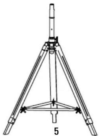
natural_image
Technical line drawing of a tripod-mounted surveying instrument with no visible text or symbolsnatural_image
Diagram showing three stages of a fan blade system with blades radiating outward (no text or labels)1
natural_image
Line drawing of a two-blade air fan with a propeller, showing internal blades and mounting base (no text or symbols)2
natural_image
Line drawing of a tripod-mounted fan with visible blades and base structure (no text or symbols)
natural_image
Technical line drawing of two mechanical components with a directional arrow indicating assembly (no text or symbols)natural_image
Technical line drawing of a mechanical device with three legs and a cylindrical top (no text or symbols)natural_image
Technical diagram showing two mechanical assembly steps: left with a lever mechanism, right with a tripod-mounted component (no text or symbols)natural_image
Technical line drawing of a tripod-mounted surveying instrument with no visible text or symbolsnatural_image
Diagram showing three stages of a fan blade assembly: before, after, and after the blade (no text or symbols present)1
natural_image
Line drawing of a two-blade air fan with a propeller, showing internal blades and mounting base (no text or symbols)2
ZESPÓŁ GŁOWICY WENTYLATORA

Brand : Create
Model : AIR TRIPOD RETRO
Category : Fan