
PXE 80 10.8-EC-0 - Grinder Flex - Free user manual and instructions
Find the device manual for free PXE 80 10.8-EC-0 Flex in PDF.

| Product Type | Cordless Polisher |
| Brand | Flex |
| Model | PXE 80 10.8-EC-0 |
| Battery Voltage | 10.8 V |
| Available Battery Capacities | 2.5 Ah / 4.0 Ah / 6.0 Ah |
| Battery Weight | 0.26 kg (2.5 Ah) / 0.42 kg (4.0 Ah) / 0.43 kg (6.0 Ah) |
| Variable Speed | 4 levels: 1-3 polishing, level 4 localized sanding |
| Drive Type | Rotary, random orbital (3 mm or 12 mm stroke) |
| Accessory Holder | Velcro ∅75 mm or ∅35 mm, or adhesive ∅35 mm |
| Sound Pressure Level (L_pA) | 68 dB(A) |
| Sound Power Level (L_WA) | 79 dB(A) |
| Total Vibration (polishing) | 6.53 m/s² |
| Operating Temperature | -10 °C to 40 °C |
| Storage Temperature | -40 °C to 70 °C |
| Protection | Removable hand guard, safety shut-off in case of overload |
| Intended Use | Commercial polishing of all surfaces with sponges, wool, felt |
| Maintenance | Regularly clean the ventilation slots, use dry compressed air |
| Spare Parts | Available at www.flex-tools.com |
| Warranty | Complies with EU directives, mandatory recycling |
Frequently Asked Questions - PXE 80 10.8-EC-0 Flex
User questions about PXE 80 10.8-EC-0 Flex
0 question about this device. Answer the ones you know or ask your own.
Ask a new question about this device
Download the instructions for your Grinder in PDF format for free! Find your manual PXE 80 10.8-EC-0 - Flex and take your electronic device back in hand. On this page are published all the documents necessary for the use of your device. PXE 80 10.8-EC-0 by Flex.
USER MANUAL PXE 80 10.8-EC-0 Flex
natural_image
Line drawing of a mechanical device with directional arrows indicating movement or force (no text or symbols)F
Eckhard Rühle Manager Research & Development (R & D)
Klaus Peter Weinper Head of Quality Department (QD)
Symbols used in this manual

WARNING!
Denotes impending danger. Non-observance of this warning may result in death or extremely severe injuries.

CAUTION!
Denotes a possibly dangerous situation. Non-observance of this warning may result in slight injury or damage to property.

NOTE
Denotes application tips and important information.
Symbols on the power tool
V
volts
/min Rotation rate

To reduce the risk of injury, read the operating instructions!

Disposal information for the old machine (see page 14)!
For your safety

WARNING!
Before using the power tool, please read and follow:
– these operating instructions,
- the "General safety instructions" on the handling of power tools in the enclosed booklet (leaflet-no.: 315.915),
– the currently valid site rules and the regulations for the prevention of accidents.
This power tool is state of the art and has been constructed in accordance with the acknowledged safety regulations.
Nevertheless, when in use, the power tool may be a danger to life and limb of the user or a third party, or the power tool or other property may be damaged.
The polisher may be used only
-asintended,
– in perfect working order.
Faults which impair safety must be repaired immediately.
Intended use
The polisher is designed
– for commercial use in industry and trade,
– for all types of polishing work with polishing sponges, lambskins and woolskins, felt plate, buffing disc,
– for use with polishing tools which are permitted to run at a speed of at least 5800 r.p.m
Safety instructions for polishing

WARNING!
Read all safety warnings, instructions, illustrations and specifications provided with this power tool. Failure to follow all instructions listed below may result in electric shock, fire and/or serious injury. Save all warnings and instructions for future reference.
This power tool is intended to function as a pollsher. Read all safety warnings, Instructions, Illustrations and specifications provided with this power tool. Failure to follow all instructions listed below may result in electric shock, fire and/or serious injury.
■ Operations such as grinding, sanding, wire brushing, or cutting-off are not recommended to be performed with this power tool. Operations for which the power tool was not designed may create a hazard and cause personal injury.
■ Do not use accessories which are not specifically designed and recommended by the tool manufacturer. Just because the accessory can be attached to your power tool, it does not assure safe operation.
■ The rated speed of the accessory must be at least equal to the maximum speed marked on the power tool. Accessories running faster than their rated speed can break and fly apart.
■ The outside diameter and the thickness of your accessory must be within the capacity rating of your power tool. Incorrectly sized accessories cannot be adequately guarded or controlled.
Threaded mounting of accessories must match the grinder spindle thread. For accessories mounted by flanges, the arbour hole of the accessory must fit the locating diameter of the flange. Accessories that do not match the mounting hardware of the power tool will run out of balance, vibrate excessively and may cause loss of control.
☐ Do not use a damaged accessory. Before each use Inspect the accessory such as abrasive wheels for chips and cracks, backing pad for cracks, tear or excess wear, wire brush for loose or cracked wires. If power tool or accessory is dropped, Inspect for damage or Install an undamaged accessory. After Inspecting and Installing an accessory, position yourself and bystanders away from the plane of the rotating accessory and run the power tool at maximum no-load speed for one minute. Damaged accessories will normally break apart during this test time.
■ Wear personal protective equipment. Depending on application, use face shield, safety goggles or safety glasses. As appropriate, wear dust mask, hearing protectors, gloves and shop apron capable of stopping small abrasive or workpiece fragments. The eye protection must be capable of stopping flying debris generated by various operations. The dust mask or respirator must be capable of filtrating particles generated by your operation. Prolonged exposure to high intensity noise may cause hearing loss.
- Keep bystanders a safe distance away from work area. Anyone entering the work area must wear personal protective equipment. Fragments of workpiece or of a broken accessory may fly away and cause injury beyond immediate area of operation.
■ Never lay the power tool down until the accessory has come to a complete stop. The spinning accessory may grab the surface and pull the power tool out of your control.
■ Do not run the power tool while carrying it at your side. Accidental contact with the spinning accessory could snag your clothing, pulling the accessory into your body.
- Regularly clean the power tool's air vents. The motor's fan will draw the dust inside the housing and excessive accumulation of powdered metal may cause electrical hazards.
■ Do not operate the power tool near flammable materials. Sparks could ignite these materials.
■ Do not use accessories that require liquid coolants. Using water or other liquid coolants may result in electrocution or shock.
Kickback and Related Warnings:
Kickback is a sudden reaction to a pinched or snagged rotating wheel, backing pad, brush
or any other accessory. Pinching or snagging causes rapid stalling of the rotating accessory which in turn causes the uncontrolled power tool to be forced in the direction opposite of the accessory's rotation at the point of the binding. For example, if an abrasive wheel is snagged or pinched by the workpiece, the edge of the wheel that is entering into the pinch point can dig into the surface of the material causing the wheel to climb out or kick out. The wheel may either jump toward or away from the operator, depending on direction of the wheel's movement at the point of pinching. Abrasive wheels may also break under these conditions. Kickback is the result of power tool misuse and/or incorrect operating procedures or conditions and can be avoided by taking proper precautions as given below.
■ Maintain a firm grip on the power tool and position your body and arm to allow you to resist kickback forces. Always use auxiliary handle, if provided, for maximum control over kickback or torque reaction during start-up. The operator can control torque reactions or kickback forces, if proper precautions are taken.
□■Never place your hand near the rotating accessory. Accessory may kickback over your hand.
- Do not position your body in the area where power tool will move if kickback occurs. Kickback will propel the tool in direction opposite to the wheel's movement at the point of snagging.
■ Use special care when working corners, sharp edges etc. Avoid bounding and snagging the accessory. Corners, sharp edges or bouncing have a tendency to snag the rotating accessory and cause loss of control or kickback.
Safety Warnings Specific for Polishing Operations:
☐ Do not allow any loose portion of the polishing bonnet or its attachment strings to spin freely. Tuck away or trim any loose attachment strings. Loose and spinning attachment strings can entangle your fingers or snag on the workpiece.
Noise and vibration
The noise and vibration values have been determined in accordance with EN 62841. The A evaluated noise level of the power tool is typically:
- Sound pressure level L_pA : 68 dB(A);
- Sound power level L_WA : 79 dB(A);
- Uncertainty: K = 3.0 dB.
Total vibration value (when polishing painted surfaces):
- Emission value a : 6.53 m/s ^2
– Uncertainty: K = 1.5 m/s ^2

CAUTION!
The indicated measurements refer to new power tools. Daily use causes the noise and vibration values to change.

NOTE
The vibration emission level given in this information sheet has been measured in accordance with a standardised test given in EN 62841 and may be used to compare one tool with another.
It may be used for a preliminary assessment of exposure. The declared vibration emission level represents the main applications of the tool. However if the tool is used for different applications, with different accessories or poorly maintained, the vibration emission may differ. This may significantly increase the exposure level over the total working period. For a precise estimation of the vibration load the times should also be considered during which the power tool is switched off or even running, but not actually in use. This may significantly decrease the exposure level over the total working period. Identify additional safety measures to protect the operator from the effects of vibration such as: maintain the tool and the accessories, keep the hands warm, organisation of work patterns.

CAUTION!
Wear ear protection at a sound pressure above 85 dB(A).
Technical specifications
| PXE 80 10.8-EC | Polisher | ||
| Battery AP | 10.8/2.5 | AP10.8/4.0 | AP10.8/6.0 |
| Weight of battery/kg | 0.26 0. | 42 0.43 | |
| Average battery life (depending on speed, tool diameter, load ...)/min | 20 35 | 50 | |
| Working Temperature | -10~40°C | ||
| Storage Temperature | -40~70°C | ||
| Charging Temperature | 5~40°C | ||
| Charger CA 10.8/18.0 | |||
Other specifications see figure B
Overview (see figure A)
The numbering of the product features refers to the illustration of the machine on the graphics page.
1 Movable shield
2 Speed control button
- +/- function with 4 levels
– Level 1-3 "Polishing", Level 4 "spot sanding"
3 Switch
Switches the power tool on and off and also accelerates it up to the preselected speed.
4 Gear head with handle cover
With air outlet and direction-of-rotation arrow.
5 Rating plate
6 Slot for battery
7 State of charge indicator
8 Release button for battery
9 Li-ion battery (2.5 Ah or 4.0 Ah or 6.0 Ah)
10 Backing plate
- 10/1 = polishing and sanding (velcro) backing plat ∅75mm, can be combined with drive types 11/2 and 11/3
- 10/2 = polishing and sanding (velcro) backing plat ∅35mm, can be combined with all types of drive.
- 10/3 = sanding backing plat ∅35mm for (glue) spot sanding pads, can be combined with all types of drive.
11 Drive types
- 11/1 = rotary drive type, for polishing and sanding, can not be combined with the backing plate ∅75mm (10/1).
- 11/2 = random orbital with 3mm stroke for polishing and sanding, can be combined with all backing plats - 11/3 = random orbital with 12mm stroke for polishing, can be combined with all backing plats
*Accessories shown or described are not part of the standard delivery scope of the product.
Operating instructions

WARNING!
Remove the battery before carrying out any work on the power tool.
Before switching on the power tool
Unpack the polisher and check that there are no missing or damaged parts.

NOTE
The batteries are not fully charged on delivery. Prior to initial operation, charge the batteries fully. Refer to the charger operating manual.
Inserting/replacing the battery
■Press the charged battery 8 into the power tool until it clicks into place. (see figure C)
■To remove, press the release button 7 and pull out the battery. (see figure D)

CAUTION!
When the device is not in use, protect the battery contacts. Loose metal parts may short-circuit the contacts; explosion and fire hazard!
Battery state of charge
■Press the button to check the state of charge at the state of charge indicator LEDs 7.
The indicator goes out after 5 seconds. If one of the LEDs flashes, the battery must be recharged. If none of the LEDs light up after the button is pressed, the battery is faulty and must be replaced.
Attaching tool holder (see figure E)
■Threaded mounting the backing plate 10 to the driver types 11.
■Push down the movable shield 1.
■Insert the driver types 11 onto the hole of the spindle.
■Release the shield.
Changing tool holder
■Push down the movable shield 1.
■Remove the driver types 11 from the hole of the spindle.
■Insert new driver types
■Release the ring.
Attaching the tools

CAUTION!
Attach tools centrally on tool holder. Imbalances may damage the power tool. The work result may be impaired.

NOTE
Use original FLEX accessories on this model. Not using original FLEX accessories may lead to a poor polishing result, increased vibrations and also greater wear or even damage to the power tool.
Information concerning foam wear

NOTE
In general, foam wear is much higher in connection with free-wheeling eccentric polishing that with rotational polishing or force-driven eccentric polishing.
Due to the drive, this wear does not take place on the outside of the foam but at the foam core instead. The harder/longer the cell structure is subjected to strain and damaged as a result, the faster the build-up of heat. Subsequent damage is inevitable. Wear of this kind cannot be seen on the foam externally. The only reliable action is replacement and disposal in good time to prevent thermal damage to the power tool.
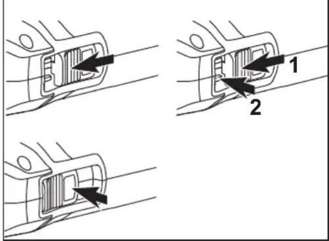
Switching on and off (see figure F)
Brief operation without engaged switch rocker
■Push the switch rocker 3 forwards and engage by pressing the front end.
■To switch off the power tool, release the switch rocker by pressing the rear end.
Preselecting the speed
■To set the operating speed, press the speed control button 2. Selected speed is maintained even when switching off. With the exception of level 4, this always goes back to level 3 after switching off (safety).
■Gently press the switch to accelerate the power tool up to the preselected speed.

CAUTION!
Risk of injury due to destruction of the tool. Use the appropriate tool for the job.

NOTE
In the event of overload or overheating in non-stop operation, the power tool will switch off.
To continue working, switch the power tool off and back on again.
i NOTE
When the power tool is switched off, the tool continues running briefly.
If using a polishing paste, use the respective tool for each paste.
Sponges can be washed in the washing machine.
For further information on the manufacturer's products go to www.flex-tools.com.
Maintenance and care
WARNING!
Remove the battery before carrying out any work on the power tool.
Cleaning
■Clean the power tool and grille in front of the vent slots regularly. Frequency of cleaning is dependent on the material and duration of use.
■Regularly blow out the housing interior and motor with dry compressed air.
Spare parts and accessories
For other accessories, in particular tools and polishing aids, see the manufacturer's catalogues.
Exploded drawings and spare-part lists can be found on our homepage:
www.flex-tools.com
Disposal information
WARNING!
Render redundant power tools unusable:
- mains operated power tool by removing the power cord,
- battery operated power tool by removing the battery.

EU countries only Do not throw electric power tools into the household waste!
In accordance with the European Directive 2012/19/EU on Waste Electrical and Electronic Equipment and transposition into national law used electric power tools must be collected separately and recycled in an environmentally friendly manner.

Raw material recovery instead of waste disposal.
Device, accessories and packaging should be recycled in an environmentally friendly manner. Plastic parts are identified for recycling according to material type.
WARNING!
Do not throw batteries into the household waste, fire or water. Do not open used batteries.
EU countries only: In accordance with Directive 2006/66/EC defective or used batteries must be recycled.
i NOTE
Please ask your dealer about disposal options!
C ∈ -Declaration of Conformity
We declare under our sole responsibility that the product described under “Technical specifications” conforms to the following standards or normative documents:
EN 62841 in accordance with the regulations of the directives 2014/30/EU, 2006/42/EC, 2011/65/EU.
Responsible for technical documents: FLEX-Elektrowerkzeuge GmbH, R & D Bahnhofstrasse 15, D-71711 Steinheim/Murr

Eckhard Rühle Manager Research & Development (R & D)
Klaus Peter Weinper Head of Quality Department (QD)
Exemption from liability
The manufacturer and his representative are not liable for any damage and lost profit due to interruption in business caused by the product or by an unusable product. The manufacturer and his representative are not liable for any damage which was caused by improper use of the power tool or by use of the power tool with products from other manufacturers.
Eckhard Rühle Manager Research & Development (R & D)
Klaus Peter Weinper Head of Quality Department (QD)
Eckhard Rühle Manager Research & Development (R & D)
Klaus Peter Weinper Head of Quality Department (QD)
Fixar as ferramentas
CUIDADO!
Eckhard Rühle
Manager Research & Development (R & D)
Klaus Peter Weinper
Head of Quality Department (QD)
9 Li-lon accu(2,5 Ah of 4,0 Ah of 6,0 Ah)
10 Steunplaat
Eckhard Rühle Manager Research & Development (R & D)
Klaus Peter Weinper Head of Quality Department (QD)
Klaus Peter Weinper Head of Quality Department (QD)
Eckhard Rühle Manager Research & Development (R & D)
Klaus Peter Weinper Head of Quality Department (QD)
Manager Research & Development (R & D)
Klaus Peter Weinper Head of Quality Department (QD)
Eckhard Rühle Manager Research & Development (R & D)
Klaus Peter Weinper Head of Quality Department (QD)
Eckhard Rühle
Manager Research &
Development (R & D)
Klaus Peter Weinper
Head of Quality
Department (QD)
Eckhard Rühle
Manager Research & Development (R & D)
Klaus Peter Weinper
Head of Quality
Department (QD)
Eckhard Rühle Manager Research & Development (R & D)
Klaus Peter Weinper Head of Quality Department (QD)
Eckhard Rühle
Manager Research &
Development (R & D)
Klaus Peter Weinper
Head of Quality
Department (QD)
Eckhard Rühle
Manager Research &
Development (R & D)
Klaus Peter Weinper
Head of Quality
Department (QD)
Eckhard Rühle Manager Research & Development (R & D)
Klaus Peter Weinper Head of Quality Department (QD)
Eckhard Rühle Manager Research & Development (R & D)
Klaus Peter Weinper Head of Quality Department (QD)
Eckhard Rühle Manager Research & Development (R & D)
Klaus Peter Weinper Head of Quality Department (QD)
Klaus Peter Weinper Head of Quality Department (QD)
Eckhard Rühle Manager Research & Development (R & D)
Klaus Peter Weinper Head of Quality Department (QD)
Klaus Peter Weinper Head of Quality Department (QD)
Eckhard Rühle
Manager Research &
Development (R & D)
Klaus Peter Weinper
Head of Quality
Department (QD)
Eckhard Rühle
Manager Research &
Development (R & D)
Klaus Peter Weinper
Head of Quality
Department (QD)
HbmG eguezkrewortkelE-XELF ;9102.51.40
rruM/miehnietS 11717-D ,51 essarstfohnhaB
إعفاء من المسوّلية


- Symbols used in this manual
- WARNING!
- CAUTION!
- NOTE
- Symbols on the power tool
- For your safety
- Intended use
- Safety instructions for polishing
- Kickback and Related Warnings:
- Safety Warnings Specific for Polishing Operations:
- Noise and vibration
- Technical specifications
- Overview (see figure A)
- Operating instructions
- Before switching on the power tool
- Inserting/replacing the battery
- Battery state of charge
- Attaching tool holder (see figure E)
- Changing tool holder
- Attaching the tools
- Information concerning foam wear
- Switching on and off (see figure F)
- Preselecting the speed
- i NOTE
- Maintenance and care
- Cleaning
- Spare parts and accessories
- Disposal information
- C ∈ -Declaration of Conformity
- Exemption from liability
- Fixar as ferramentas
- CUIDADO!
- إعفاء من المسوّلية
Brand : Flex
Model : PXE 80 10.8-EC-0
Category : Grinder