45221 - Electrical measuring tool Wiha - Free user manual and instructions
Find the device manual for free 45221 Wiha in PDF.

User questions about 45221 Wiha
0 question about this device. Answer the ones you know or ask your own.
Ask a new question about this device
Download the instructions for your Electrical measuring tool in PDF format for free! Find your manual 45221 - Wiha and take your electronic device back in hand. On this page are published all the documents necessary for the use of your device. 45221 by Wiha.
USER MANUAL 45221 Wiha
natural_image
Icon of an open book inside a dark circle (no text or symbols)DE....3 NO....66
EN....12 SV....75
FR....21 FI....84
NL....30 PL....93
ES....39 CS....102
IT....48 RU....111
DA....57 HU....120
BEDIENUNGSANLEITUNG
Inhaltsverzeichnis
Website: www.wiha.com
Introduction / Scope of supply 14
Transport and storage 15
Safety 15
Appropriate usage 16
Control elements and connections 17
Determination of the rotary field direction 17
Maintenance 18
Cleaning 18
Technical data....19
Service and warranty....20
References marked on instrument or in instruction manual

Warning of a potential danger, follow with instruction manual.

Caution! Dangerous voltage. Danger of electrical shock.

Reference! Please use utmost attention.

Continuous double or reinforced insulation category II IEC 536.

Complies with EU specifications.

Complies with UK specifications.
Instrument fulfill the standard (2012/19/EU) WEEE. This marking indicates that this product should not be disposed with other household wastes throughout the EU. To prevent possible harm to the environment or human health from uncontrolled waste disposal, recycle it responsibly to promote the sustainable reuse of material resources. To return your used device, please use the return and collection systems or contact the retailer where the product was purchased. They can take this product for environmental safe recycling.
INSTRUCTION MANUAL
Introduction / Scope of supply

The instruction manual contains information and references, necessary for safe operation and maintenance of the instrument. Prior to using the instrument (commissioning / assembly) the user is kindly requested to thoroughly read the instruction manual and comply with it in all sections. Failure to read the instruction manual or to follow with the warnings and references contained herein can result in serious bodily injury or instrument damage. The respective accident prevention regulations established by the professional associations are to be strictly enforced at all times.
The handy phase rotation indicator 45221 represents an appropriate test instrument for the determination of rotary field directions.
• Display of all three phases via LED
• Definition of the direction of the rotary field via LED
• Voltage range 100...700 V
• Frequency range 50...60 Hz
- No batteries needed
Scope of supply
• 1x Phase rotation indicator 45221
- 3x Test probes
• 1x Instruction manual
Transport and storage
Please keep the original packaging for later transport, e.g. for calibration. Any transport damage due to faulty packaging will be excluded from warranty claims.
Instruments must be stored in dry and closed areas.
In the case of an instrument being transported in extreme temperatures, a recovery time of minimum 2 hours is required prior to instrument operation.
Safety

The phase rotation indicator has been constructed and verified in compliance with the latest safety standards for Test Instruments IEC/EN 61010-1, IEC/EN 61010-031 and IEC/EN 61557-7 and have left the factory in safe and perfect conditions.

In order to avoid electrical shock, the valid safety and VDE regulations regarding excessive contact voltages must receive utmost attention, when working with voltages exceeding 120 V (60 V) DC or 50 V (25 V) rms AC. The values in brackets are valid for limited ranges (as for example medicine and agriculture).
Prior to usage ensure perfect instrument function. The instrument may only be used within the operating ranges as specified in the technical data section.
If the operator's safety is no longer ensured, the instrument is to be put out of service and protected against use.
INSTRUCTION MANUAL
The safety can no longer be insured if the instrument
• shows obvious damage.
- does not carry out the desired measurements.
- has been stored for too long under unfavourable conditions.
• has been subjected to mechanical stress during transport.
The instrument may only be used under those conditions and for those purposes for which it was conceived. For this reason, in particular the safety references, the technical data including environmental conditions and the usage in dry environments must be followed. When modifying or changing the instrument, the operational safety is no longer ensured.
The respective accident prevention regulations established by the professional associations for electrical systems and equipment must be strictly met at all times.
Avoid any heating up of the instrument by direct sunlight to ensure perfect functioning and long instrument life.
Appropriate usage
The instrument may only be used under those conditions and for those purposes for which it was conceived. For this reason, in particular the safety references, the technical data including the environmental conditions and the usage in dry environments must be followed.
Operational safety is no longer guaranteed in the event of modifications and conversions.
Never operate the device at a higher voltage than specified in the technical data! Otherwise, the device may be destroyed or permanently damaged. In addition, there is a risk of electric shock for the operator.
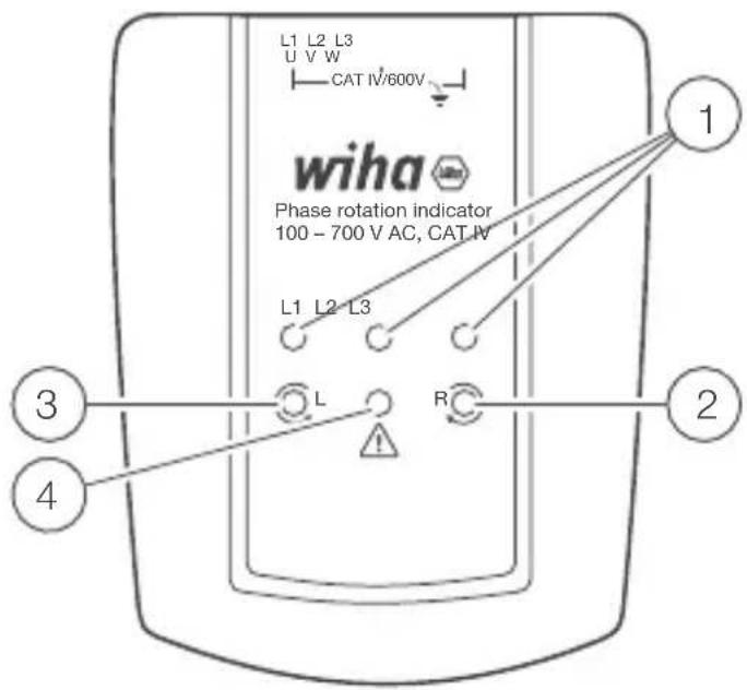
Control elements and connections
① LEDs for indication of the individual phases L1, L2, and L3
② LED to display clockwise rotary direction (right-hand rotation)
③ LED to display counter-clockwise rotary direction (left-hand rotation)
④ LED to indicate a faulty circuit
Determination of the rotary field direction
Within a three-phase system the sequence of the three phases determine the rotary direction of a motor connected. The correct phase sequence L1, L2, L3 results in a clockwise rotation.
To determine the phase sequence, the three terminals L1, L2, L3 are connected to the three-phase mains in any order.
- If the LED "R" lights up, a clockwise rotating field is present. The phase sequence is therefore correct.
- If the LED "L" lights up, the phase sequence is not correct. In this case, two connections are reversed.
INSTRUCTION MANUAL
If a phase is missing, the warning LED lights up to indicate that no clear phase sequence (direction of rotation) can be recognized.
If the neutral conductor N or the protective conductor PE is connected to a measuring input instead of L1, L2 or L3, the warning LEDs will also light up. Thus, a faulty connection is also indicated in this case.
Maintenance
When using the instrument in compliance with the instruction manual, no special maintenance is required.
Cleaning
If the instrument is dirty after daily usage, it is advised to clean it by using a humid cloth and a mild household detergent. Prior to cleaning, ensure that instrument is disconnected from external voltage supply and any other instruments connected. Never use acid detergents or resolvent for cleaning. After cleaning, do not use the phase rotation indicator for a period of approx. 2 h.
Technical data
Phase indication 3x LED "L1", "L2", "L3"
Phase rotation indication 2x LED "R", "L"
Warning indication 1x LED
Voltage phase to phase 100...700 V
Max. input voltage per 400 V
phase (Lx) against neutral (N)
Frequency 50...60 Hz
Input current ≤ 3.5 mA
Measurement category CAT IV, max. 600 V against earth
Pollution degree 2
Temperature range 0...40 °C
Height above sea level ≤ 2,000 m
Protection degree IP 40
Safety IEC/EN 61010-1, IEC/EN 61557-7,
IEC/EN 611010-031
Dimension approx. 93 x 75 x 31 mm
Weight approx. 115 g (without cables)
INSTRUCTION MANUAL
Service and warranty
Should the device no longer work, should you have any questions or require information, contact an authorised customer service point for Wiha power tools:
Customer care
Wiha Werkzeuge GmbH
Obertalstraße 3 – 7
78136 Schonach
GERMANY
Tel.: +49 7722 959-0
Fax: +49 7722 959-160
Email: info.de@wiha.com
Website: www.wiha.com
The warranty is voided in the event of injury or damage to property caused due to non-compliance with these instructions. The manufacturer accepts no liability for consequential damage!
MODE D'EMPLOI
Table des matières
Website: www.wiha.com
Tools that work for you
Wiha Werkzeuge GmbH
Obertalstraße 3 – 7
78136 Schonach
GERMANY
Tel.: +49 7722 959-0
Fax: +49 7722 959-160
Website: www.wiha.com