
CJ160VA - Saw HiKOKI - Free user manual and instructions
Find the device manual for free CJ160VA HiKOKI in PDF.

| Product Type | Jigsaw |
| Brand | HiKOKI |
| Model | CJ160VA |
| Power Supply | 800 W, 110-240 V~, 50/60 Hz |
| No-load Speed | 800 – 2800 min⁻¹ (standard mode); AUTO mode: 1400/2800 min⁻¹ |
| Stroke | 26 mm |
| Max. Cutting Depth (Wood) | 160 mm |
| Max. Cutting Depth (Mild Steel) | 10 mm |
| Min. Cutting Radius | 25 mm |
| Weight | 2.6 kg (EPTA 01/2014) |
| Operating Modes | Standard mode (adjustable speed) and AUTO mode (automatic adaptation) |
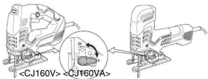
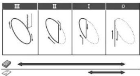
| Orbit Function | Yes, adjustable (positions 0-3) |
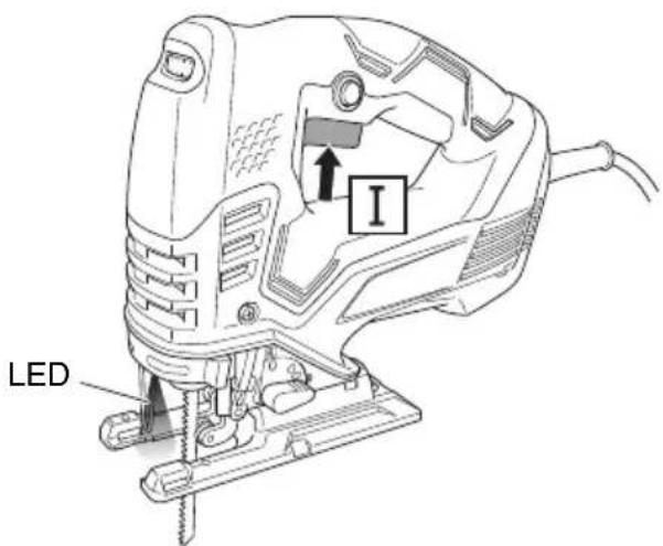
| Lighting | Built-in LED |
| Blade Change | Tool-free (release lever) |
| Safety | Residual Current Device (RCD) recommended; on/off switch; class II insulation |
| Sound Level (Power) | 96 dB(A); uncertainty K=5 dB(A) |
| Sound Level (Pressure) | 85 dB(A); uncertainty K=5 dB(A) |
| Vibrations (Wood Cutting) | 9.5 m/s²; uncertainty K=1.5 m/s² |
| Vibrations (Metal Cutting) | 7.0 m/s²; uncertainty K=1.5 m/s² |
| Included Accessories | Blades (No.41, No.123X), secondary base, hex key, chip guard, dust collector, chip cover |
| Warranty | Compliant with national regulations; manufacturing defects covered |
Frequently Asked Questions - CJ160VA HiKOKI
User questions about CJ160VA HiKOKI
0 question about this device. Answer the ones you know or ask your own.
Ask a new question about this device
Download the instructions for your Saw in PDF format for free! Find your manual CJ160VA - HiKOKI and take your electronic device back in hand. On this page are published all the documents necessary for the use of your device. CJ160VA by HiKOKI.
USER MANUAL CJ160VA HiKOKI
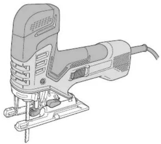
natural_image
Line drawing of a Jigsaw tool with visible screw base and mounting base (no text or symbols)CJ160V CJ160VA
natural_image
Line drawing of a J-shaped tool with screw base and mounting base (no text or symbols)
en Handling instructions
de Bedienungsanleitung
fr Mode d'emploi
it Istruzioni per l'uso
nl Gebruiksaanwijzing
es Instrucciones de manejo
pt Instruções de uso
SV Bruksanvisning
da Brugsanvisning
no Bruksanvisning
fi Käyttöohjeet
el Οδηγίες χειρισμού
pl Instrukcja obsługi
hu Kezelési utasítás
cs Návod k obsluze
tr Kullanım talimatları
ro Instructiuni de utilizare
sl Navodila za rokovanje
sk Pokyny na manipuláciu
bg Инструкция за експлоатация
sr Uputstvo za rukovanje
hr Upute za rukovanje
(Original instructions)
GENERAL POWER TOOL SAFETY WARNINGS

WARNING
Read all safety warnings, instructions, illustrations and specifications provided with this power tool.
Failure to follow all instructions listed below may result in electric shock, fire and/or serious injury.
Save all warnings and instructions for future reference.
The term “power tool” in the warnings refers to your mains-operated (corded) power tool or battery-operated (cordless) power tool.
1) Work area safety
a) Keep work area clean and well lit.
Cluttered or dark areas invite accidents.
b) Do not operate power tools in explosive atmospheres, such as in the presence of fl ammable liquids, gases or dust.
Power tools create sparks which may ignite the dust or fumes.
c) Keep children and bystanders away while operating a power tool.
Distractions can cause you to lose control.
2) Electrical safety
a) Power tool plugs must match the outlet. Never modify the plug in any way. Do not use any adapter plugs with earthed (grounded) power tools.
Unmodified plugs and matching outlets will reduce risk of electric shock.
b) Avoid body contact with earthed or grounded surfaces, such as pipes, radiators, ranges and refrigerators.
There is an increased risk of electric shock if your body is earthed or grounded.
c) Do not expose power tools to rain or wet conditions.
Water entering a power tool will increase the risk of electric shock.
d) Do not abuse the cord. Never use the cord for carrying, pulling or unplugging the power tool.
Keep cord away from heat, oil, sharp edges or moving parts.
Damaged or entangled cords increase the risk of electric shock.
e) When operating a power tool outdoors, use an extension cord suitable for outdoor use.
Use of a cord suitable for outdoor use reduces the risk of electric shock.
f) If operating a power tool in a damp location is unavoidable, use a residual current device (RCD) protected supply.
Use of an RCD reduces the risk of electric shock.
3) Personal safety
a) Stay alert, watch what you are doing and use common sense when operating a power tool.
Do not use a power tool while you are tired or under the influence of drugs, alcohol or medication.
A moment of inattention while operating power tools may result in serious personal injury.
b) Use personal protective equipment. Always wear eye protection.
Protective equipment such as a dust mask, non-skid safety shoes, hard hat or hearing protection used for appropriate conditions will reduce personal injuries.
c) Prevent unintentional starting. Ensure the switch is in the off -position before connecting to power source and/or battery pack, picking up or carrying the tool.
Carrying power tools with your fi nger on the switch or energising power tools that have the switch on invites accidents.
d) Remove any adjusting key or wrench before turning the power tool on.
A wrench or a key left attached to a rotating part of the power tool may result in personal injury.
e) Do not overreach. Keep proper footing and balance at all times.
This enables better control of the power tool in unexpected situations.
f) Dress properly. Do not wear loose clothing or jewellery. Keep your hair and clothing away from moving parts.
Loose clothes, jewellery or long hair can be caught in moving parts.
g) If devices are provided for the connection of dust extraction and collection facilities, ensure these are connected and properly used.
Use of dust collection can reduce dust-related hazards.
h) Do not let familiarity gained from frequent use of tools allow you to become complacent and ignore tool safety principles.
A careless action can cause severe injury within a fraction of a second.
4) Power tool use and care
a) Do not force the power tool. Use the correct power tool for your application.
The correct power tool will do the job better and safer at the rate for which it was designed.
b) Do not use the power tool if the switch does not turn it on and off.
Any power tool that cannot be controlled with the switch is dangerous and must be repaired.
c) Disconnect the plug from the power source and/or remove the battery pack, if detachable, from the power tool before making any adjustments, changing accessories, or storing power tools.
Such preventive safety measures reduce the risk of starting the power tool accidentally.
d) Store idle power tools out of the reach of children and do not allow persons unfamiliar with the power tool or these instructions to operate the power tool.
Power tools are dangerous in the hands of untrained users.
e) Maintain power tools and accessories. Check for misalignment or binding of moving parts, breakage of parts and any other condition that may affect the power tool's operation. If damaged, have the power tool repaired before use.
Many accidents are caused by poorly maintained power tools.
f) Keep cutting tools sharp and clean.
Properly maintained cutting tools with sharp cutting edges are less likely to bind and are easier to control.
g) Use the power tool, accessories and tool bits etc. in accordance with these instructions, taking into account the working conditions and the work to be performed.
Use of the power tool for operations different from those intended could result in a hazardous situation.
h) Keep handles and grasping surfaces dry, clean and free from oil and grease.
Slippery handles and grasping surfaces do not allow for safe handling and control of the tool in unexpected situations.
5) Service
a) Have your power tool serviced by a qualified repair person using only identical replacement parts.
This will ensure that the safety of the power tool is maintained.
PRECAUTION
Keep children and infi rm persons away.
When not in use, tools should be stored out of reach of children and infi rm persons.
JIG SAW SAFETY WARNINGS
- Hold the power tool by insulated gripping surfaces, when performing an operation where the cutting accessory may contact hidden wiring or its own cord.
Cutting accessory contacting a "live" wire may make exposed metal parts of the power tool "live" and could give the operator an electric shock.
- Use clamps or another practical way to secure and support the workpiece to a stable platform.
Holding the workpiece by hand or against your body leaves it unstable and may lead to loss of control.
ADDITIONAL SAFETY WARNINGS
- This jig saw employs a high-power motor. If the machine is used continuously at low speed, an extra load is applied to the motor which can result in motor seizure. Always operate the power tool so that the blade is not caught by the material during operation. Always adjust the blade speed to enable smooth cutting.
- Ensure that the power source to be utilized conforms to the power requirements specified on the product nameplate.
- Ensure that the power switch is in the OFF position.
If the plug is connected to a receptacle while the power switch is in the ON position, the power tool will start operating immediately, which could cause a serious accident.
- When the work area is removed from the power source, use an extension cord of sufficient thickness and rated capacity. The extension cord should be kept as short as practicable.
- Dust produced in operation
The dust produced in normal operation may affect the operator's health. Either of following way is recommended.
a) Wear a dust mask
b) Use external dust collection equipment
When using the external dust collection equipment, connect the adapter with the hose from external dust collection equipment.
- During use, do not touch the metal portion of the tool.
-
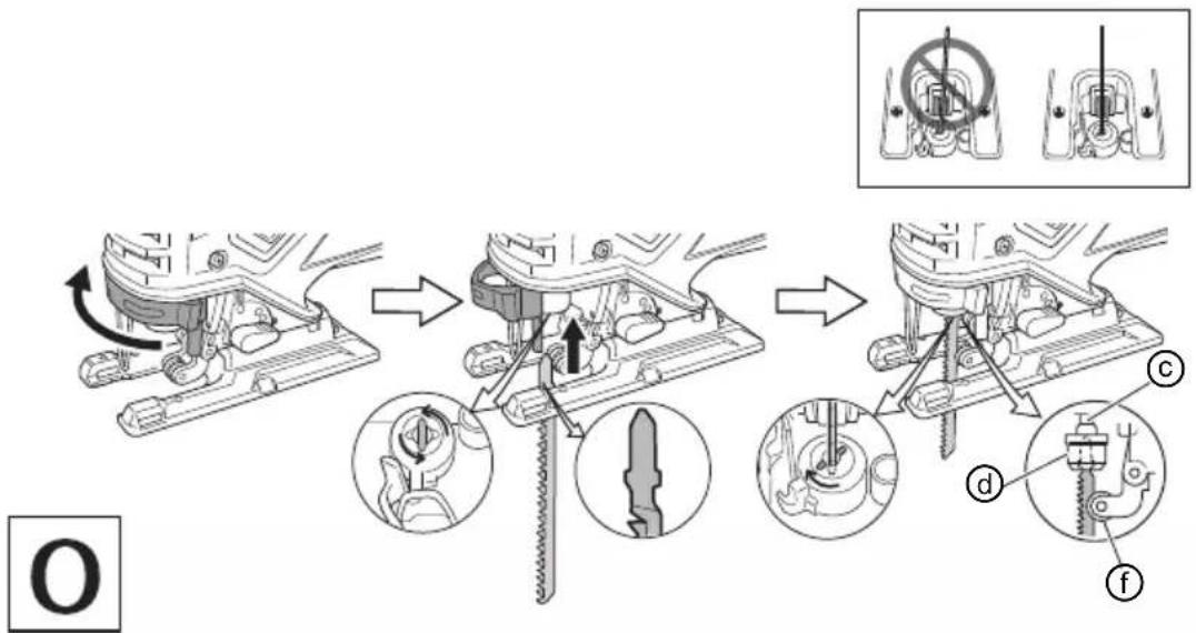
Changing blades
○ Be sure to switch power OFF and disconnect the plug from the receptacle when changing blades.
○ Do not open the lever when plunger is moving.
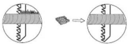
○ Confirm the protrusions of blade inserted to the blade holder surely. (Fig. 2)
○ Confirm the blade located between the groove of roller. (Fig. 2) -
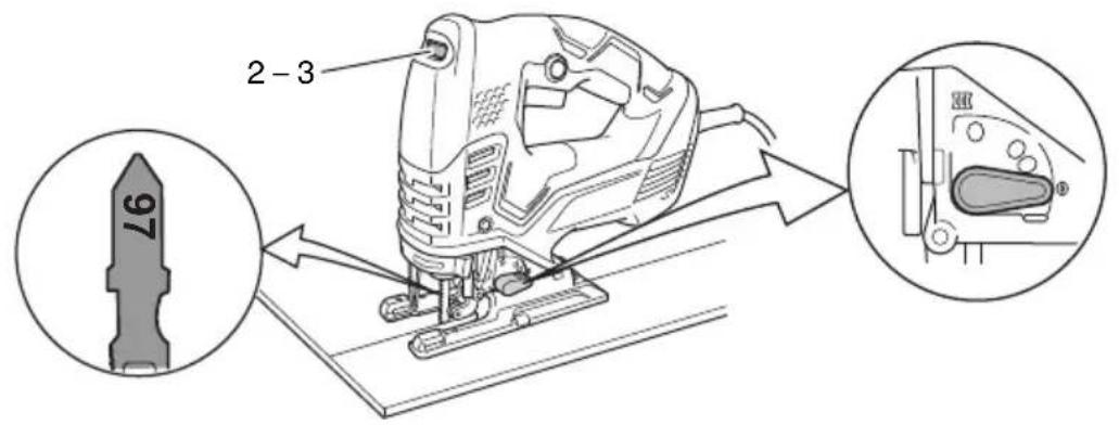
At low speed (dial setting: 1 or 2) do not cut a wood with a thickness of more than 10 mm or metal with a thickness of more than 1 mm.
- In order to prevent blade dislodging, damage or excessive wear on the plunger, please make sure to have surface of the base plate attached to the work piece while sawing.
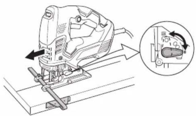
- To ensure accurate cutting when using the guide (Fig. 13), always set the orbital position to "0".
- When sawing a small circular arc, reduce the feeding speed of the machine. If the machine is fed too fast, it could cause the blade to break.
- Circular cutting must be done with the blade approximately vertical to the bottom surface of the base.
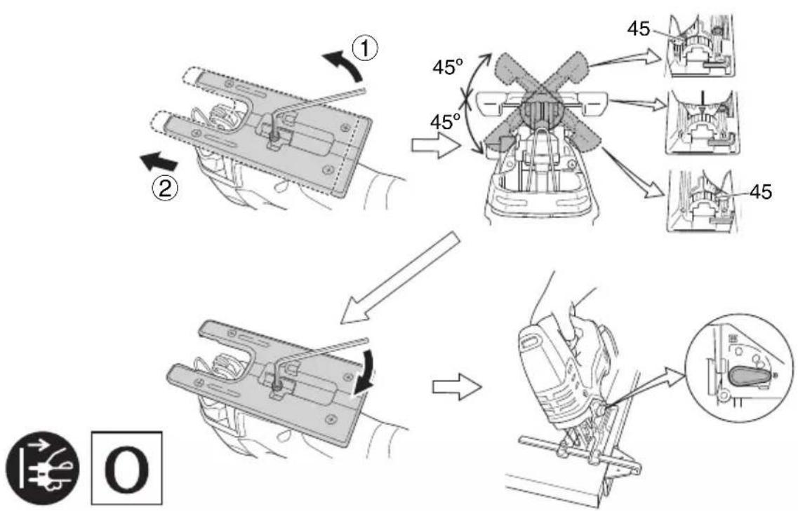
- Angular cutting can not be done when adopting dust collector.
- RCD
The use of a residual current device with a rated residual current of 30 mA or less at all times is recommended.
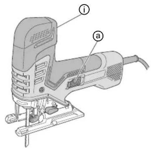
NAMES OF PARTS (Fig. 1 – Fig. 18)
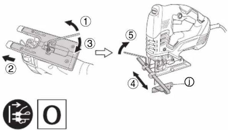
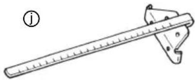
| a | Switch | j | Guide |
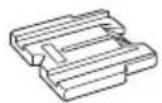
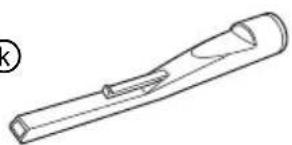
| b | Lever | k | Dust collector |
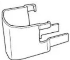
| c | Plunger | l | Chip cover |
| d | Blade holder | m | Wood screw / Nail |
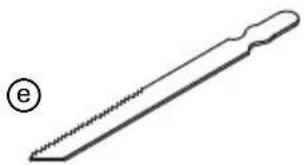
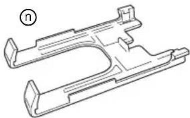
| e | Blade | n | Sub base |
| f | Roller | p | Hexagonal bar wrench |
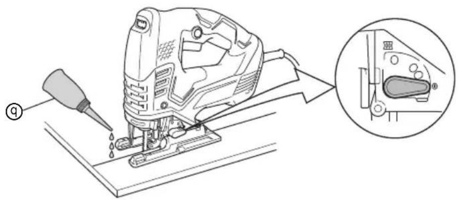
| g | Base | q | Oiler |
| h | Base plate | r | Splinter guard |
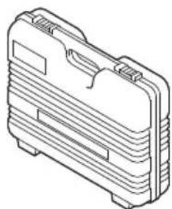
| i | Dial | s | Case |
SYMBOLS
WARNING
The following show symbols used for the machine.
Be sure that you understand their meaning before use.
 | CJ160V / CJ160VA : Jig saw |
 | |
 | To reduce the risk of injury, user must read instruction manual. |
 | Only for EU countriesDo not dispose of electric tools together with household waste material!In observance of European Directive 2012/19/EU on waste electrical and electronic equipment and its implementation in accordance with national law, electric tools that have reached the end of their life must be collected separately and returned to an environmentally compatible recycling facility. |
| V | Rated voltage |
| ~ | Alternating current |
| P | Power input |
| n_0 | No-load speed |
 | Weight(According to EPTA-Procedure 01/2014) |
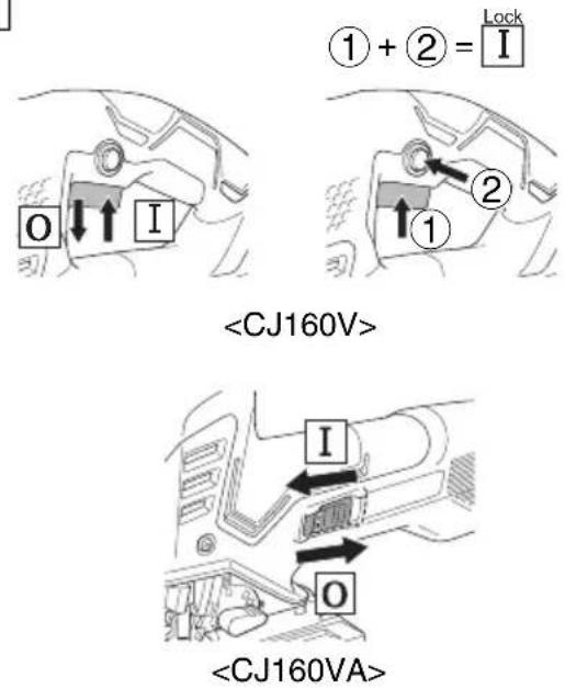
| I | Switching ON |
 | Switching OFF |
 | Disconnect mains plug from electrical outlet |
 | Class II tool |
STANDARD ACCESSORIES
In addition to the main unit (1 unit), the package contains the accessories listed in the below.
○ Blades (No. 41, No. 123X) ....1 each
No. 41: Refer to Table 1
No. 123X: Mild steel plate 1.5 – 10 mm
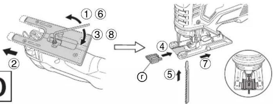
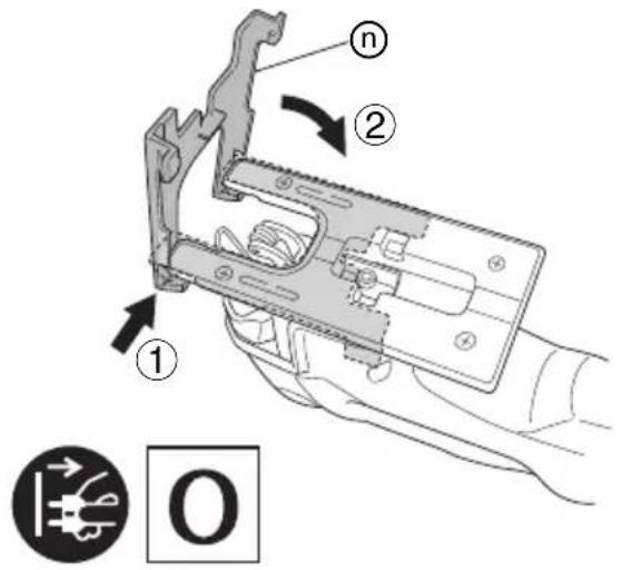
○ Sub base ....1
○ Hexagon bar wrench ....1
○ Splinter guard....1
○ Dust collector ....1
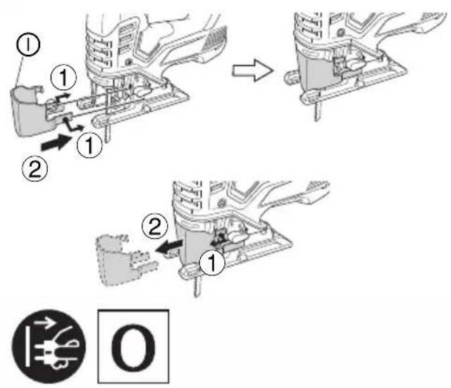
○ Chip cover ....1
Standard accessories are subject to change without notice.
APPLICATIONS
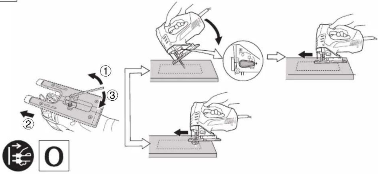
○ Cutting various lumber and pocket cutting
○ Cutting mild steel plate, aluminum plate, and copper plate
○ Cutting synthetic resins, such as phenol resin and vinyl chloride
○ Cutting thin and soft construction materials
○ Cutting stainless steel plate (with No. 97 blade)
SPECIFICATIONS
| Voltage (by areas)*1 | (110 V, 120 V, 220 V, 230 V, 240 V) ~ |
| Power Input*1 800 W | |
| Max. cutting depth | Wood 160 mmMild steel 10 mm |
| No-load speed*1 800 – 2800 | min -1 |
| Stroke 26 mm | |
| Min. cutting radius 25 mm | |
| Weight*2 | 2.7 kg (CJ160V),2.6 kg (CJ160VA) |
*1 Be sure to check the nameplate on product as it is subject to change by areas.
*2 Weight: According to EPTA-Procedure 01/2014
NOTE
Due to HiKOKI's continuing program of research and development, the specifications herein are subject to change without prior notice.
MOUNTING AND OPERATION
| Action | Figure | Page |
| Changing blades | 2 | 113 |
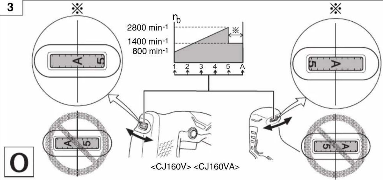
| Adjusting the blade operating speed*1 | 3 | 113 |
| Switch operation 4 | 114 | |
| How to use the LED light | 5 | 114 |
| Adjusting the orbital operation | 6 | 114 |
| Splinter guard | 7 | 114 |
| Sub base*2 | 8 | 115 |
| Chip cover | 9 | 115 |
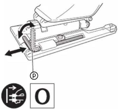
| Housing the hexagonal bar wrench | 10 | 115 |
| Mounting the guide | 11 | 115 |
| Rectilinear cutting | 12 | 115 |
| Cutting a circle or a circular arc | 13 | 115 |
| Cutting metallic materials | 14 | 116 |
| Angular cutting | 15 | 116 |
| Pocket cutting | 16 | 116 |
| Concerning cutting of stainless steel plates | 17 | 117 |
| Connecting with cleaner 18 | 117 | |
| Selecting accessories | — | 118 |
*1 The tool is equipped with two modes: "Standard Mode" and "AUTO Mode".
(1) Standard Mode
You can change the blade operating speed between 800 to 2800 min-1 by adjusting the dial from "1" to "5".
(2) AUTO Mode
Depending on the workload, AUTO Mode "A" will automatically change the blade operating speed to 1400 min-1 or 2800 min-1. This has the effect of lowering vibration and noise prior to and during operation.
Adjust the dial for the mode and speed that best suits your task conditions and materials.
Blade operating speed
| Mode | Dial | Blade operating speed |
| Standard Mode | 1 – 5800 – 2800 min ^-1 | |
| AUTO Mode | A | No load: 1400 min ^-1 With load: 2800 min-1 |
With AUTO Mode, the vibration frequency may not reach 2800 min-1 or return to 1400 min-1 depending on variables such as the type of work.
NOTE\*2
When the sub base is attached, the blade's protrusion from the material being cut will be reduced by 3mm. When the blade has been moved down to the lowest point, check to make sure that it is protruding from the material.
SELECTION OF BLADES
Accessory blades
To ensure maximum operating efficiency and results, it is very important to select the appropriate blade best suited to the type and thickness of the material to be cut. Three types of blades are provided as standard accessories. The blade number is engraved in the vicinity of the mounting portion of each blade. Select appropriate blades by referring to Table 1.
MAINTENANCE AND INSPECTION
1. Inspecting the blade
Continued use of a dull or damaged blade will result in reduced cutting efficiency and may cause overloading of the motor. Replace the blade with a new one as soon as excessive abrasion is noted.
2. Inspecting the mounting screws
Regularly inspect all mounting screws and ensure that they are properly tightened. Should any of the screws be loose, retighten them immediately. Failure to do so could result in serious hazard.
3. Maintenance of the motor
The motor unit winding is the very “heart” of the power tool. Exercise due care to ensure the winding does not become damaged and/or wet with oil or water.
4. Inspecting the carbon brushes
For your continued safety and electrical shock protection, carbon brush inspection and replacement on this tool should ONLY be performed by a HiKOKI AUTHORIZED SERVICE CENTER.
5. Replacing supply cord
If the supply cord of Tool is damaged, the Tool must be returned to HiKOKI Authorized Service Center for the cord to be replaced.
CAUTION
In the operation and maintenance of power tools, the safety regulations and standards prescribed in each country must be observed.
GUARANTEE
We guarantee HiKOKI power tools in accordance with statutory/country specific regulation. This guarantee does not cover defects or damage due to misuse, abuse, or normal wear and tear. In case of complaint, please send the power tool, undismantled, with the GUARANTEE CERTIFICATE found at the end of this Handling instruction, to a HiKOKI Authorized Service Center.
IMPORTANT
Correct connection of the plug
The wires of the main lead are coloured in accordance with the following code:
Blue: — Neutral
Brown: — Live
As the colours of the wires in the main lead of this tool may not correspond with the coloured markings identifying the terminals in your plug proceed as follows:
The wire coloured blue must be connected to the terminal marked with the letter N or coloured black. The wire coloured brown must be connected to the terminal marked with the letter L or coloured red. Neither core must be connected to the each terminal.
NOTE:
This requirement is provided according to BRITISH STANDARD 2769: 1984.
Therefore, the letter code and colour code may not be applicable to other markets except The United Kingdom.
Information concerning airborne noise and vibration
The measured values were determined according to EN62841 and declared in accordance with ISO 4871.
Measured A-weighted sound power level:
95 dB (A) (CJ160V)
96 dB (A) (CJ160VA)
Measured A-weighted sound pressure level:
84 dB (A) (CJ160V)
85 dB (A) (CJ160VA)
Uncertainty K: 5 dB (A).
Wear hearing protection.
Vibration total values (triax vector sum) determined according to EN62841.
Cutting boards:
Vibration emission value a_h , B = 9.0 m/s ^2 (CJ160V)
9.5 m/s²(CJ160VA)
Uncertainty K = 1.5 m/s²
Cutting sheet metal:
Vibration emission value a_h , M = 4.9 m/s (CJ160V)
7.0 m/s²(CJ160VA)
Uncertainty K = 1.5 m/s ^4
The declared vibration total value has been measured in accordance with a standard test method and may be used for comparing one tool with another.
It may also be used in a preliminary assessment of exposure.
WARNING
☐ The vibration emission during actual use of the power tool can differ from the declared total value depending in the ways in which the tool is used.
- Identify safety measures to protect the operator that are based on an estimation of exposure in the actual conditions of use (taking account of all parts of the operating cycle such as the times when the tool is switched off and when it is running idle in addition to the trigger time).
NOTE
Due to HiKOKI's continuing program of research and development, the specifications herein are subject to change without prior notice.
Table 1 List of appropriate blades
| Material to be cut | Blade Material quality | No. 1 (Super long) | No. 11 No. 12 No. | 15 No. 16 | No. 21 No. 22 No. 4 | 1 No. 97 | ||||
| Thickness of material (mm) | ||||||||||
| Lumber | General lumber | Below 135 | 10 - 55 | Below 20 | 10 - 55 5 - 40 | 10 - 65 | ||||
| Plywood 5 - 30 Below 10 5 - 30 3 - 20 | ||||||||||
| Iron plate | Mild steel plate 3 - 6 Below 3 2 - 5 | |||||||||
| Stainless steel plate | 1.5 - 2.5 | |||||||||
| Nonferrous metal | Aluminium copper, brass | 3 - 12 Below 3 Below 5 | ||||||||
| Aluminium sash | Height up to 25 | Height up to 25 | ||||||||
| Plastics | Phenol resin, melamine, resin, etc. | 5 - 20 Below 6 5 - 15 Below 6 5 - 15 | ||||||||
| Vinyl chloride, acryl resin, etc. | 5 - 30 Below 10 5 - 20 Below 5 5 - 30 3 - 20 5 - 15 | |||||||||
| Foamed polyethylene, foamed styrol | 10 - 55 3 - 25 5 - 25 3 - 25 10 - 55 3 - 40 5 - 25 | |||||||||
| Pulp | Card board, corrugated paper | 10 - 55 3 - 25 10 - 55 3 - 40 | ||||||||
| Hardboard | 3 - 25 Below 6 | 3 - 25 | ||||||||
| Fiberboard | Below 6 | |||||||||
NOTE
The minimum cutting radius of No. 1 (Super long), No. 21, No. 22 and No. 41 blades is 100 mm.
VEILIGHEIDSWAARSCHUWINGEN DECOUPEERZAAG
VEILIGHEIDSWAARSCHUWINGEN
VEDLIKEHOLD OG INSPEKSJON
1. Inspisere bladet
Fortsatt bruk av et sløvt eller skadet blad vil føre til redusert skjæreeff aktivitet og kan føre til overbelastning av motoren. Bytt bladet med et nytt ett med en gang overdreven avsliping er merkbart.
2. Inspisere monteringsskruene
○ Biçaklar (No. 41, No. 123X) ...... Her birinden 1 adet No. 41: Bkz. Tablo 1
No. 123X: Yumuşak çelik levha 1,5 – 10 mm
○ Ikinci taban....1
○ Alyan anahtarı....1
2


flowchart
graph TD
    A["Start"] --> B{Speed Limit}
    B --> C["1: 2800 min⁻¹"]
    B --> D["2: 1400 min⁻¹"]
    B --> E["3: 800 min⁻¹"]
    F["Start"] --> G{Speed Limit}
    G --> H["1: 2800 min⁻¹"]
    G --> I["2: 1400 min⁻¹"]
    G --> J["3: 800 min⁻¹"]
    K["Start"] --> L{Speed Limit}
    L --> M["1: 2800 min⁻¹"]
    L --> N["2: 1400 min⁻¹"]
    L --> O["3: 800 min⁻¹"]
    P["Start"] --> Q{Speed Limit}
    Q --> R["1: 2800 min⁻¹"]
    Q --> S["2: 1400 min⁻¹"]
    Q --> T["3: 800 min⁻¹"]
    U["Start"] --> V{Speed Limit}
    V --> W["1: 2800 min⁻¹"]
    V --> X["2: 1400 min⁻¹"]
    V --> Y["3: 800 min⁻¹"]
    Z["Start"] --> AA{Speed Limit}
    AA --> AB["1: 2800 min⁻¹"]
    AA --> AC["2: 1400 min⁻¹"]
    AA --> AD["3: 800 min⁻¹"]
    AE["Start"] --> AF{Speed Limit}
    AF --> AG["1: 2800 min⁻¹"]
    AF --> AH["2: 1400 min⁻¹"]
    AF --> AI["3: 800 min⁻¹"]
    AJ["Start"] --> AK{Speed Limit}
    AK --> AL["1: 2800 min⁻¹"]
    AK --> AM["2: 1400 min⁻¹"]
    AK --> AN["3: 800 min⁻¹"]
    AO["Start"] --> AP{Speed Limit}
    AP --> AQ["1: 2800 min⁻¹"]
    AP --> AR["2: 1400 min⁻¹"]
    AP --> AS["3: 800 min⁻¹"]
    AT["Start"] --> AU{Speed Limit}
    AU --> AV["1: 2800 min⁻¹"]
    AU --> AW["2: 1400 min⁻¹"]
    AU --> AX["3: 800 min⁻¹"]
    AY["Start"] --> AZ{Speed Limit}
    AZ --> BA["1: 2800 min⁻¹"]
    AZ --> BB["2: 1400 min⁻¹"]
    AZ --> BC["3: 800 min⁻¹"]
    BD["Start"] --> BE{Speed Limit}
    BE --> BF["1: 2800 min⁻¹"]
    BE --> BG["2: 1400 min⁻¹"]
    BE --> BH["3: 800 min⁻¹"]
    BI["Start"] --> BJ{Speed Limit}
    BJ --> BK["1: 2800 min⁻¹"]
    BJ --> BL["2: 1400 min⁻¹"]
    BJ --> BM["3: 800 min⁻¹"]
    BN["Start"] --> BO{Speed Limit}
    BO --> BP["1: 2800 min⁻¹"]
    BO --> BQ["2: 1400 min⁻¹"]
    BO --> BR["3: 800 min⁻¹"]
    BS["Start"] --> BT{Speed Limit}
    BT --> BU["1: 2800 min⁻¹"]
    BT --> BV["2: 1400 min⁻¹"]
    BT --> BW["3: 800 min⁻¹"]
    BX["Start"] --> BY{Speed Limit}
    BY --> CA["1: 2800 min⁻¹"]
    BY --> CB["2: 1400 min⁻¹"]
    BY --> CC["3: 800 min⁻¹"]
    CD["Start"] --> CE{Speed Limit}
    CE --> CF["1: 2800 min⁻¹"]
    CE --> CG["2: 1400 min⁻¹"]
    CE --> DH["3: 800 min⁻¹"]
    DI["Start"] --> DJ{Speed Limit}
    DJ --> DE["1: 2800 min⁻¹"]
    DJ --> DF["2: 1400 min⁻¹"]
    DJ --> DG["3: 800 min⁻¹"]
    DH --> DH
    DE --> DH
    DE --> DH
    DE --> DH
    DE --> DH
    DE --> DH
    DE --> DH
    DE --> DH
    DE --> DH
    DE --> DH
    DE --> DH
    DE --> DH
    DE --> DH
    DE --> DH
    DE --> DH
    DE --> DH
    DE --> DH
    DE --> DH
    DE --> DH
    DE --> DH
    DE --> DH
    CE --> DV{Condition}
    DV --> DW["CJ160V > <CJ160VA>"]
4
5
6

7
natural_image
Diagram showing a mechanical or structural change between two circular components, one with spring-like elements and the other with a rectangular block (no text or symbols)

8
9
10 11
12 13
natural_image
Diagram of a manual push tool with an inset showing the internal mechanism (no text or symbols present)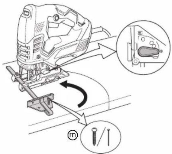
14
15
16
flowchart
graph TD
    A["Cut the cutter into part"] --> B["Step 1: Cutting down"]
    B --> C["Step 2: Cutting down"]
    C --> D["Step 3: Cutting down"]
    D --> E["Step 4: Cutting down"]
    E --> F["Step 5: Cutting down"]
    F --> G["Step 6: Cutting down"]
17
18
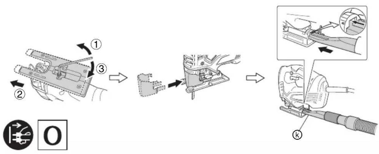
flowchart
graph TD
    A["Disassembly of switch"] --> B["Assembly"]
    B --> C["Final Installation with Component k"]
natural_image
Simple line drawing of a diagonal saw blade with a handle, labeled (e) in the corner (no text or symbols on the blade itself)*
| 1 321878 |
| 11 879336 |
| 12 879337 |
| 15 879338 |
| 16 879339 |
| 21 879340 |
| 22 879341 |
| 41 879357 |
| 97 963400 |
p

944458
natural_image
Line drawing of a ruler with measurement markings and a pointer (no text or symbols)879391
r
338997
k
natural_image
Line drawing of a cylindrical object with a curved handle and a small protrusion, no text or symbols present.370492
natural_image
Technical line drawing of a mechanical bracket component (no text or symbols)339018
①
natural_image
Line drawing of a mechanical component with no text or symbols338996
S
natural_image
Line drawing of a mechanical component with multiple slots and mounting feet (no text or symbols)| English Dansk Română | ||||
| GUARANTEE CERTIFICATE1 Model No.2 Serial No.3 Date of Purchase4 Customer Name and Address5 Dealer Name and Address(Please stamp dealer name and address) | GARANTIBEVIS1 Modelnummer2 Serienummer3 Købsdato4 Kundes navn og adresse5 Forhandlers navn og adresse(Indsæt stempel med forhandlers navn og adresse) | CERTIFICAT DE GARANTIE1 Model nr.2 Nr. de serie3 Data cumpărării4 Numele și adresa clientului5 Numele și adresa distribuitorului(Vă rugăm aplicați stampila cu numele și adresa distribuitorului) | ||
| Deutsch Norsk Slovenščina | ||||
| GARANTIESCHEIN1 Modell-Nr.2 Serien-Nr.3 Kaufdatum4 Name und Anschrift des Kunden5 Name und Anschrift des Händlers(Bitte mit Namen und Anschrift des Handlers abstempeln) | GARANTISERTIFIKAT1 Modellnr.2 Serienr.3 Kjøpsdato4 Kundens navn og adresse5 Forhandlerens navn og adresse(Vennligst stemple forhandlerens navn og adresse) | GARANCIJSKO POTRDILO1 Št. modela2 Serijska št.3 Datum nakupa4 Ime in naslov kupca5 Ime in naslov prodajalca(Prosimo vtsnite žig z imenom in naslovom prodajalca) | ||
| Français Suomi Slovenčina | ||||
| CERTIFICAT DE GARANTIE1 No. de modèle2 No de série3 Date d'achat4 Nom et adresse du client5 Nom et adresse du revendeur(Cachet portant le nom et l'adresse du revendeur) | TAKUUTODISTUS1 Malli nro2 Sarja nro3 Ostopäivämäärä4 Asiakkaan nimi ja osoite5 Myyjän nimi ja osoite(Leimaa myyjän nimi ja osoite) | ZÁRUČNÝ LISTA1 Č. modelu2 Sériové č.3 Dátum zakúpenia4 Meno a adresa zákazníka5 Názov a adresa predajcu(Pečiatka s názvom a adresou predajcu) | ||
| Italiano Ελλημικά Βългарски | ||||
| CERTIFICATO DI GARANZIA1 Modello2 N° di serie3 Data di acquisto4 Nome e indirizzo dell'acquirente5 Nome e indirizzo del rivenditore(Si prega di apporre il timbro con questi dati) | ПІЗТОПОІНТИКО ЕГГУНЄНЗ1 Ap. Movтėlou2 Aŭξων Ap.3 Нμερομηνία αγοράς4 ́Овома кαι διεύθυνση πελάτη5 ́Овома кαι διεύθυνση μεταπωλητή(Πορακαλούμε να χρησιμοποιηθεί σφραγίδα) | ГАРАНЦИОНЕН СЕРТИФИКАТ1 Модел No2 Сериен No3 Дата за закупуване4 Име и адрес на клиента5 Име и адрес на търговеца(Моля, отпечатайте името и адрес на дилъра) | ||
| Nederlands Polski Srpski | ||||
| GARANTIEBEWIJS1 Modelnummer2 Serienummer3 Datum van aankoop4 Naam en adres van de gebruiker5 Naam en adres van de handelaar(Stempel a.u.b. naam en adres vande de handelaar) | GWARANCJA1 Model2 Numer seryjny3 Data zakupu4 Nazwa klienta i adres5 Nazwa dealera i adres(Pieczęć punktu sprzedaży) | GARANTNI SERTIFIKAT1 Br. modela.2 Serijski br.3 Datum kupovine4 Ime i adresa kupca5 Ime i adresa prodavca(Molimo da stavite pečat na ime i adresu trgovca) | ||
| Español Magyar Hrvatski | ||||
| CERTIFICADO DE GARANTÍA1 Número de modelo2 Número de serie3 Fecha de adquisición4 Nombre y dirección del cliente5 Nombre y dirección del distribuidor(Se ruega poner el sello del distribuidor con su nombre y dirección) | GARANCIA BIZONYLAT1 Típusszám2 Sorozatszám3 A vásárlás dátuma4 A Vásárló neve és címe5 A Kereskedő neve és címe(Kérjük ide elhelyezni a Kereskedő nevének és címének pecsétjét) | JAMSTVENI CERTIFIKAT1 Br modela.2 Serijski br.3 Datum kupnje4 Ime i adresa kupca5 Ime i adresa trgovca(Molimo stavite pečat na ime i adresu trgovca) | ||
| Português Češťina | ||||
| CERTIFICADO DE GARANTIA1 Número do modelo2 Número do série3 Data de compra4 Nome e morada do cliente5 Nome e morada do distribuidor(Por favor, carimbe o nome e morada do distribuidor) | ZÁRUČNÍ LIST1 Model č.2 Série č.3 Datum nákupu4 Jméno a adresa zákazníka5 Jméno a adresa prodejce(Prosíme o razitko se jménem a adresou prodejce) | |||
| Svenska Türkçe | ||||
| GARANTICERTIFIKAT1 Modellnr2 Serienr3 Inköpsdatum4 Kundens namn och adress5 Försäljarens namn och adress(Stämpla försäljarens namn och adress) | GARANTÍ SERTÍFÍKASI1 Model No.2 Seri No.3 Satin Alma Tarihi4 Müşteri Adı ve Adresi5 Bayi Adı ve Adresi(Lütfen bayi adini ve adresini kaşe olarak basin) | |||

HiKOKI
| 1 | |
| 2 | |
| 3 | |
| 4 | |
| 5 |
Siemensring 34, 47877 willich, Germany
Tel: +49 2154 49930
Fax: +49 2154 499350
URL: http://www.hikoki-powertools.de
Hikoki Power Tools Netherlands B.V.
Brabanthaven 11, 3433 PJ Nieuwegein, The Netherlands
Tel: +31 30 6084040
Fax: +31 30 6067266
URL: http://www.hikoki-powertools.nl
Hikoki Power Tools (U.K.) Ltd.
Precedent Drive, Rooksley, Milton Keynes, MK 13, 8PJ,
United Kingdom
Tel: +44 1908 660663
Fax: +44 1908 606642
URL: http://www.hikoki-powertools.uk
Hikoki Power Tools France S.A.S.
Hikoki Power Tools Belgium N.V./S.A.
Koningin Astridlaan 51, B-1780 Wemmel, Belgium
Tel: +32 2 460 1720
Fax: +32 2 460 2542
URL http://www.hikoki-powertools.be
Hikoki Power Tools Italia S.p.A
Via Piave 35, 36077, Altavilla Vicentina (VI), Italy
Tel: +39 0444 548111
Fax: +39 0444 548110
URL: http://www.hikoki-powertools.it
Hikoki Power Tools Ibérica, S.A.
C/ Puigbarral, 26-28, Pol. Ind. Can Petit, 08227 Terrassa
(Barcelona), Spain
Tel: +34 93 735 6722
Fax: +34 93 735 7442
URL: http://www.hikoki-powertools.es
Kjeller Vest 7, N-2007 Kjeller, Norway
Tel: (+47) 6692 6600
Fax: (+47) 6692 6650
URL: http://www.hikoki-powertools.no
Hikoki Power Tools Sweden AB
Rotebergsvagen 2B SE-192 78 Sollentuna, Sweden
Tel: (+46) 8 598 999 00
Fax: (+46) 8 598 999 40
URL: http://www.hikoki-powertools.se
Hikoki Power Tools Denmark A/S
Lillebaeltsvej 90, 6715 Esbjerg N, Denmark
Tel: (+45) 75 14 32 00
Fax: (+45) 75 14 36 66
URL: http://www.hikoki-powertools.dk
Hikoki Power Tools Finland Oy
Tupalankatu 9, 15680 Lahti, Finland
Tel: (+358) 20 7431 530
Fax: (+358) 20 7431 531
URL: http://www.hikoki-powertools.fi
Hikoki Power Tools Hungary Kft.
Hikoki Power Tools Romania S.R.L.
Ring Road, No. 66, Mustang Traco Warehouses, Warehouse
No.1, Pantelimon City, 077145, Ilfov County, Romania

- (Original instructions)
- GENERAL POWER TOOL SAFETY WARNINGS
- WARNING
- 1) Work area safety
- 2) Electrical safety
- 3) Personal safety
- 4) Power tool use and care
- 5) Service
- PRECAUTION
- JIG SAW SAFETY WARNINGS
- ADDITIONAL SAFETY WARNINGS
- NAMES OF PARTS (Fig. 1 – Fig. 18)
- SYMBOLS
- STANDARD ACCESSORIES
- APPLICATIONS
- NOTE
- NOTE\*2
- SELECTION OF BLADES
- Accessory blades
- MAINTENANCE AND INSPECTION
- Inspecting the blade
- Inspecting the mounting screws
- Maintenance of the motor
- Inspecting the carbon brushes
- Replacing supply cord
- CAUTION
- GUARANTEE
- IMPORTANT
- NOTE:
- Information concerning airborne noise and vibration
- VEILIGHEIDSWAARSCHUWINGEN DECOUPEERZAAG
- VEILIGHEIDSWAARSCHUWINGEN
- VEDLIKEHOLD OG INSPEKSJON
- Inspisere bladet
- Inspisere monteringsskruene
- Hikoki Power Tools Netherlands B.V.
- Hikoki Power Tools (U.K.) Ltd.
- Hikoki Power Tools France S.A.S.
- Hikoki Power Tools Belgium N.V./S.A.
- Hikoki Power Tools Italia S.p.A
- Hikoki Power Tools Ibérica, S.A.
- Hikoki Power Tools Sweden AB
- Hikoki Power Tools Denmark A/S
- Hikoki Power Tools Finland Oy
- Hikoki Power Tools Hungary Kft.
- Hikoki Power Tools Romania S.R.L.
Brand : HiKOKI
Model : CJ160VA
Category : Saw