
IS 3180 COM1 - Motion detector STEINEL - Free user manual and instructions
Find the device manual for free IS 3180 COM1 STEINEL in PDF.
User questions about IS 3180 COM1 STEINEL
0 question about this device. Answer the ones you know or ask your own.
Ask a new question about this device
Download the instructions for your Motion detector in PDF format for free! Find your manual IS 3180 COM1 - STEINEL and take your electronic device back in hand. On this page are published all the documents necessary for the use of your device. IS 3180 COM1 by STEINEL.
USER MANUAL IS 3180 COM1 STEINEL
natural_image
World map silhouette in grayscale, showing continents and oceans without any text or labelsContact
www.steinel.de/contact

110073034 10/2019_A Technische Änderungen vorbehalten. / Subject to technical modification without notice.


GB....26 Follow written instructions!
natural_image
Three technical line drawings of mechanical parts, including a hexagonal nut, a circular component, and a curved housing (no text or symbols)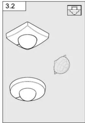
natural_image
Three technical line drawings of a mechanical component or housing, showing front, side, and top views (no text or symbols)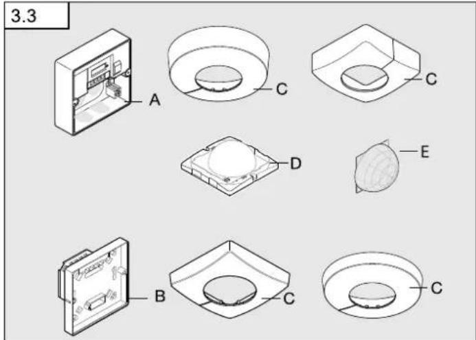
flowchart
graph TD
    subgraph ①
        A1["L"] --> B1["Switch"]
        B1 --> C1["L L ↓ N N N ⊕"]
        C1 --> D1["PE⊕"]
        E1["N"] --> F1["Switch"]
        F1 --> G1["L L ↓ N N N ⊕"]
        G1 --> H1["PE⊕"]
        I1["L"] --> J1["Switch"]
        J1 --> K1["L L ↓ N N N ⊕"]
        K1 --> L1["PE⊕"]
        M1["N"] --> N1["Switch"]
        N1 --> O1["L L ↓ N N N ⊕"]
        O1 --> P1["PE⊕"]
        Q1["PE⊕"] --> R1["PE⊕"]
    end
    subgraph ②
        S1["L"] --> T1["Switch"]
        T1 --> U1["L L ↓ N N N ⊕"]
        U1 --> V1["PE⊕"]
        W1["N"] --> X1["Switch"]
        X1 --> Y1["PE⊕"]
        Z1["PE⊕"] --> AA1["PE⊕"]
        AB1["L"] --> AC1["Switch"]
        AC1 --> AD1["L L ↓ N N N ⊕"]
        AD1 --> AE["PE⊕"]
        AF1["N"] --> AG1["Switch"]
        AG1 --> AH1["PE⊕"]
        AI2["L"] --> AJ1["Switch"]
        AJ1 --> AK1["L L ↓ N N N ⊕"]
        AK1 --> AL["PE⊕"]
        AM2["PE⊕"] --> AN2["PE⊕"]
    end
    subgraph ③
        AO["L"] --> AP["Switch"]
        AP --> AQ["LL ↓ N N N ⊕"]
        AQ --> AR["PE⊕"]
        AS["L"] --> AT["Switch"]
        AT --> AU["L L ↓ N N N ⊕"]
        AU --> AV["PE⊕"]
        AW["PE⊕"] --> AX["PE⊕"]
    end
    subgraph ④
        A2["L"] --> AZ["Switch"]
        AZ --> BA["L L ↓ N N N ⊕"]
        BA --> BB["PE⊕"]
        BC["PE⊕"] --> BD["PE⊕"]
6
flowchart
graph TD
    A["Light fixture placement"] --> B["Top Floor"]
    B --> C["Top Floor with 2.5x 100% coverage"]
    C --> D["Top Floor with 2.5x 100% coverage"]
    D --> E["Bottom Floor with circular opening"]
    E --> F["Bottom Floor with circular opening"]
    style A fill:#f9f,stroke:#333
    style F fill:#bbf,stroke:#333
7
8
9
flowchart
graph TD
    A["Device 6.1"] --> B{Status}
    B -->|Yes| C["2-1000 Lux"]
    B -->|No| D["5 s - 15 min"]
    C --> E["Time: min, max"]
    D --> F["Time: min, max"]
DE
- Please read carefully and keep in a safe place.
- Undercopyright.
Reproduction either in whole or in part only with our consent. - Subject to change in the interest of technical progress.
Symbols

Hazard warning!

Reference to other information in the document.
2. General safety precautions

Disconnect the power supply before attempting any work on the sensor.
- During installation, the electric power cable to be connected must not be live. Therefore, switch off the power first and use a voltage tester to make sure the wiring is off-circuit.
- Installing the sensor involves work on the mains power supply. This work must therefore be carried out professionally in accordance with national wiring regulations and electrical operating conditions. ((DE- VDE 0100, AT- ÖVE-EN 1, CH- SEV 1000)
3. IS 3360, IS 3360 MX, IS 345, IS 3180 COM1
Proper use
- IS 3360 MX and IS 345 MX are suitable for indoor ceiling mounting.
– IS 3360 MX and IS 345 MX are suitable for indoor- and outdoor ceiling mounting. - IS 3180 is suitable for wall mounting indoors and outdoors.
- The concealed versions are only suitable for installing indoors.
The motion detector is equipped with pyro sensors that detect the invisible heat emitted from moving objects (people, animals etc.). The heat detected in this way is converted electronically into a signal that switches a connected load ON (e.g. a light). Heat is not detected through obstacles, such as walls or panes of glass. Heat radiation of this type will, therefore, not trigger the sensor.
Optionally, all function settings can be made via the RC5, RC8 remote controls as well as the Smart Remote. (→ "7. Accessories")
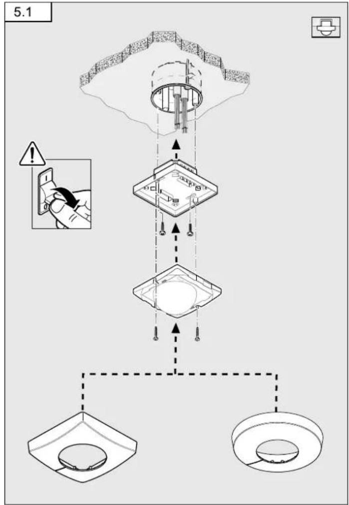
Package contents for concealed installation (Fig. 3.1)
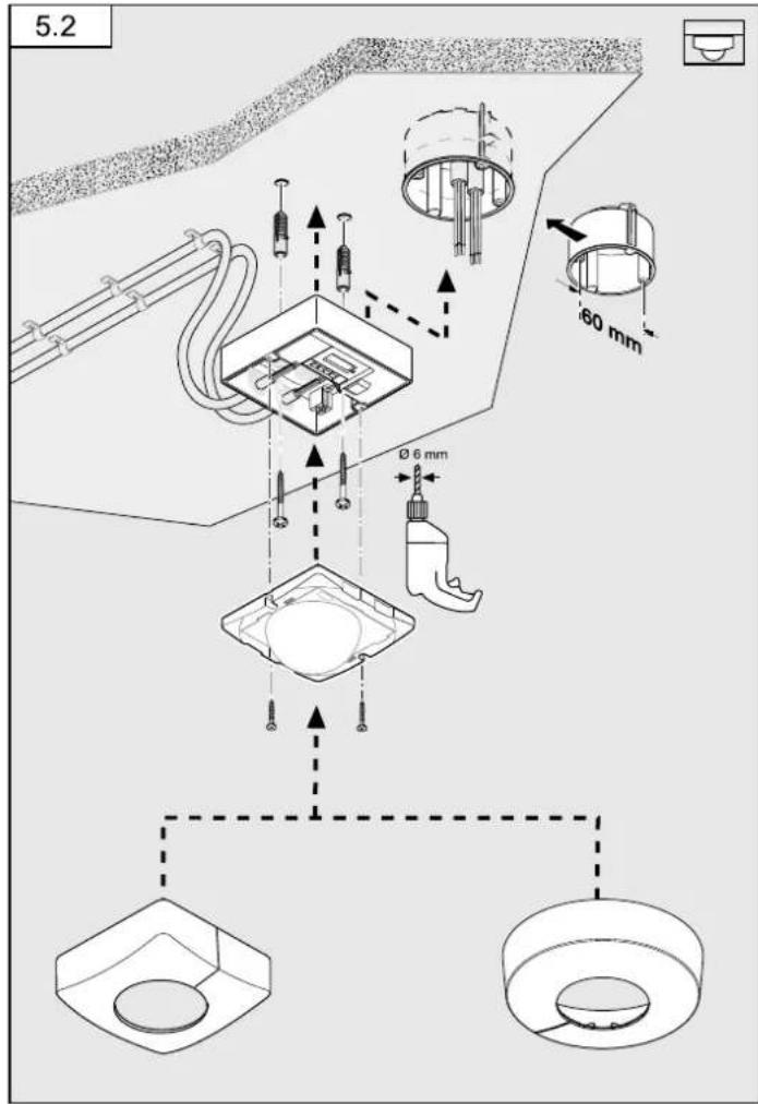
Package contents for surface-mounted installation (Fig. 3.2)
Product components (Fig. 3.3)
A Load module, power supply lead, surface-mounted
B Load module, power supply lead, concealed installation
C Designer trim, round or square
D Sensor module
E Half-round clip-on shroud
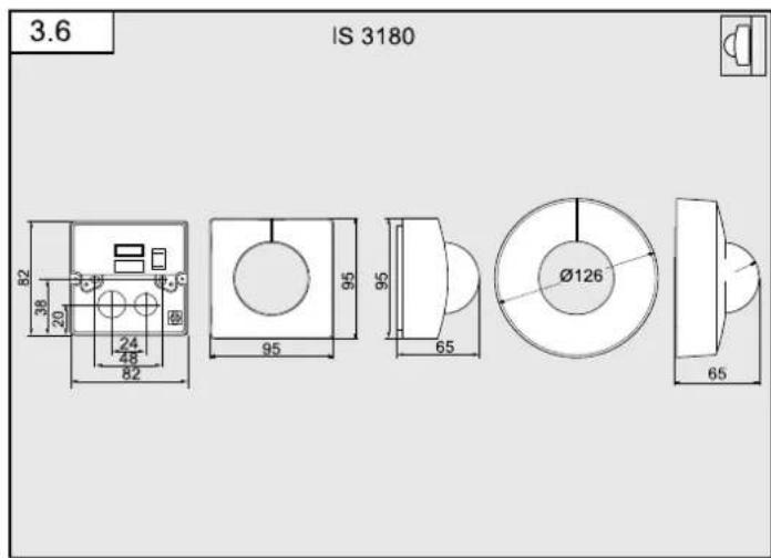
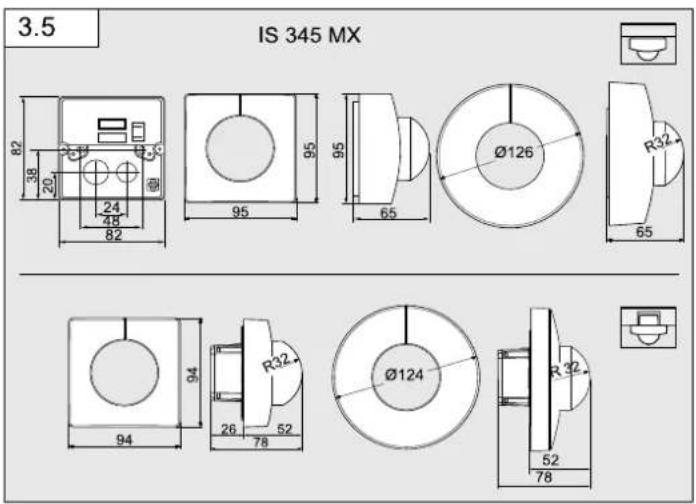
Product dimensions
Surface-mounted / concealed (Fig. 3.4)
IS 3360 IS, IS 3360 MX, IS 345
Surface-mounted / concealed (Fig. 3.5)
IS 345 MX
Surface-mounted / wall-mounted (Fig. 3.6)
IS 3180
4. Electrical installation
The mounting location should be at least 50 cm away from other lights because heat radiated from these may activate the system.
An optional corner wall mount (product no. 648015 black or 035174 white) is available for mounting the IS 3180.
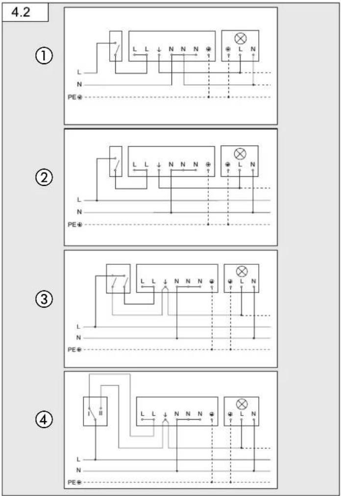
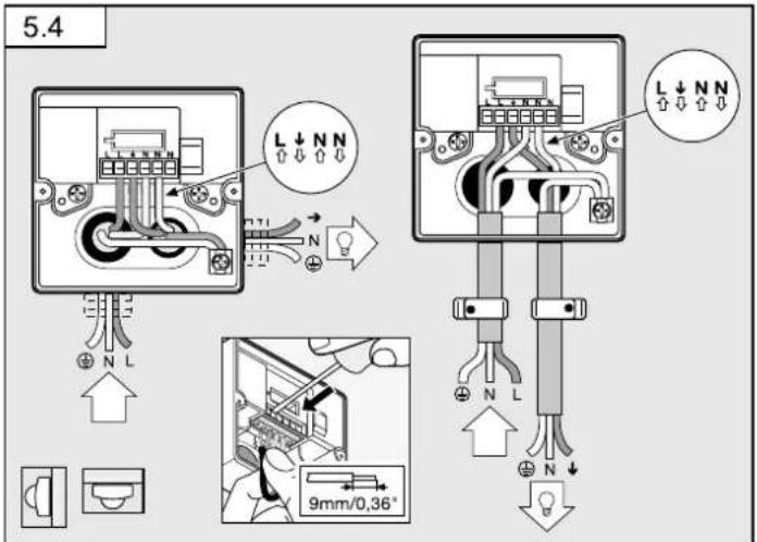
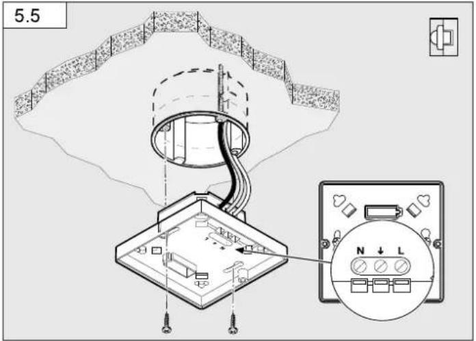
The supply lead consist of three wires:
L = phase conductor (usually black, brown or grey)
N = neutral conductor (usually blue)
PE = protective-earth conductor (green/yellow)
↓ = switched phase conductor (usually black, brown or grey)
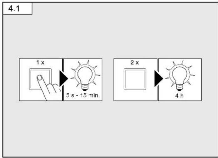
Note on manual override function (Fig. 4.1):
A power switch for switching ON and OFF can be installed in the mains supply lead. This is a prerequisite for the manual override function ( "6. Function")
If the rubber seal is damaged, the cable entry openings must be sealed with an M16 or M20 (at least IP 54) double seal cable gland.
For mounting the IS 3180 on the wall, a condensation water drainage hole ( 5 mm drill bit) is marked next to the rubber seal. This must be opened if necessary.
Connection examples (Fig. 4.2)
① Light without neutral conductor
② Light with neutral conductor
③ Connection by means of two-circuit single-interruption switch for manual and automatic operation
④ Connection via two-way switch for manual override and automatic operation
Setting I: Automatic operation
Setting II: Manual operation, light permanently ON
Note:
The system cannot be switched OFF, it is only possible to select operation via setting I or II.
a) Load, lighting max. 2000 W (refer to Technical specifications)
b) Sensor connection terminals
c) Indoor switch
d) Indoor two-circuit single-interruption switch, manual, automatic
e) Indoor two-way switch, automatic, light permanently ON
Connecting several sensors in parallel (not illustrated)
In this case, it is important not to exceed a sensor's maximum connected rating. In addition, all units must be connected to the same phase. As many as 10 sensors can be connected in parallel.
Note:
The cable between two sensors must be no more than 50 m in length.
5. Mounting
- Check all components for damage.
- Do not use the product if it is damaged.
- Select an appropriate mounting location, taking the reach and motion detection into consideration.
Procedure for installing concealed power supply lead (Fig. 5.1)
Procedure for installing surface-mounted power supply lead (Fig. 5.2) IS 3360, IS 3360 MX Highbay, IS 345, IS 345 Highbay
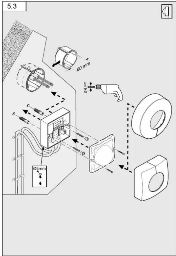
Procedure for installing concealed power supply lead (wall mounting) IS 3180 (Fig. 5.3)
- Switch OFF power supply.
- Detach designer trim from sensor module.
- Disconnect sensor module from the load module.
- Connect to mains power supply
– Surface-mounted power supply lead (Fig. 5.4)
Concealed power supply lead (Fig. 5.5)
- Insert fastening screw and mount load module.
Limiting reach
The detection zone can be optimised to suit requirements.
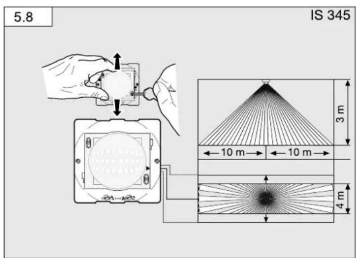
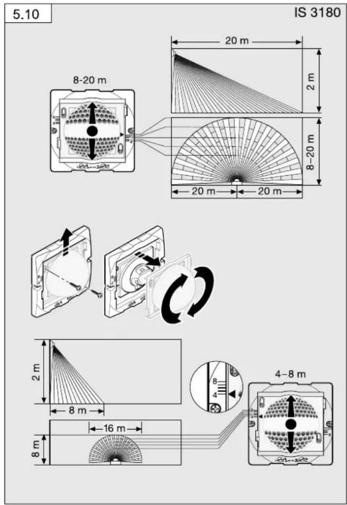
-By adjusting the lens. (Fig. 5.8 / 5.10)
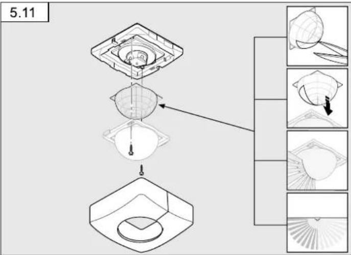
- By using the half-round clip-on shroud. (Fig. 5.11)
Note:
To limit reach, the sensor module must be detached from the load module.
• To activate the required reach, undo the screws or completely remove them.
- Move lens into required zone.
- The half-round clip-on shroud provided can be used for masking out any number of lens segments to shorten reach as required.
• Afterwards, fix the lens in place with the screws.
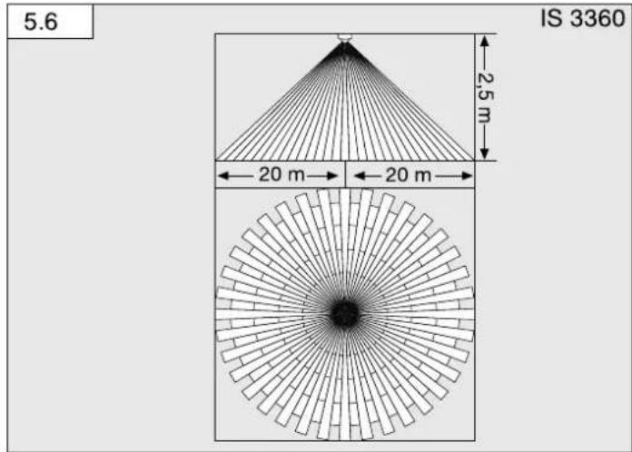
Detection zone/reach
IS 3360 (Fig. 5.6)
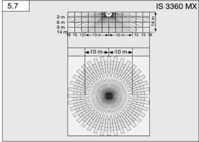
IS 3360 MX (Fig. 5.7)
| Mounting height Reach (tangential) | |
| 14 m 10 m | |
| 9 m 14 m | |
| 8 m 16 m | |
| 2.8 m | 18 m |
IS 345 (Fig. 5.8)
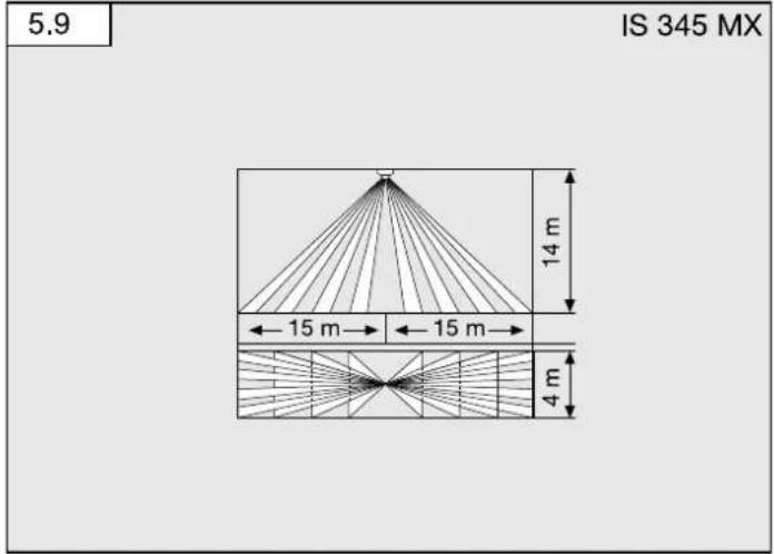
IS 345 MX (Fig. 5.9)
| Mounting height Reach (tangential) | |
| 14 m 30 m × 4 | |
| 10 m 25 m × 4 | |
| 8 m 20 m × 4 | |
| 6 m 15 m × 4 | |
| 4 m 10 m × 4 | |
IS 3180 (Fig. 5.10)
| Mounting height | 20 m lens 8 m lens | |||||
| Setting level | tangential radial | Setting level | tangential | radial | ||
| 1.5 m 8.5 m | 2.5 m 4.3 m 2.0 m | |||||
| -6 m 2.5 m | -5 m 2.5 m | |||||
| -7 m 3.0 m | -6 m 3.0 m | |||||
| -8 m 3.0 m | -7 m 3.0 m | |||||
| 20 | 12 m | 4.5 m 8.9 m | 3.5 m | |||
| 2.0 m 8.5 m | 2.6 m 4.4 m 3.0 m | |||||
| -6 m 3.0 m | -5 m 3.0 m | |||||
| -7 m 3.5 m | -6 m 3.0 m | |||||
| -10 m | 4.0 m - 8 | m 3.0 m | ||||
| 20 | 20 m | 4.5 m 8.8 m | 3.5 m | |||
| 2.5 m 8.6 m | 3.0 m 4.5 m 3.0 m | |||||
| -8 m 4.0 m | -7 m 3.5 m | |||||
| -10 m | 5.0 m - 8 | m 3.5 m | ||||
| -13 m | 5.0 m - 9 | m 4.0 m | ||||
| 20 | 20 m | 4.0 m 8.10 m | 3.5 m | |||
| 3.0 m 8.6 m | 4.0 m 4.5 m 3.0 m | |||||
| -9 m 4.5 m | -6 m 3.0 m | |||||
| -12 m | 5.0 m - 8 | m 4.0 m | ||||
| -17 m | 4.0 m - 10 | m 4.5 m | ||||
| 20 | 20 m | 4.0 m 8.13 m | 5.5 m | |||
Note:
The factory setting is 20 m
- Fit sensor and load module together and screw into place.
- Switch ON power supply.
- Set functions. ( "6. Function")
- Fit designer trim.
6. Function / operation
Factory settings
Twilight level: 1000 lux
Time setting: 5 s
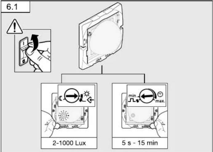
Twilight setting (Fig. 6.1)
The chosen sensor response threshold is infinitely adjustable from approx. 2-1000 lux. Control dial (C) means twilight mode at approx. 2 lux.
Control dial means daylight operation / independent of ambient light level.
Teach mode
The control must be set to at the level of light at which you want the sensor to respond to movement from now on. The level of ambient brightness measured in this way will be saved after 10 seconds. The load is deactivated during this period.
Dazzle guard
This product is equipped with an integrated dazzle guard. If blinded by extraneous light, this puts the sensor into a brightness-related evaluation mode for 60 seconds.
(→ "12. Troubleshooting")
Presence detector switch-off logic
The load connected is switched OFF once the selected light level is exceeded.
Time setting (Fig. 6.1)
The time you want the connected lamp to stay ON for is infinitely adjustable from approx. 5 seconds of a maximum of 15 minutes. Any movement detected before this time elapses will restart the timer.
Pulse function ∩
The pulse function activates the output for 2 seconds (e.g. for staircase lighting time switches). The sensor will then be in a dead time for 8 seconds.
Note:
If the pulse function is selected via the controller, time cannot be set via remote control.
Manual override function (Fig. 4.1)
If a mains switch is installed in the mains supply lead, the following functions are available in addition to simply switching ON and OFF:
Important: The switch should be actuated in rapid succession (in the 0.5 - 1 s range).
Sensor mode
1) Switch light ON (when light is OFF); switch ON and OFF once. Sensor stays ON for the period selected.
2) Switch light OFF (when light is ON): switch ON and OFF once. Sensor goes out or switches to sensor mode.
Manual override
1) Activate manual override:
Switch ON and OFF twice. The sensor is set to stay ON for 4 hours (red LED lights up behind the lens). Then it returns automatically to sensor mode (red LED OFF).
2) Deactivate manual override:
Switch ON and OFF once. Sensor goes out or switches to sensor mode.
LED function
- Normal mode: LED stays OFF
- Test mode: LED lights up on detecting movement
- Remote control: LED flashes approx. 10 times per second
- Permanently ON/OFF: LED lit
7. Accessories (optional)
User remote control RC5 EAN 4007841 592806
Additional functions. RC5
-Light ON/OFF 4 h
-User reset
-100 h burn in, 4 h light ON press for ≥ 5 s
Service remote control RC8 EAN 4007841 559410
Additional functions. RC8
-Time setting, CH1
-Test / normal mode
-Twilight setting
-Night-time operation
-Daylight operation
-Teach-IN
-Reset
Smart Remote EAN 4007841 009151
-Control via smartphone or tablet
-Replaces remote controls RC5 and RC8
-Load appropriate app and connect via Bluetooth
-Identify the sensors and read parameters
Additional functions, Smart Remote
-Time setting: 5 s - 60 min
Twilight setting: 2-1000 lux
Initial state; behaviour after applying the light ON/OFF supply voltage
-Burn in
-Sensor
Detailed descriptions are provided in the operating instructions for the particular remote control.
8. Operation / maintenance
The infrared sensor can be used for switching light ON and OFF automatically. The unit is not suitable for burglar alarm systems as it is not tamperproof in the manner prescribed for such systems. Weather conditions may affect the way the motion detector works. Strong gusts of wind, snow, rain or hail may cause the light to come ON when it is not wanted because the sensor is unable to distinguish between sudden changes of temperature and sources of heat. The detector lens may be cleaned with a damp cloth if it gets dirty (do not use cleaning agents).
9. Disposal
Electrical and electronic equipment, accessories and packaging must be recycled in an environmentally compatible manner.

Do not dispose of electrical and electronic equipment as domestic waste.
EU countries only:
Under the current European Directive on Waste Electrical and Electronic Equipment and its implementation in national law, electrical and electronic equipment no longer suitable for use must be collected separately and recycled in an environmentally compatible manner.
10. Manufacturer's Warranty
As purchaser, you are entitled to your statutory rights against the vendor. If these rights exist in your country, they are neither curtailed nor restricted by our Warranty Declaration. We guarantee that your STEINEL Professional sensor product will remain in perfect condition and proper working order for a period of 5 years. We guarantee that this product is free from material-, manufacturing- and design flaws. In addition, we guarantee that all electronic components and cables function in the proper manner and that all materials used and their surfaces are without defects.
Making Claims
If you wish to make a claim, please send your product complete and carriage paid with the original receipt of purchase, which must show the date of purchase and product designation, either to your retailer or contact us at STEINEL (UK) Limited,
25 Manasty Road, Axis Park, Orton Southgate, Peterborough, PE2 6UP, for a returns number. For this reason, we recommend that you keep your receipt of purchase in a safe place until the warranty period expires. STEINEL shall assume no liability for the costs or risks involved in returning a product.
For information on making claims under the terms of the warranty, please go to www.steinel-professional.de/garantie
If you have a warranty claim or would like to ask any question regarding your product, you are welcome to call us at any time on our Service Hotline 01733 366700.

- Technical specifications
| IS 3180 | IS 3360 / IS 3360 MX | IS 345 IS 345 MX | ||
| Dimensions(L × W × H) | Surface-mounted installation, round 126 × 65 mmSurface-mounted installation, square 95 × 95 × 65 mmConcealed installation, round 124 × 78 mmConcealed installation, square 94 × 94 × 78 mm | |||
| Output Incandescent / halogen lamp load 2000 WFluorescent lamps, electronic ballast 1500 WFluorescent lamps, uncorrected 1000 VAFluorescent lamps, series-corrected 400 VAFluorescent lamps, parallel-corrected 400 VALow-voltage halogen lamps 2000 VALED < 2 W 100 W2 W < LED < 8 W 300 WLED > 8 W 600 WCapacitive load 176 μF | ||||
| Mains powersupply | 220-240 V, 50 / 60 Hz max. 2.5 mm? | |||
| Angle ofcoverage | 180° with 90°angle of perture | 360° with 180°angle of aperture | 180° with 45°angle of perture | 180° with 45°angle of perture |
| Reaches Basic | setting 1:max. 8-20 m tangential; temperature stabilisedBasic setting 2:max. 4-8 m: temperature stabilised + precision adjustment by repositioning the lens and using shrouds | IS 3360max. 20 m tangential; temperature stabilisedIS 3360 MXmax. 18 m; temperature stabilised + precision adjustment using shrouds | max. 23 × 6 m (tangential), max. 12 × 6 m (radial); temperature stabilised + precision adjustment using shrouds | max. 30 × 4 m (tangential) mounted at a height of 14 m; temperature stabilised + precision adjustment using shrouds |
| Detection levels 7 | 11 5 5 | |||
| Switching zones | 448 | 1416 | 280 | 120 |
| Time setting | 5 s - 15 min + pulse mode (approx. 2 s) | |||
| Twilight setting | 2-1000 lux + teach mode | |||
| Manual override(permanent light) | selectable (4 h) | |||
| IP rating Surface-mounted: IP 54 Concealed: IP20 | ||||
| Temperaturezone | -20°C to +50°C | |||
- Troubleshooting
| Malfunction Cause Remedy | ||
| No power at the sensor | ■ Fuse faulty, not switched ON, break in wiring■ Short circuit | ■ New fuse, tum ON power switch, check wiring with voltage tester■ Check connections |
| Sensor will not switch ON | ■ Twilight setting set to night-time mode during daytime operation■ Bulb faulty■ Mains power switch OFF■ Fuse faulty■ Detection zone not properly targeted | ■ Adjust setting■ Change bulb■ Switch ON■ Fit new fuse, check connection if necessary■ Readjust |
| Sensor will not switch OFF | ■ Continuous movement in the detection zone■ Light being operated is located in detection zone and keeps switching ON as a result of temperature change■ Light being operated is in manual override mode (LED ON) | ■ Check zone, adjust or fit shrouds if necessary■ Change detection zone or fit shrouds■ Deactivate manual override |
| Sensor keeps switching ON/OFF | ■ Light being operated is located in the detection zone■ Animals moving in the detection zone | ■ Change zone or fit shrouds, increase distance■ Change detection zone or fit shrouds |
| Sensor reach change | ■ Change in ambient temperatures | ■ Use shrouds to define detection zone precisely |
Malfunction Cause Remedy
| Sensor responds when it should not | Wind moving trees and bushes in the detection zoneCars in the street are being detectedSunlight is shining on the lensSudden temperature changes due to weather (wind, rain, snow) or air expelled from fans, open windowsDazzle guard activeSensor near Wi-Fi or other wireless communication sources | Change detection zoneChange detection zoneMount sensor in a sheltered place or change detection zoneChange detection zone, mount in a different placeSwitch OFF manually at pushbutton/switchNo movement detected within the selected stay-ON time + 60 sec (dazzle guard)Install at least 2 m away from the wireless communication source |
| LED flashes once every 15 s | Load connected is too high | Reduce load or use contactor |