CM 4 - Measuring equipment BENNING - Free user manual and instructions
Find the device manual for free CM 4 BENNING in PDF.
User questions about CM 4 BENNING
0 question about this device. Answer the ones you know or ask your own.
Ask a new question about this device
Download the instructions for your Measuring equipment in PDF format for free! Find your manual CM 4 - BENNING and take your electronic device back in hand. On this page are published all the documents necessary for the use of your device. CM 4 by BENNING.
USER MANUAL CM 4 BENNING
Fig. 6: Frequency measurement
Fig. 7: Battery replacement
Fig. 7: Remplacement de la pile
Fig. 7: Cambio de bateria
Obr. 7: Vymena bateri
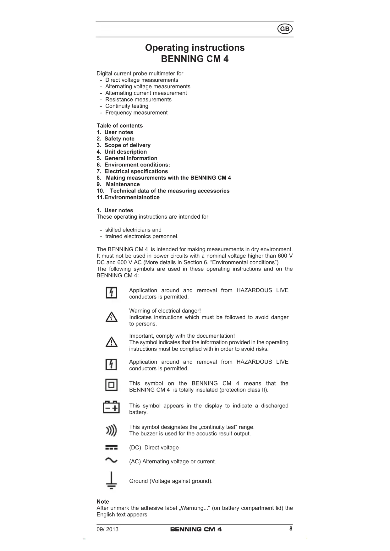
Operating instructions BENNING CM 4
Digital current probe multimeter for
- Direct voltage measurements
- Alternating voltage measurements
- Alternating current measurement
- Resistance measurements
- Continuity testing
- Frequency measurement
Table of contents
- User notes
- Safety note
- Scope of delivery
- Unit description
- General information
- Environment conditions:
- Electrical specifications
- Making measurements with the BENNING CM 4
- Maintenance
- Technical data of the measuring accessories
11.Environmentalnotice
1. User notes
These operating instructions are intended for
- skilled electricians and
- trained electronics personnel.
The BENNING CM 4 is intended for making measurements in dry environment. It must not be used in power circuits with a nominal voltage higher than 600V DC and 600V AC (More details in Section 6. "Environmental conditions") The following symbols are used in these operating instructions and on the BENNING CM 4:

Application around and removal from HAZARDOUS LIVE conductors is permitted.

Warning of electrical danger!
Indicates instructions which must be followed to avoid danger to persons.

Important, comply with the documentation! The symbol indicates that the information provided in the operating instructions must be complied with in order to avoid risks.

Application around and removal from HAZARDOUS LIVE conductors is permitted.

This symbol on the BENNING CM 4 means that the BENNING CM 4 is totally insulated (protection class II).

This symbol appears in the display to indicate a discharged battery.

This symbol designates the "continuity test" range. The buzzer is used for the acoustic result output.

(DC) Direct voltage

(AC) Alternating voltage or current.

Ground (Voltage against ground).
Note
After unmark the adhesive label „Warning...“ (on battery compartment lid) the English text appears.
2. Safety note
The instrument is built and tested in accordance with DIN VDE 0411 part 1/ EN 61010-1
and has left the factory in perfectly safe technical state.
To maintain this state and ensure safe operation of the appliance tester, the user must observe the notes and warnings given in these instructions at all times.

The BENNING CM 4 may be used only in power circuits within the overvoltage category III with a conductor for 600V max. to earth.
Only use suitable measuring leads for this. With measurements within measurement category III, the projecting conductive part of a contact tip of the measuring leads must not be longer than 4mm
Prior to carrying out measurements within measurement category III, the push-on caps provided with the set and marked with CAT III and CAT IV must be pushed onto the contact tips. The purpose of this measure is user protection.
Remember that work on electrical components of all kinds is dangerous. Even low voltages of 30V AC and 60V DC may be dangerous to human life.

Before starting the appliance tester up, always check it as well as all cables and wires for signs of damage.
Should it appear that safe operation of the appliance tester is no longer possible, it should be shut down immediately and secured to prevent it being switched on accidentally.
It may be assumed that safe operation is no longer possible:
- if the instrument or the measuring cables show visible signs of damage, or
- if the appliance tester no longer functions, or
- after long periods of storage under unfavourable conditions, or
- after being subjected to rough transport.

In order to avoid danger,
- do not touch the bare prod tips of the measuring cables measuring probes,
insert the measurement lines in the appropriately designated measuring sockets on the multimeter
3. Scope of delivery
The scope of delivery for the BENNING CM 4 comprises:
3.1 One BENNING CM 4,
3.2 One safety measuring cable, red (L = 1.4m)
3.3 One safety measuring cable, black (L = 1.4m)
3.4 One compact protective pouch,
3.5 Two 1.5-V-mignon-batteries fitted in the unit as original equipment,
3.6 One operating instructions manual
Parts subject to wear:
The BENNING CM 4 is supplied by two 1.5V mignon batteries (IEC LR 06). The above-mentioned safety measuring cables (tested accessories) correspond to CAT III 1000 V and are approved for a current of 10A .
4. Description of appliance tester
See figure 1: Appliance front face
The display and operator control elements specified in Fig. 1 are designated as follows:
Digital display, for the measurement value, bar graph display, overranging display,
Polarity indication,
3 Battery status indication, appears when the battery is discharged,
4 Button (yellow), display lighting,
HOLD button, storage of the indicated measured value,
MIN/MAX button, storage of the highest and lowest measured values ,
Button PEAK, peak value storage,
3 Rotary switch, for selecting the measurement function,
9 Jack (positive 1), for V,
COM jack, common socket for voltage, resistance, measurement, and continuity testing,
Opening lever, for opening and closing the current probe.
Bulge of current probe, protects against contact with conductor.
13 Measuring pliers, for clamping on the single wire current-carrying conductor.
) This is what the automatic polarity indication for DC voltage refers to
5. General information
5.1 General details on the current probe multimeter
5.1.1 The digital display is a 3% - digit liquid crystal display with 14 mm high numerals, complete with decimal point. The largest numerical value which can be displayed is 4000.
5.1.2 The polarity indication 2 is automatic. Only one polarity with respect to the socket marked " - " is indicated.
5.1.3 The overranging is indicated by "0L" or "- 0L" and, in part, an acoustic warning.
Warning, no indication and prior warning in the event of an overload condition!
5.1.4 Button (yellow) ④ switches on the display illumination. Shutdown is effected by a renewed press of the button or automatically after 60 seconds.
5.1.5 Measured value storage "HOLD": Press the button "HOLD" 5 to store the measured result. At the same time, the display shows the symbol "HOLD". A renewed press of the button switches back into measuring mode.
5.1.6 The MIN/ MAX button function inputs and stores automatically the highest and lowest measured value. The following values are indicated by button operation:
"MAX" indicates the stored maximum value, and "MIN" indicates the lowest value. The continuous detection of the MAX-/ MIN value can be stopped or started by pressing the button "HOLD". Pressing the button "MIN/MAX" for an extended period of time (2 seconds) switches back into normal mode.
5.1.7 The button PEAK (peak value storage) detects and stores the positive and negative peak / crest value in the function V AC and A AC. At the start of the measurement, press the button PEAK for approx. 3 seconds in order to increase measurement precision and to fine-adjust the BENNING CM 4. Pressing the button indicates the "PMAX" or "PMIN" values in the display. An extended operation (2 seconds) of the button PEAK switches back into a standard mode.
5.1.8 The measuring rate of the BENNING CM 4 amounts nominally to 1.5 measurements per second for the digital display.
5.1.9 The BENNING CM 4 is switched on and off with the rotary switch ⑧ . Shutdown position "OFF".
5.1.10 The BENNING CM 4 switches off automatically after approx. 30 minutes (APO, Auto-Power-Off). It switches back on again if a button or the rotary switch is operated. A buzzer tone signals automatic switchoff of the appliance. The automatic switchoff can be deactivated by pressing a button (except the button "HOLD") and simultaneously switching on the BENNING CM 4 from switch position "OFF".
5.1.11 Temperature coefficient of the measured value: 0.2 × (stated measuring precision)/ ^ C < 18^ C or >28^ C , related to the value for the reference temperature of 23^ C .
5.1.12 The BENNING CM 4 is supplied by two 1.5 V mignon batteries (IEC LR 06).
5.1.13 If the battery voltage drops below the specified operating voltage of the BENNING CM 4, then a battery symbol appears in the display.
5.1.14 The life span of a battery amounts to approx. 600 hours (alkali battery).
5.1.15 Appliance dimensions:
(L × W × H) = 220 × 83 × 45 ~mm
Appliance weight: 324 g
5.1.16 The safety measuring cables supplied are expressly suited for the rated voltage and the rated current of the BENNING CM 4.
5.1.18 Largest opening of pliers: 37mm
5.1.17 Largest cable diameter: 34 mm
6. Environment conditions:
- The BENNING CM 4 is intended for making measurements in dry environment.
- Maximum barometric elevation for making measurements: 2000 m ,
- Overvoltage category/ Siting category: IEC 60664-1/ IEC 61010-1 600 V category III,
-
Contamination class: 2,
-
Protection Class: IP 30 (DIN VDE 0470-1 IEC/ EN 60529)
IP 30 means: Protection against access to dangerous parts and protection against solid impurities of a diameter >2.5mm (3 - first index). No protection against water, (0 - second index).
- Operating temperature and relative humidity:
For operating temperature from 0^ to 30^ : relative humidity less than 80%
For operating temperatures from 31^ to 40^ : relative humidity less than 75%
For operating temperature from 41^ to 50^ : relative humidity less than 45%
- Storage temperature: The BENNING CM 4 can be stored at any temperature in the range from -20 °C to +60 °C (relative humidity from 0 to 80%). The battery should be taken out of the instrument for storage.
7. Electrical specifications
Note: The measuring precision is specified as the sum of
-
a relative fraction of the measured value and
-
a number of digits (counting steps of the least significant digit).
This specified measuring precision is valid for temperatures in the range from 18^ to 28^ and relative humidity less than 80% .
7.1 Direct voltage ranges
The input resistance amounts to 1 MΩ
| Measuring range | Resolution | Meas. precision | Overload protection |
| 400 V 0.1 V | ± (0.7 % of the measuring value + 2 digits) | 600 \(V_{\text{eff}}\) | |
| 600 V 1 V | ± (0.7 % of the measuring value + 2 digits) | 600 \(V_{\text{eff}}\) |
7.2 Alternating voltage ranges
The input resistance amounts to 1M in parallel 100~pF
| Measuring range | Resolution | Meas. precision *1 within the frequency range 50 Hz - 500 Hz | Overload protection | |
| 400 V 0,1 V | ± (1 % of the measuring value + 5 digits) | 600 V | eff | |
| 600 V 1 V | ± (1 % of the measuring value + 5 digits) | 600 V | eff | |
*1 The measured value is obtained by mean value rectification and displayed as r.m.s. value. Its calibration is matched to a sinus-shaped curve type.
7.3 Alternating current ranges
| Measuring range | Resolution | Meas. precision * \( {}^{ \dagger } \) within the frequency range \( {50}\mathrm{\;{Hz}} - {60}\mathrm{\;{Hz}} \) | Overload protection |
| 60 A | 0,1 A | \( \pm \left( {{1.9}\% \text{of the measuring value + 7 digits}}\right) \) | \( {600}{\mathrm{\;A}}_{\text{eff }} \) |
| 400 A | 0,1 A | \( \pm \left( {{1.9}\% \text{of the measuring value + 5 digits}}\right) \) | \( {600}{\mathrm{\;A}}_{\text{eff }} \) |
| 600 A | 1 A | \( \pm \left( {{1.9}\% \text{of the measuring value + 5 digits}}\right) \) | \( {600}{\mathrm{\;A}}_{\text{eff }} \) |
| within the frequency range \( {61}\mathrm{\;{Hz}} - {400}\mathrm{\;{Hz}} \) | |||
| 400 A | 0,1 A | \( \pm \left( {{2.5}\% \text{of the measuring value + 7 digits}}\right) \) | \( {600}{\mathrm{\;A}}_{\text{eff }} \) |
| 600 A | 1 A | \( \pm \left( {{2.5}\% \text{of the measuring value + 7 digits}}\right) \) | \( {600}{\mathrm{\;A}}_{\text{eff }} \) |
*1 The measured value is obtained by mean value rectification and displayed as r.m.s. value. Its calibration is matched to a sinus-shaped curve type.
The stated precision is specified for conductors that are centrally clamped by the current probe (see Fig. 4 alternating current measurement). For conductors that are not centrally clamped, an additional error of 1% of the display value needs to be taken into account.
7.4 Resistance measuring range and acoustic continuity testing
Overload protection: 600V_eff
| Meas. range | Resolution | Meas. precision | Max. idling voltage |
| 400 Ω | 0,1 Ω | ± (1 % of the measuring value + 3 digits) | 3 V |
The built-in buzzer sounds in the case of a resistance R less than 30
7.5 Frequency ranges
Overload protection: 600A_eff
| Meas. range | Resolution | Meas. precision |
| 400 Hz | 1 Hz | ± (0.1 % of the measuring value + 2 digits) |
| Minimum input frequency: 20 Hz | ||
Minimum sensitivity: 3A_eff
7.6 PEAK HOLD
Measuring ranges: V AC, AAC
Coupling type: AC
In the PEAK-HOLD function (peak value storage) an additional error needs to be taken into account for the specified precision.
- (± 3% + 10 digits)
Measurement values: >600V or 600A_Peak are not specified
- Making measurements with the BENNING CM 4
8.1 Preparations for making measurements
Operate and store the BENNING CM 4 only at the specified storage and operating temperatures conditions. Avoid continuous insulation.
- Checkrated voltage and rated current details specified on the safety measuring lines. The nominal voltage and current ratings of the safety measuring cables included in the scope of delivery correspond to the ratings of the BENNING CM 4.
- Check the insulation of the safety measuring cables. Discard the safety measuring cables immediately if the insulation is damaged.
- Check safety measuring lines for continuity. If the conductor in the safety measuring line is interrupted, the safety measuring line must be quarantined immediately.
Before - at the rotary switch a different function is selected, the safety measuring lines must be disconnected from the measuring point. - Strong sources of interference in the vicinity of the BENNING CM 4 can lead to unstable readings and measuring errors.
8.2 Voltage measuring
Do not exceed the maximum permitted voltage with respect to earth potential! Electrical danger!
The highest voltage which may be applied to the jacks,
-
COM socket
-
jack for V,
of the BENNING CM 4 against ground, amounts to 600V
- Use the rotary switch to select the required function (V AC) or (V DC) on the BENNING CM 4.
- The black safety measuring cable has to be contacted with the COM jack on the BENNING CM 4.
- The red safety measuring cable has to be connected to the jack for V, on the BENNING CM 4.
- Bring the safety measuring lines into contact with the measuring points, read off measured value on the digital display on the BENNING CM 4.
See figure 2: Direct voltage measurement
See figure 3: Alternating voltage measurement
8.3 Alternating current measurement
8.3.1 Preparations for making measurements
Operate and store the BENNING CM 4 only at the specified storage and operating temperatures conditions. Avoid continuous insulation.
Strong sources of interference in the vicinity of the BENNING CM 4 can lead to unstable readings and measuring errors.
Do not apply any voltage to the output contacts of the BENNING CM 4! Any possibly connected safety measuring cables have to be removed.
8.3.2 Alternating current measurement
- Use the rotary switch to select the required function (A AC) on the BENNING CM 4.
- Operate opening lever , clamp single wire live conductor centrally by means of the BENNING CM 4 current probe.
- Read off the digital display unit.
See figure 4: Alternating current measurement
8.4 Resistance measuring and acoustic continuity testing
- Use the rotary switch to select the required function () on the BENNING CM 4.
- The black safety measuring cable has to be contacted with the COM jack on the BENNING CM 4.
The red safety measuring cable has to be connected to the jack for V, , Hz on the BENNING CM 4.
- Bring the safety measuring lines into contact with the measuring points, read off measured value on the digital display on the BENNING CM 4.
- If the conductor resistance between the COM jack and the jack for V, , 30 , the fitted buzzer sounds on the BENNING CM 4.
See figure 5: Resistance measurements
8.5 Frequency measurement via current measuring pliers

Do not apply any voltage to the output contacts of the BENNING CM 4! Any possibly connected safety measuring cables have to be removed.
- Use the rotary switch to select the required function (Hz) on the BENNING CM 4.
- Operate opening lever , clamp single wire live conductor centrally by means of the BENNING CM 4 current probe.
- Read off the digital display unit.
See figure 6: Frequency measurement via current measuring pliers
- Maintenance

Before opening the BENNING CM 4, make quite sure that it is voltage free! Electrical danger!
Work on the opened BENNING CM 4 under voltage may be carried out only by skilled electricians with special precautions for the prevention of accidents.
Make the BENNING CM 4 voltage free as follows before opening the instrument:
- First remove the two safety measuring lines from the object to be measured.
- Then disconnect the two safety measuring cables from the BENNING CM 4.
- Turn the rotary switch to the switch setting "OFF".
9.1 Securing the instrument
Under certain circumstances safe operation of the BENNING CM 4 is no longer ensured, for example in the case of:
Visible damage of the casing.
- Incorrect measurement results.
- Recognisable consequences of prolonged storage under improper conditions.
- Recognisable consequences of extraordinary transportation stress.
In such cases the BENNING CM 4 must be switched off immediately, disconnected from the measuring points and secured to prevent further utilisation.
9.2 Cleaning
Clean the casing externally with a clean dry cloth (exception: special cleaning wipers). Avoid using solvents and/ or scouring agents for cleaning the instrument. It is important to make sure that the battery compartment and battery contacts are not contaminated by leaking electrolyte.
If electrolyte contamination or white deposits are present in the region of the batteries or battery casing, clean them too with a dry cloth.
9.3 Battery change

Before opening the BENNING CM 4, make quite sure that it is voltage free! Electrical danger!
The BENNING CM 4 is fed by two 1.5-V mignon batteries.
A battery change (see Figure 7) is required, if the battery symbol appears.
Proceed as follows to replace the batteries:
- Disconnect the safety measuring cables from the measuring circuit.
- Disconnect the safety measuring cables from the BENNING CM 4.
- Set the rotary switch to the switch setting "OFF".
- Lay the BENNING CM 4 face down and release the slot screws of the battery compartment cover.
- Lift the battery compartment lid (in the housing recess area) from the bottom section.
- Lift the discharged battery from the battery compartment and disconnect the battery supply lines from the battery.
- The new batteries have to be connected to the battery supply lines, and arrange these such that they are not crushed between the housing parts. Then place the batteries into the battery compartment provided for this purpose.
- Place the battery compartment cover onto the bottom part and tighten the screw.
See figure 7: Battery replacement

Make your contribution to environmental protection! Do not dispose of discharged batteries in the household garbage. Instead, take them to a collecting point for discharged batteries and special waste material. Please inform yourself in your community.
9.5 Calibration
To maintain the specified precision of the measurement results, the instrument must be recalibrated at regular intervals by our factory service. We recommend a recalibration interval of one year. Send the appliance to the following address:
10. Technical data of the measuring accessories
- Standard: EN 61010-031,
- Maximum rated voltage to earth (1等) and measuring category:
With push-on caps: 1000 V CAT III, 600 V CAT IV,
Without push-on caps: 1000 V CAT II,
Maximum rated current: 10 A,
- Protective class II (回), continuous double or reinforced insulation,
- Contamination class: 2
Length: 1.4m AWG 18
-Environmentalconditions:
Maximum barometric elevation for making measurements: 2000m
Temperatures: 0^ to +50^ , humidity 50% to 80%
- Only use the test leads if in perfect and clean condition as well as according to this manual, since the protection provided could otherwise be impaired.
- Throw the test leads out if the insulation is damaged or if there is a break in the cable/ plug.
- Do not touch the bare contact tips of the test leads. Only grab the area appropriate for hands!
- Insert the angled terminals in the testing or measuring device.
11.Environmentalnotice

At the end of the product's useful life, please dispose of it at appropriate collection points provided in your country.
(CC) Tension continue

Pn6op MoXHO nCNoB3OBAbT dny npoBeHn y3MepeHn Ha HEn3OInpOBaHHbIX npoBOdax.

Onachoctb nopaxKeHHaJIeKTPnueckm TOKOM!
Yka3bIbaet Ha HNCTpykUIN, KOtOpBie Heo6xOdIMo Co6JIIOdaTb BO n36eKahHe npaKeHnepcoHaHa 3JIeKTPuYeCKM TOKOM.

BHHMaHHe, cIeDyIte yka3aHnM TexHnueckOJ DOKymEHTaUIN! Yka3bIbAet Ha IHCTpyKUIN pyKOBOdCTBa NO 3KcNlYaTauuN, co6JIouDeHne KOToPbIX o8a3aTeIbHO dIra 6e3OnaCHOI 3KcNpyatauN.

JaHHbI CNMBON Ha npnbope yka3bIBaet Ha nonHyo n3OJauIO npnbopa (Knacc 3aunTbI II).

CIMBOJ NOBJIETCA Ha npi6ope npi pa3p8KeHHo 6aTaapee.

CIMBOJ NOBnIeTcHa DncJIeE BpeKIme npO3BOHKn ZenN.

0603nauaet noctoHHe HnpanKeHne nTOK.

0603nauaet nepemehnoe hnapjkeHne nnTOK.

Pnp6op npedHa3nueH nIe IcnoJb3ObaHHB c KaTeOpne 3aunTbI OT nepeHanpJxHeHH III C MaKcMaJIbHbIM HanpJxHeHHem 600 B.
NcnoB3yTe COOTBeTCTByIOUne N3MepeHn npINBOaNT K 3ToMy. Ppi N3MepeHnX B dHa nana3OHa XaTEROpn N3MepeHn III BbCTynaHO-ua, TOKONpOBOJaA qAcTb KOHTaKTHoro OcTpna Ha 3aunTHbIX N3MePnteJIbHbIX pPOBoaX DoJxHa HMeTb DInHy He 6OJee 4 MM.
Ipeed n3MepeHem B dana3OHe KaterOpn n3MepeHnra III Heo6xOJIMO HacaNTb Ha KOHTaKTHbIe OCTpna HacaNbIe KOJINaKn, HaxoJaUneCeB KOMPJIeKT N IMeHOJNe O6O3HaueHnCAT III nCAT IV. 3To Heo6xOJIMO dnnr 3aunTbI onepatopa. IIO6a pa6ota c 3JeKTPnueCTBOM ABJnETrc NOteHuaJIbHO onachOn! DaKe HanpJXeHn BEINuHOn 30 B nepemeHHoro TOKa nn 60 B NoctoHHoro Toka MOrY 6bITb ONaChbl nJKN3HN.

Ipeed nCnoB3OBAHnem np6opa y6eInTecb B OTCyTcTBn npn3HaKOB NOBpeXdHnKopnyca N N3Mepntelhblix npoBOdoB.
Ecnn 6e3oNaChnA 3KcNpyataun npmbopa HeB03MOxHa, Heo6XoIMo BbIKIOuHTb np6op n npHraTb Mepbl K ppeOToBpaueHNO erO cnyaHoro NcNoIb3OBAHn.
Be30nachna 3Kcnpnyataun np6opa Heo3moxHa,ecn:
- Na Koprnyce npnbopa nnn Ha n3MepnTeNbHbIX npoBoaX mMeIoTc BnDmBle NOBpejKeHHA
- npnbop He yhkuoHpyeT
- npi6op DoIroe Bpemx XpaHIncB He6laorponpnaTHbIX ycNoBnax
- npi6op noiBeprc TpaHcnpTupOBke B He6laornpraTHbIX ycNoBnax

Bo n36exaHne nopaxeHn 3NeKtpnueckm TOKOM He npkacaTeCb K Xany n3MePnteBbIX npoBOIOB. KoppeKTHO noDKIouaTe np6Op K n3MepreMoI cenN.
3.ObbemnoCTaBKN
B o6bem nocTabkTOKoH3MepeNTeJIbHbIX KneIeBENNING CM 4 BxoOHT:
3.1 Pnp6op BENNING CM 4-1 uT
3.2 KpaCHbI n3MePnteHbI npOBd (dINHa:1,4M)-1 uT.
3.3 Uepnbl n3meptenbbl npoBOd (dlnha:1,4M)-1uT.
3.4 3aunTHa cymka-1 wT.
3.5 BaTapeA TnA AA 1,5 B-2 wt.
3.6PykoBOcTBO no 3KcNpyataun -1 wT.
KomnoentbI, noJnEkaune 3aMeHe no Mepe n3HocA:
- 1,5 B 6aTapeu Tnna AA (IEC LR 06)
- 13MepntbHbIe npOba (kateropn 3aunTbI OT npehanpJxHeN I1000 B, donyctmbl TK do 10 A)
4. Onncanhe npnbopa.
Cm.pnc.1. BnD cnepeeni.
Oprahbly npablenia nHdkaun
1 CnΦpOBo JxNdkOKpncTaNIIueckn DnCnneJ.
2 INdkaTop noJpHocTn
3 HndnkaTOp coCToHnna 6atapei (noBnAeTc npn pa3pJKeHHo 6atapee)
4 Khonka noDCBETKn Dncnnner
5 Khonka HOLD ydepkaHH nokaahn dncnner
6 Khonka MIN/MAX COXpaHeHnMIMHMaJIbHOr/MakcMaJIbHOr 3HaHeHn
7 Khonka PEAK coxpaHnI NIKOBOrO 3HaHeHnI
8 IpeekJIOUaTeIb poJa pa6oT
9 N3MepntenbHoe rHe3do (noIOXnTeBHyI noIOc npn onpeJeHHn noJIaPHoCTn HapJxKeHHNoCTOaHHOro ToKa) IJIa N3MepeHHaHpJxKeHHaCnpoTubNeHHN
10 COM-rHe3do (o6uee u3MepeTJIbHoe rHe3do dIa u3MepeHnHa npJxKeHHN, cOpOTNBHeHn I npO3BOHKn)
KlaBnwa packpbTna ry6ok
12 BbIcTyn Jnla 3aunTbI OT COnpNKoCHOBHeNc TOKOBeUyIm IpOBODOM
3 NImepntbHbIe ry6kn IJnO6Xbata TOKOBedyero npoBOda
5.ObuaHnΦopMaun
5.1 O6uIe TexHnueckne XapaKTepeNCTNK TOKON3MePntbHbIX KJIeUe
5.1.1 Pa3pIaHocTb cIePbOro DnCnpe 1:3%, BbICoTa Cnpp: 14 MM, DeCraTtuaH aTOka, MaKcImaJIbHOe INHdUncIpyeMoE 3HaueHne: 4000
5.1.2 ABTomatnuecka INDnkaunnoJnIpaHocTn 2
5.1.3 BbIXoJ 3a npedeJIb dIana3OHa nHdNcIpyeTcraMBOJOM «OL» Ha IINCIInee n AKKyCTnueCKIM CnIHAlON.
BnHMaHHe, npn nepepy3Ke npnbopa npeBaPntbHoro cnHaHa ne nodaetc!
5.1.4 XeTTaH KONKa 4 BKIOUaET NOcCBEtKy DnCnner. BbIKIOueHne NOCBETKN OCyIeCTBnEeTCR NOBTOPbIM HaxaTHeM DaHHoN KHONKn, NnABOTMATueeCKn NO nCTeueHm 60 c.
5.1.5 Khonka HOLD (coxpaheHnepe3yNbTaTOB n3MepeHn)
Дя coхpaheHЯ (ydepkaHЯ) pe3ynbTaTaN3MepeHna HnncNee HaJXMITE KhoNKy HOLD 5, npn 3TOM Ha DnCnIe NOBNTc HnDKaTOP HOLD. NOBTOpHoe HaxKaTne KhoKn BO3BpaUaet npn6Op B HopMaJIbHbI peKIM N3MepeHIn.
5.1.6 KhoKa MIN/MAX ⑥ (aBtOMaTnueeCKoe coXpaHeHne MaKcMaJIbHOrO/ MInHMaJIbHOro n3MepeHHOrO 3HaYeHn)
HakatneM KHONKNo ObecneuBaetc OTo6paKeHne Ha DCnnee MaKcMaJIbHOrO MAX, INN MINHMaJIbHOrO MIN 3HaueHnI3MepeReMoB BeINHbI. HenpepbIBHOe OTCLeXKBaHHe MaKcMaJIbHOrO/MNHMaJIbHOrO 3HaueHnIOxMOxHO OCTaHabINBaTb/3anyCKaTb HaxaTneM KHONKn HOLD 5.ДЯ Bo3Bpata B HopMaJIbHbI peKIM I3MepeHnRAxKMnTe n ydepKJBaiTe KhoNky MIN/MAX B TeueHne 2 c.
5.1.7 Khonka PEAK (coxpaHHeHne NIKOBOrO 3HaueHnA)
KhONka BKNHouaET pEXM ABtOMaTueCKORo COxpaHeHr NIOXHTeB-HORO INIOTnpuateNBHO rIKOBORO 3NaueHnepemEHORo TOKa ININ HAnpJKeHn. Pepe nauanom n3MepeHn hAXMnte u ydepXnBaTe KhONky PEAK 7 B TeueHne 3 c dnn noBbIeHn ToUHOCTu n3MepeHn n CamohactpoKn np6opa. HaxaTne KhoNkn nonepemehno BBIOaT Ha DnCIne MAKcMaJIbHoe 广 P M A X IIN MNHMmaJIbHoe 广 P M I N 3HaueHn. IIN BO3Bpata B HopMaJIbHbI peKmN n3MepeHn hAXMnte n YdepXnBaTe KhONky PEAK 7 B TeueHne 2 c.
5.1.8 HomnHaIbHoe KOJIuYeCTBO I3MepeHn B CeKyHny coCTaBnaTe 1,5 n3M/C dIra uDpOBO rO dinPJIe.
5.1.9 Kneu BENNING CM 4 BkHouaOTc n BbIKHouaOTc NOBOPOTm nepeKluoyateTn 8. Iy BbIKHoueHn nepeKluoyaTeNb NOMEauOT B noLoxHeN E OFF [BbIKHoueHo].
5.1.10 Kneu BENNING CM 4 aBtOMaTueeckn BbIKIOUaOTcra, ecnB TeueHne 30 mHyr ero orpaHbI ynpabHeHne He nCNoIb3ObaIncb. NobTopHOe BkIOUeHne np6op a OcyseCTBJIeTcra HaxaTneM IIObo KNOpKn nnIOBOPOTmpeKIOUaTeJI 8. Pepe d ABtOMaTueeCKm OTKIOUeHem np6op BbIaET KopoTKn 3ByKOBoi CInHaJ. JIg 6IOKpOBKn FyHKnn ABtOMaTueeCKoro OTKIOUeHnne Heo6XoIMo HaxaTb Ha IIO6yIO KHOKNy (KpOME KHOKNI HOLD) uYepxNBAe ee NOBepHyt bpeKIOUaTeJI 8 n3 NOnOKeHnR «OFF» B Tpe6yEmoe NOnOKeHne.
5.1.11ДононтельнаяnorpeшнocьпиИЗмeHeHnTeMnepaTpyblOKpykaIousei cpeblHa 1^ coCTabJIeT0,2OT npeJena donyckaemoi no-rpeuhoctn (npBbIXOe n3 dInana3oHa 23± 5^)
5.1.12 Kneu BENNING CM 4 noctablanotc B komnke Tc Dbym 1.5 B 6aTapeym Tuna AA (IEC LR06).
5.1.13 Pn pa3pae 6atape Hnke donyctmoro ypoBna Ha dinCnnee np6opa noaBnreTcncBMoI 6atapei.
5.1.14 Cpok cnjx6bl 6aTapeu coCTabnreT npimepno 600 u (ueNoHna 6atape)
5.1.15 Ra6apuTHbIe pa3Mepe: (日 x 山 x B) = 220 × 83 × 45 MM Bec np6opa: 324 r
5.1.16 I3MepntelbHbIe npoBoda npiroDhbI dJIg n3MepeHnRA TOKOB HaprrJxHnB pa6ooyem dnaana3OHe np6opa.
5.1.17 MakcmaIbHoe paKpbItne ry6ok:37 MM
5.1.18 MaKcMaJIbHbI dIaMaTeP Ka6eJIa: 34 MM
6.YcnoBnOkpykaHooe Cpebl
28°C IN OTHOCHTeJIbHOB BJIaXHOCTm MeHee 80%.
7.1 N3mepenne noctoHHoro Hanpexnna
BxOJHOe cOpOTnBHeHne: 1 MOm.
| Преел Раразшени Погreachungь 3ашита Вхда | |||
| 400 B 0,1 B ± (0,007*X + 2*k) 600 B | cp. KB. | ||
| 600 B 1 B | ± (0,007*X + 2*k) | 600 B cp. KB. | |
k=edHnHaMnaDwero pa3pa
7.2 N3mepeHne nepemehHoro HanpJxehn
BxOdHoe cOpOTnBHeHne: 1 MOm (10 nΦ).
| Прееду Радецени | Погашност'1 В длиаце 50 Г-500 Г | Зашто вхда |
| 400 B 0,1 B | ± (0,01*X + 5*k) | 600 B |
| 600 B 1 B | ± (0,01*X + 5*k) | 600 B |
1 I3MepeHHoe 3HaueHne RaBnETCaΦΦeKTHBbIM 3HaueHHeM (cpeHekBa- dpaTnueckoe 3HaueHne). ToHocTb I3MepeHn OnpeJeHa dIaCnHycoN daJIbHO KnBOI.
7.3 ⅢmepeHne nepemehHoro toka
| Преел Раразшени | Погашност*1 В длиаце 50 Г - 60 Г | Зашто вхда |
| 60 A | 0,1 A ± (0,019*X + 7*K) | 600 A cp. KB. |
| 400 A | 0,1 A ± (0,019*X + 5*K) | 600 A cp. KB. |
| 600 A | 1 A ± (0,019*X + 5*K) | 600 A cp. KB. |
| В длиаце 61 Г - 400 Г | ||
| 400 A | 0,1 A ± (0,025*X +7*K) | 600 A cp. KB. |
| 600 A | 1 A ± (0,025*X +7*K) | 600 A cp. KB. |
1 N3MepeHHoe 3NaueHne IaBnIeTcra 3ΦΦeKTHBbIM 3NaueHHeM (NCTNHHOe CpeHekBaDpaTnueCeKoe 3NaueHne, CBa3b NO nepemehHomy TKy). TouHOCTb N3MepeHn ONpeJeHa dIra CNHycondaJIbHO KnBOi.
Yka3aHa TOUHOCTb I3MepeHn, nOlyuHaemar npn pa3MeueHn IpOBOda c TOKOM NOCePeDInHe 3eBa KNeIeJ (cm. pnc. 4 N3MepeHne BeINuHNbI nepeMeHHoro ToKa). PnCmeueHn IpOBOda n3 ceHTpaIbHoro noIOKeHn He-06XoDIMO yUHTbIBaT bONONHTeJIbHyTO NorpeSHocTb B 1%.
7.4 I3mepeHne conpoTnBJIeHn/ npo3BOHka cenN
| Преел Раразшени | Погreachungов 3ацита Вхда | |
| 400 Ω 0,1 Ω | ± (1 % des Messwertes + 3 Digit) | 3 V |
BcTpoeHHbI B np6op 3ymMep Bblaet 3ByKOBo CnHan, ecnn cOnpoTnBJIeHne n3mepreMoU cen Mehee 30 OM.
7.5 3mepeHne yactotbl
MnHmAbhna Yactota Ha BxoJe: 20 T
MnHmMaNbHa YyBCTBtTeNbHOctb Ha BxOe: 3 A cp.KB.
7.6 3anomHHHe NIKOBbIX 3HaYeHn
Pexmbln3mepenH:HaipjKeHne nepemehHoro ToKa (V AC), npemehHbI TOK (A AC)
BpeKIMe 3aONMHaHnI NIKOBbIX 3NaueHn (fynKpIa PEAK-HOLD) Heo6xo- dIMO yuHTbIBaTb DOnOJIHITeNbHyIO nOrpeUHOCTb coCTabNIAOyIO ± (0,03*X + 10^*k)
TouHocTb 3HaueHn IpeBbIaUoJnx 600 B nIe 600 A HeHopMIpObaHa.
8.1 PnOdrTOBkA K npOBeHnIO n3MepeHn
IcnoJIb3yIte IxpaHITe np6Op cornacHO yka3aHm daHHoro pyKOBoDCTBa.
I36eraaTe npoDOnknteBnHO xpaHEnr npb6opa.
- Поверпге Номнаньhoe Hanprженьи TOK ИЗмрптельбх npobodOB. HOMnHaJIbHoe Hanprженьи TOK ИЗмрптельбх npobodOB NOCTaBnE mbyx BmecTe c np6opom BENNING CM 4 COOTBeTCTByIOT napametpam np6opa.
- PpOBepbTe n30JIaIIO uN3MePnteNbHbIX npOBOoB. B cnyae noBpeKdEHHu N30JIaIIN npOBOoB IN x daJIbHeiJee uCnONb3ObaHne 3anpeUeHO.
-Пюоверът ecIOCTHOCt b n3MepnteIbNbIx npOBODB.В сlyuae hapuWeHЯ ceIOCTHOcTN cENn n3MepnteIbHbIX npOBODB IX dAJIbHeiJee IcNoIb3OBAHne 3aIpeUeHO. - PpeD yctahOBKOI nepeKIOUaTeJr poJa pa6oT 8 B HOBOE noLOXeHne HeOxOIMO OTOcEOHNHTb N3MepNTeHbIe IPOBOa OT N3MepREMOI cENI.
- NCTOCHN K CINbHbIX 3JIeKTpOMaTHnTHbIX NOMEX B HENOCpeIcTBeHHo6JIN30CTn OT npB6opa BENNING CM 4 MOryT Bbl3BaTb HeCTa6uNbHOCTb Noka3AHn I OUsbKn n3MepenH.
8.2 3mepeHne HapjkeHH

He npebbwaTe donyctnmoe HanpiaeHne!
Onachoctb nopaxeHn 3JeKtpuyeckm TOKOM!
HanboJbuee HnnpjKeHne KOTopeo MOKHO NOBcTeN K pa3bEaM
-COM 10
V,Ω coCTaBnAeT 600 B.
- BpaueHnem nepeKnUoyateJI 8 yctaHOBtpe pexm n3MepeHnaHapjKeHHnnepeMeHHoro ToKa (V AC) nn HapjKeHHnoCToHHoro ToKa (V DC).
-ПодключпуерньиИЗМерпелови побODКИЗМерпелбHOMY rHe3dY COM10
-Подклочи Красьи ИЗМерпелов Лювд К ИЗМерпелову Гезду V, Ω
-ПОДКЛЮЧITEИЗМЕРITIELБHIEпpoВODApapALNIELbHOиСТОчнky HANPЯKEHINHArpy3Ke.CuNTaTe NONYEHHO3HaueHHeC DnCnPNe1.
cm.pnc.2 13mepeHHe HappkeHHnoCToHHoro Toka
cm.pnc.3 13mepeHne HapjkeHn npemHeHoro Toka
8.3 N3MepeHne nepemehHoro Toka
8.3.1 Poirotobka K npoBeHIO u3MepeHH
IcnoJIb3yIte n xpaHnTe np6bOp cornacho yka3aHm daHHoro pykoBocCTBa. I3-6eRaTe npoDOnKInTeJbHorO xpaHeHn np6bopa.
- IcToUHnKn CnIbHbIX 3JIeKTpOMaHHTbIX NOMEx B HENOCpeDCTBeHHoN 6JIN3OCTn OT npIb6opa BENNING CM 4 MoYr Bbl3BaTb HeCTa6nIbHOCTb Noka3AHn n OUsbKn 3MepenH.

He npnKnaDbBaTb HanpXeHne K rHe3dAm npn6opa!
OTcoeINHHTb N3MepNTeIbHbIe npoBoda!
8.3.2 13mepenne npemehHoro toka
-
BpaueHnem nepeKlnouaTeIy 8 ycTaHOBIne peXm ImMepeHna Cnbl nepemHHoro Toka (A AC).
-
Haxab Ha KnaBnuypackpbltny6ok 0xbaTne KneUamnpoBOd, B KOtOpom Heo6xOdmo npOn3BecTu n3MepeHne Toka.
-
CunTaIe pe3yIbTat n3MepeHnC 3kpaHa dncJIpe 1.
Cm. pnc. 4 I3mepeHne BeJIuHHbI nepeMeHHoro ToKa.
8.4 N3mepehne conpoTHBnEHn/ npo3BOH cenn.
- BpaueHnem npeKIOUaTeJIy 8 yCTaHOBITe pEXIM N3MepeHnA COpOToBJIeHn/ np03BOHa ceni (Ω).
-ПОДКЛЮЧИТЕ Уерній ИЗМерптELьній РобOD K ИЗМерптELьHOMу ГеЗДу COM10