PD501AC - Drill Vonroc - Free user manual and instructions
Find the device manual for free PD501AC Vonroc in PDF.
| Brand | Vonroc |
| Model | PD501AC |
| Product type | Drill press |
| Power supply | 230 V ~ 50 Hz |
| Power consumption | 720 W (S1), 900 W (S6 6 min) |
| Protection class | II (double insulation) |
| No-load speed (speed 1) | 220 - 880 rpm |
| No-load speed (speed 2) | 650 - 2550 rpm |
| Chuck capacity | 1.5 - 13 mm |
| Max drilling depth | 80 mm |
| Distance chuck - base | 85 - 300 mm |
| Base dimensions | 340 x 300 x 40 mm |
| Max drilling diameter (wood) | 40 mm |
| Max drilling diameter (steel) | 13 mm |
| Weight | 7.8 kg |
| Laser | Class 2, 650 nm, < 1 mW, cross lines |
| Work light | Integrated LED |
| Sound pressure level | 79.7 dB(A) (K=3 dB(A)) |
| Sound power level | 90.7 dB(A) (K=3 dB(A)) |
| Main functions | Drilling wood, metal, ceramic, plastic; electronic speed control; depth stop; quick clamp; vise; parallel guide |
| Maintenance and cleaning | Soft damp cloth; no solvents; clean ventilation slots |
| Safety | Protective cover, emergency stop, zero-voltage switch, laser protection |
| Spare parts and repairability | Contact Vonroc customer service; use original parts |
| Warranty | Legal duration from purchase date; exclusion in case of unauthorized repair |
Frequently Asked Questions - PD501AC Vonroc
User questions about PD501AC Vonroc
0 question about this device. Answer the ones you know or ask your own.
Ask a new question about this device
Download the instructions for your Drill in PDF format for free! Find your manual PD501AC - Vonroc and take your electronic device back in hand. On this page are published all the documents necessary for the use of your device. PD501AC by Vonroc.
USER MANUAL PD501AC Vonroc
natural_image
Abstract white geometric shape on black background, resembling a stylized 'V' or chevron (no text or symbols)VONROC®
BUILD YOUR FUTURE
PILLAR DRILL PD501AC

natural_image
Pure electrical circuit lines without any symbolsEN Original Instructions 07


natural_image
Industrial machine labeled 'VONROC' with control panel and mechanical base (no visible text or symbols beyond branding)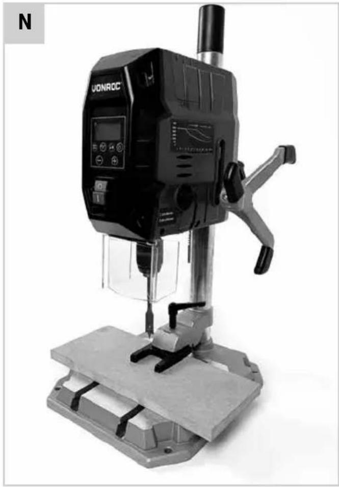
natural_image
Black VONROC drill press machine on a workbench, no visible text or symbols on the device itself.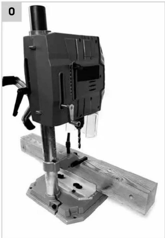
natural_image
Black-and-white photo of a mechanical drill press machine with wooden base and metal components (no visible text or symbols)1.SAFETYINSTRUCTIONS
Read the enclosed safety warnings, the additional safety warnings and the instructions. Failure to follow the safety warnings and the instructions may result in electric shock, fire and/or serious injury. Save the safety warnings and the instructions for future reference.
The following symbols are used in the user manual or on the product:

Read the user manual.

Denotes risk of personal injury, loss of life or damage to the tool in case of non-observance of the instructions in this manual.

Risk of electric shock.

Rotation, left/right.

Wear hearing protection.

Wear a dust protection.

Wear eye protection.

Keep your hair away from moving parts. Tie back long hair, be sure to wear hair protection (hair net or cap). Long hair can easily be caught in moving parts.

Do not wear protective gloves. Gloves may be entangled by the rotating parts or chips leasing to personal injury.

Dress properly. Do not wear loose clothing or jewellery. Keep your clothing away from moving parts. Loose clothes and jewellery can be caught in moving parts. Instead wear fitted clothing and tie buttons on sleeves.

Attention: Laser radiation. Do not stare into the beam Class 2 laser.

Class II machine - Double insulation - You don't need any earthed plug.
CE The product is in accordance with the applicable safety standards in the European directives.
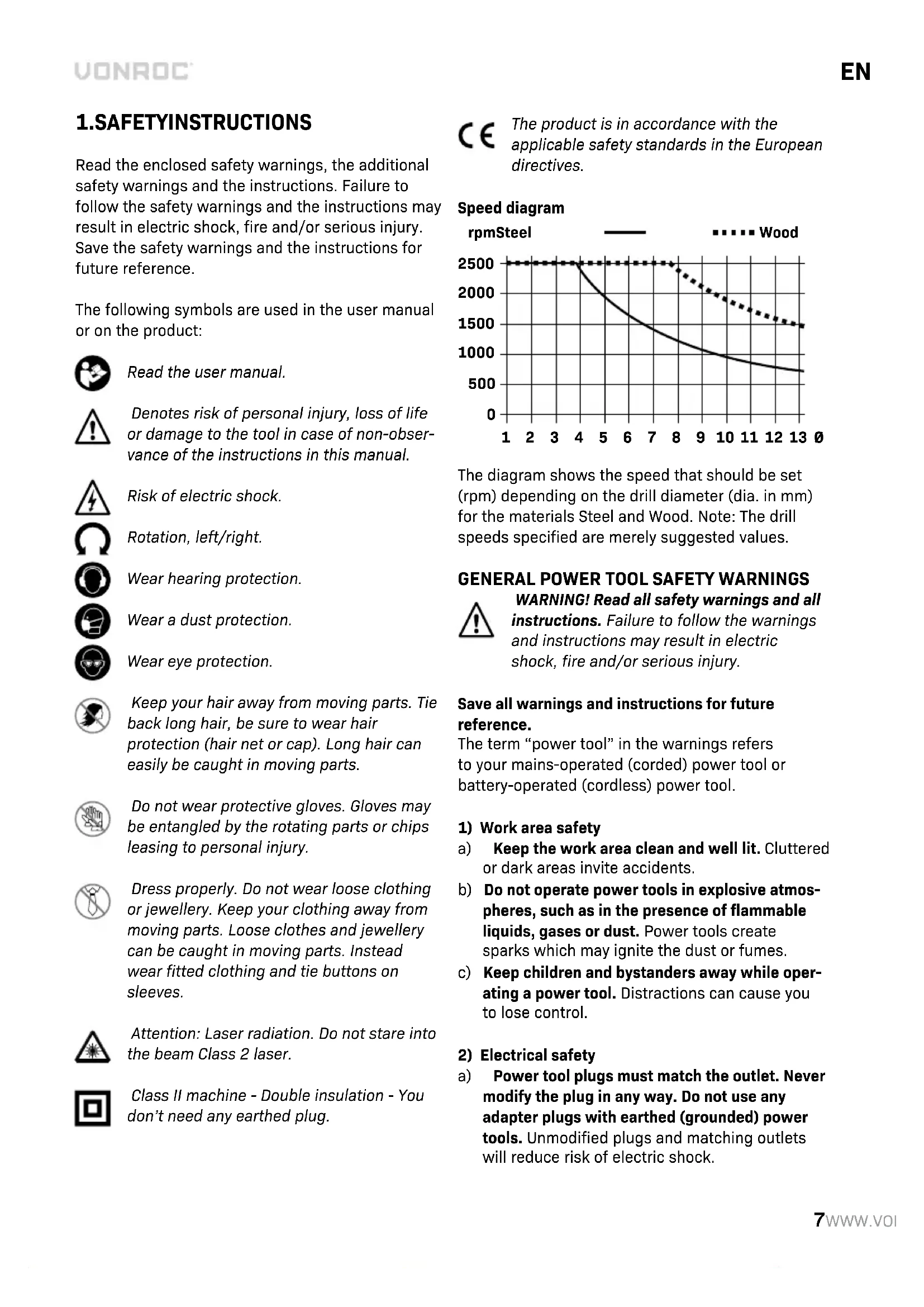
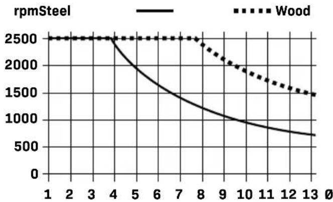
Speed diagram
line
| x | Wood | rpmSteel | |----|-------|----------| | 1 | 2500 | 2500 | | 2 | 2500 | 2500 | | 3 | 2500 | 2500 | | 4 | 2500 | 2500 | | 5 | 2500 | 2000 | | 6 | 2500 | 1700 | | 7 | 2500 | 1500 | | 8 | 2500 | 1300 | | 9 | 2000 | 1100 | | 10 | 1800 | 1000 | | 11 | 1600 | 900 | | 12 | 1500 | 800 | | 13 | 1400 | 700 |The diagram shows the speed that should be set (rpm) depending on the drill diameter (dia. in mm) for the materials Steel and Wood. Note: The drill speeds specified are merely suggested values.
GENERAL POWER TOOL SAFETY WARNINGS
WARNING! Read all safety warnings and all instructions. Failure to follow the warnings and instructions may result in electric shock, fire and/or serious injury.
Save all warnings and instructions for future reference.
The term "power tool" in the warnings refers to your mains-operated (corded) power tool or battery-operated (cordless) power tool.
1) Work area safety
a) Keep the work area clean and well lit. Cluttered or dark areas invite accidents.
b) Do not operate power tools in explosive atmospheres, such as in the presence of flammable liquids, gases or dust. Power tools create sparks which may ignite the dust or fumes.
c) Keep children and bystanders away while operating a power tool. Distractions can cause you to lose control.
2) Electrical safety
a) Power tool plugs must match the outlet. Never modify the plug in any way. Do not use any adapter plugs with earthed (grounded) power tools. Unmodified plugs and matching outlets will reduce risk of electric shock.
b) Avoid body contact with earthed or grounded surfaces, such as pipes, radiators, ranges and refrigerators. There is an increased risk of electric shock if your body is earthed or grounded.
c) Do not expose power tools to rain or wet conditions. Water entering a power tool will increase the risk of electric shock.
d) Do not abuse the cord. Never use the cord for carrying, pulling or unplugging the power tool. Keep cord away from heat, oil, sharp edges or moving parts. Damaged or entangled cords increase the risk of electric shock.
e) When operating a power tool outdoors, use an extension cord suitable for outdoor use. Use of a cord suitable for outdoor use reduces the risk of electric shock.
f) If operating a power tool in a damp location is unavoidable, use a residual current device (RCD) protected supply. Use of an RCD reduces the risk of electric shock.
3) Personal safety
a) Stay alert, watch what you are doing and use common sense when operating a power tool. Do not use a power tool while you are tired or under the influence of drugs, alcohol or medication. A moment of inattention while operating power tools may result in serious personal injury.
b) Use personal protective equipment. Always wear eye protection. Protective equipment such as dust mask, non-skid safety shoes, hard hat, or hearing protection used for appropriate conditions will reduce personal injuries.
c) Prevent unintentional starting. Ensure the switch is in the off-position before connecting to power source and/or battery pack, picking up or carrying the tool. Carrying power tools with your finger on the switch or energising power tools that have the switch on invites accidents.
d) Remove any adjusting key or wrench before turning the power tool on. A wrench or a key left attached to a rotating part of the power tool may result in personal injury.
e) Do not overreach. Keep proper footing and balance at all times. This enables better control of the power tool in unexpected situations.
f) Dress properly. Do not wear loose clothing or jewellery. Keep your hair, clothing and gloves away from moving parts. Loose clothes, jewellery or long hair can be caught in moving parts.
g) If devices are provided for the connection of dust extraction and collection facilities, ensure these are connected and properly used. Use of dust collection can reduce dust related hazards.
h) Do not let familiarity gained from frequent use of tools allow you to become complacent and ignore tool safety principles. A careless action can cause severe injury within a fraction of a second.
4) Power tool use and care
a) Do not force the power tool. Use the correct power tool for your application. The correct power tool will do the job better and safer at the rate for which it was designed.
b) Do not use the power tool if the switch does not turn it on and off. Any power tool that cannot be controlled with the switch is dangerous and must be repaired.
c) Disconnect the plug from the power source and/or the battery pack from the power tool before making any adjustments, changing accessories, or storing power tools. Such preventive safety measures reduce the risk of starting the power tool accidentally.
d) Store idle power tools out of the reach of children and do not allow persons unfamiliar with the power tool or these instructions to operate the power tool. Power tools are dangerous in the hands of untrained users.
e) Maintain power tools. Check for misalignment or binding of moving parts, breakage of parts and any other condition that may affect the power tool's operation. If damaged, have the power tool repaired before use. Many accidents are caused by poorly maintained power tools.
f) Keep cutting tools sharp and clean. Properly maintained cutting tools with sharp cutting edges are less likely to bind and are easier to control.
g) Use the power tool, accessories and tool bits etc. in accordance with these instructions, taking into account the working conditions and the work to be performed. Use of the power tool for operations different from those intended could result in a hazardous situation.
h) Keep handles and grasping surfaces dry, clean and free from oil and grease. Slippery handles and grasping surfaces do not allow for safe handling and control of the tool in unexpected situations.
5) Service
a) Have your power tool serviced by a qualified repair person using only identical replacement parts. This will ensure that the safety of the power tool is maintained.
ADDITIONAL SAFETY WARNINGS FOR TRANSPORTABLE DRILLS - DRILL SAFETY WARNINGS
a) The drill must be secured. A drill that is not properly secured may move or tip over and may result in personal injury.
b) The workpiece must be clamped or secured to the workpiece support. Do not drill pieces that are too small to be clamped securely. Holding the workpiece by hand during operation may result in personal injury.
c) Do not wear gloves. Gloves may be entangled by the rotating parts or chips leading to personal injury
d) Keep your hands out of the drilling area while the tool is running. Contact with rotating parts or chips may result in personal injury.
e) Make sure the accessory is rotating before feeding into the workpiece. Otherwise the accessory may become jammed in the workpiece causing unexpected movement of the workpiece and personal injury.
f) When the accessory is jammed, stop applying downward pressure and switch off the tool. Investigate and take corrective actions to eliminate the cause of the jam. Jamming can cause unexpected movement of the workpiece and personal injury.
g) Avoid generating long chips by regularly interrupting downward pressure. Sharp metal chips may cause entanglement and personal injuries.
h) Never remove chips from the drilling area while the tool is running. To remove chips, move the accessory away from the workpiece, switch off the tool and wait for the accessory to stop moving. Use tools such as a brush or hook to remove chips. Contact with rotating parts or chips may result in personal injury.
i) Accessories with speed ratings must be rated at least equal to the maximum speed marked on the power tool. Accessories running faster than their rated speed can break and fly apart.
j) Never make warning signs on the machine unrecognisable.
k) Do not direct the laser beam at persons or animals and do not stare into the direct or reflected laser beam yourself. You could blind somebody, cause accidents or damage your eyes.
If laser radiation hits your eye, you must close your eyes and immediately turn your head away from the beam.
m) Do not make any modifications to the laser equipment.
n) Do not let children use the power tool unsupervised. They could accidentally blind someone.
o) If the text of the laser warning label is not in your national language, stick the provided warning label in your national language over it before operating for the first time.
p) Secure the power tool on a stable, even and horizontal surface. If the power tool can slip or shake, the application tool cannot be operated evenly and safely.
q) Never leave the tool unattended before it has come to a complete stop. Cutting tools that are still running can cause injuries.
r) Do not touch the application tool after working before it has cooled. The application tool becomes very hot while working.
s) Keep the work surface clean, including the workpiece. Sharp-edged drilling chips and other objects may cause injury. Material mixtures are particularly hazardous. Light metal dust may catch fire or explode.
t) Select the correct rotational speed before starting work. The rotational speed must be appropriate for both the drilling diameter and the material you intend to drilled. If an incorrect rotational speed is selected, the application tool may become jammed in the workpiece.
u) Do not use any drills which are damaged on the shank.
v) Check whether all the protective provisions are in place and have been attached correctly. Do not remove any mechanical or electrical protective provisions.
w) Check whether the drill holder is tightened properly.
x) To remove drill chips only use hand brushes, brushes, rubber wipers, chip hooks or similar aids. Do not carry out any cleaning or greasing work while the machine is in operation.
y) Store the power tool safely when it is not in use. The storage location must be dry and
lockable. This prevents the power tool from storage damage, and from being operated by untrained persons.
Immediately switch off the machine when:
- Interruption in the mains plug, mains lead or mains lead damage.
- Defectswitch.
- Smoke or stench of scorched isolation.
Electrical safety
When using electric machines always observe the safety regulations applicable in your country to reduce the risk of fire, electric shock and personal injury. Read the following safety instructions and also the enclosed safety instructions.

Always check that the power supply corresponds to the voltage on the rating plate.

The machine is provided with a zero voltage switch. After the tension drops the machine will not start to run automatically for safety reasons. The machine must be switched on again.
Replacing cables or plugs
Immediately throw away old cables or plugs when they have been replaced by new ones. It is dangerous to insert the plug of a loose cable in the wall outlet.
If the replacement of the supply cord is necessary, this has to be done by the manufacturer or his agent in order to avoid a safety hazard.
Using extension cables
Only use an approved extension cable suitable for the power input of the machine. The minimum conductor size is 1.5 mm^2 . When using a cable reel always unwind the reel completely.
2. MACHINE INFORMATION
Intended use
The product is suitable for drilling in wood, metal, ceramic and plastic using the appropriate application tools. It is designed for use in private environments, for example at home. Food and harmful materials may not be processed with the machine.
The drill chuck is designed for use with drill bits and tools with a cylindrical shaft and a diameter of 1.5-13 mm. The machine is intended for use by adults only. The equipment is to be used only for its prescribed purpose. Any other use is deemed to be a case of misuse, and the warranty will be voided. The manufacturer shall not be liable for any damage or injuries of any kind caused as a result of this.
TECHNICAL SPECIFICATIONS
| Voltage 230 V~ | |
| Frequency 50Hz | |
| Power input 720W S1, 900W S2 6min | |
| Protection class II | |
| No load speed Gear 1: 220-880/min.Gear 2: 650-2550/min. | |
| Chuck capacity 1.5-13mm | |
| Max drilling depth (spindle travel) 80mm | |
| Distance between chuck and base | 85-300mm |
| Base dimensions 340*300*40mm | |
| Max drilling diameter | |
| Wood | ∅40mm |
| Steel | ∅13mm |
| Laser specifications: | |
| Class | 2 |
| Wavelength | 650 nm |
| Output | < 1 mW |
| Weight 7,8 kg | |
| Sound pressure level LPA | 79.7 dB(A) K=3 dB(A) |
| Sound power level LWA | 90.7 dB(A), K=3dB(A) |
* S1, continuous duty operation mode.
* S6, continuous operation periodic duty. Identical duty cycles with a period at load followed by a period at no load. Running time 6 minutes.
Protect yourself against the effects of vibration by maintaining the tool and its accessories, keeping your hands warm, and organizing your work patterns.
DESCRIPTION
The numbers in the text refer to the diagrams on pages 3-6.
- Drillhousing
2.Covercap - Bolt for drill depth handle
- Drill depth handle
5.Baseplate - Hexkey
- Protectiveguard
- Screw for protective guard
- Quick-actionclamp
- Quick-clamping lever
- Machine vice (75mm jaw width)
- Spring washer for vice
- Washer for vice
- Nut for vice
- Bolt for vice
16.Parallelfence - Square nut for fence
- Knob for fence
19.Gearselector
20.Laser
21.LEDworklight - Drill bit accessory
23.Pillar - Mountingholes
25.Vicelever
26.Chuck - Lower chuck sleeve
- Upper chuck sleeve
29.0n/Offswitch
30.Display - Depth stop knob
32.Depthscale - Height adjustment lever
34.Baseplatebolt
35.Powercable
36.Pillarlever - Drill depth handle shaft
38.Powerbutton - Speed or depth selection button
- Decrease speed button
- Increase speed button
- Laser / LED worklight button
43.Zero-pointbutton - Laser adjustment screw
3. ASSEMBLY

Before carrying out any work on the machine, disconnect the mains plug from the power supply.
Checking the product and scope of delivery
- Take the pillar drill and accessories out of the packaging.
- Check whether the delivery is complete (see figure “package contents”).
- Check the pillar drill and accessories for damages.
- Do not use the pillar drill if it is damaged or parts are missing. Contact Vonroc customer service.
Assembling the pillar to the base (Fig. C, D)
- Place the baseplate (5) on a flat surface.
- Insert the pillar (23) of the drill (1) into the hole of the baseplate (5), as shown on figure C1. Ensure the chuck is properly aligned, that is to say positioned above the centre hole of the baseplate (5).
- Fix the pillar (23) to the baseplate (5) by tightening the bolt (34) using the hex key (6).
- Finally, place the cover cap (2) on the pillar (23), as shown on figure D.
Mounting the drill depth handle (Fig. E, F)

Be careful when mounting the feed handle to ensure that the mating surfaces properly fit with each other.
- Mount the drill depth handle (4) onto the shaft (37), as shown on figure E.
- Fix the drill depth handle (4) to the shaft (37) using the bolt (3) and a PH2 Phillips screwdriver (not included in the supply).
Mounting the protective guard (Fig. G)

Risk of injury! The pillar drill should not be operated without the protective guard.
- Insert the protective guard (7) onto the housing part with holes as shown on figure G.
- Fix the protective guard (7) with the screws (8) or the right and left sides using a PH2 Phillips screwdriver (not included in the supply).
Mounting the quick-action clamp (Fig. B, C, H)

Risk of injury! It is forbidden to hold workpieces by hand as this is dangerous. Always secure the workpiece in a machine vice or a similar clamping device.
- Follow the steps from the chapter "Assembling the pillar to the base" but insert the quick-action clamp (9) to the pillar (23) before inserting it into the baseplate (5), as shown on figure C2.
- Ensure the notch inside the quick-action clamp (9) is aligned to the side of the pillar (23) with the protruding gear rack. A properly mounted quick-action clamp (9) is shown on figure B.
- Now insert the quick-clamping lever (10) into the quick-action clamp (9) as shown on figure H.
Mounting the machine vice (Fig. A, I)

Risk of injury! It is forbidden to hold workpieces by hand as this is dangerous. Always secure the workpiece in a machine vice or a similar clamping device.
The baseplate is provided with grooves for fixing the clamping tools.
- Start by loosely hand-tightening the bolts (15), washers (13), spring washers (12) and nuts (14) to the machine vice (11), as shown on figure I.
- Now slide the machine vice (11) into the grooves of the baseplate (5) as shown on figure I.
- Put the machine vice (11) in the desired position and tighten the nuts (14). A size 17 wrench (not included in the supply) should be used.
- The machine vice (11) jaws can be opened by turning the lever anti-clockwise and closed by turning it clockwise.
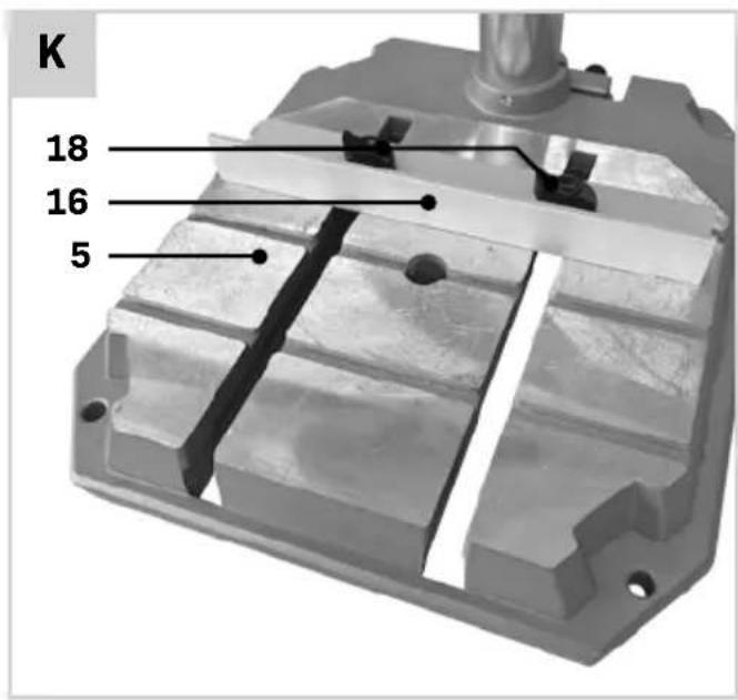
Mounting the parallel fence (Fig. J, K)

Risk of injury! It is forbidden to hold workpieces by hand as this is dangerous. The parallel fence can only be used in conjunction with the quick-action clamp or a similar clamping device. It is not allowed to use the fence and hold the workpiece by hand.
- Start by loosely hand-tightening the knobs (18) and square nuts (17) to the fence (16), as shown on figure J.
-
Now slide the fence (16) into the grooves of the baseplate (5) as shown on figure K.
-
Put the fence (16) in the desired position and tighten the knobs (18) by hand.
- The fence (16) position can easily be adjusted by loosening the knobs (18) and tightening them again afterwards.
Install of a stationary machine (Fig. A, B)
To ensure safe handling, the power tool must be mounted on a flat, stable work surface (e.g. work bench) before use. You can install the machine in two ways:
1. On a workbench
In this case the machine must be secured to the workbench using suitable screw fasteners. Use the four holes (24) in the baseplate (5) to do this. As shown on fig. D.
2. On a subframe

Read all the warnings and instructions included with the stand. Failure to observe the warnings and follow instructions may result in electric shock, fire and/or serious injury.

Assemble the stand properly before mounting the power tool. Correct assembly is important to prevent the risk of collapsing.
In this case the machine must be secured to the sub frame with bolts. Use the four holes (24) in the baseplate (5) to do this. The sub frame must be anchored with 4 bolts to the floor plate with dimensions of at least 1 square meter.
4. OPERATION

Always check the protective guards before use.

Check the drill and its safety devices for damage and impairments. Do not use the drill if you discover any damage or impairments and contact Vonroc customer service.

Ensure that the voltage of the mains supply complies with the specifications on the rating plate.

Connect the machine only to a socket with the properly installed earthing contact.

Avoid dust accumulation at the workplace. Dust can easily ignite.

After each adjustment to the power tool, firmly retighten all screws and clamping levers.
Mounting and removing a drill (fig. A)
Drill bits and other tool accessories with a round shaft diameter of 1.5-13mm can be clamped in the chuck (26) of the pillar drill.
- Insert the drill bit (22) into the chuck and hold it in position. Note: When using small drill bits, adjust the tool holder to the rough drilling diameter first. Otherwise, there is a risk that the drill bit will not be centred properly.
- Fix the drill bit by tightening the lower sleeve of the chuck (27) counter-clockwise by hand. Note: the direction of rotation is also marked on the clamping ring with "LOCK" along with the direction of rotation.
- Secure the drill bit by holding the upper sleeve of the chuck (28) and tightening the lower sleeve of the chuck (27) in counter-clockwise direction. The chuck makes a clicking noise for each rotation which indicates the locking.
- To remove the drill bit, open the chuck by holding upper sleeve of the chuck (28) and loosening the lower sleeve of the chuck (27) by turning it clockwise. Note: the direction of rotation is also marked on the clamping ring with "UNLOCK" along with the direction of rotation.
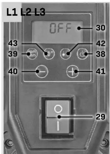
Switching on and off (Fig. A, L)
The table drill is equipped with a no-volt trip that is designed to protect the operator from an undesired restart following a drop in voltage. Should this occur, the machine must be manually restarted.
Switching on
- To switch on the display (30), press the (I) button on the On/Off switch (29).
- To switch on the power tool, press the power button (38).
Switching off
- To stop drilling, press the power button (38).
- To switch off the power tool completely, press the (0) button on the On/Off switch (29).
Note: the power tool is now switched off. All current settings are deleted.
Or
- The power tool can be quickly switched off, for example, if the application tool becomes jammed in the work-piece. Press the (0) button on the On/Off switch (29) to switch off the power tool and the display immediately.
Note: the power tool is now switched off. All current settings are deleted.
Adjusting the speed (Fig. A,L)

If an incorrect rotational speed is selected, the application tool may become jammed in the workpiece.
The table drill is equipped with two mechanical gears and an electronic speed adjustment. Select the correct rotational speed before starting work. It must be appropriate for both the drilling diameter and the material you intend to drill. Use the speed diagram to help you set the appropriate rotational speed. It shows the speed that should be set (rpm) depending on the drill diameter (dia. in mm) for the materials Steel and Wood. Note: The drill speeds specified are merely suggested values.
Changing the gear (Fig. A)

Change speeds only when the drill spindle has come to a complete stop (risk of damage to the gears).
- Turn the gear selector (19) to position '1' for a no-load speed of 220 – 880 rpm. Generally speaking, this gear is for working with large drilling diameters.
- Turn the gear selector (19) to position '2' for a no-load speed of 650 – 2550 rpm. Generally speaking, this gear is for working with small drilling diameters.

Ensure the speed selection switch (19) properly locks into position 1 or 2.
Adjusting the speed (Fig. A, L)
The available speed range depends on the selected gear (see chapter "changing the gear").
- Ensure the display (30) is switched on by pressing the (l) button on the On/Off switch (29) and
activate the drill by pressing the power button (38).
- Wait for a few seconds until the drill reaches its current speed. You can observe the increasing speed on the display (30), see also figure L2.
- Press the “+” button (40) to increase the speed.
- Press the “-” button (41) to decrease the speed.
Switching the laser / LED worklight on or off (Fig. A, L)
- Ensure the display (30) is switched on by pressing the (I) button on the On/Off switch (29) and activate the drill by pressing the power button (38).
- Press the laser / LED worklight button (42) button repeatedly to switch between the Laser - Light - Laser / Light modes.
- The respective mode setting is shown on the display (30), see also figure L3.
- "Laser" = Cross laser switched on
- "Light" = LED work light is switched on
- "Laser & Light" = Cross laser and LED work light both switched on.
- To switch off, change the modes or press the laser / LED worklight button (42) several times until nothing is shown on the display.
Adjusting the laser (Fig. A, L)
Note: To test the laser function, the power tool must be connected to the power supply.

While adjusting the laser (e.g. when moving the tool arm), never activate the on/off switch. Accidental starting of the power tool can lead to injuries.
If the laser (20) ceases to indicate the correct cutting line, you can readjust the laser. To do so:
- Loosen the screw (44) and adjust the laser position.
- Tighten the screw (44).
Displaying the drilling depth or speed (fig. A, L)
By pressing the speed or depth selection button (39), the drilling speed or the drilling depth can be selected on the display (30).
- Ensure the display (30) is switched on by pressing the (l) button on the On/Off switch (29) and activate the drill by pressing the power button (38).
-
By default, the speed is shown on the display, as shown on Fig. L2.
-
Press the speed or depth selection button (39) to change the display to drilling depth, as shown on figure L4.
- Press the speed or depth selection button (39) again to change back to the speed display, as shown on figure L2.
Defining the drill depth zero point (fig. A, L)
- Ensure the display (30) is switched on by pressing the (I) button on the On/Off switch (29) and activate the drill by pressing the power button (38).
- Change the display to the drilling depth (see chapter "Displaying the drilling depth or speed").
- Move the machine head downwards when the drill bit is rotating using the drill depth handle (4). The display shows the deviation continuously from the current zero point.
- Stop at the desired position and press the zero point button (43) to define the current depth / height as the new zero point.
- The display shows the new starting point as "0.0".
Height adjustment (Fig. A, B)

Do not adjust the height of the drive unit during operation. Only operate clamping lever (36) when the drill depth handle (4) is in its initial position. This precautionary measure prevents potential injuries from occurring.
The position of the machine head can be adjusted depending on the height of the workpiece or the drill accessory length. Adjust the height of the machine head so that there is sufficient clearance between the tip of the drill bit (22) and the upper surface of the workpiece. A clearance of 15 mm is recommended.
- Loosen the clamping lever (36) at the back of the machine head with one turn in counter-clockwise direction.
- Crank the height adjustment lever (33) clockwise to move the machine head up.
- Crank the height adjustment lever (33) counterclockwise to move the machine head down.
-
The height adjustment cannot be moved any further once the upper or lower dead centre is reached.
-
Tighten the clamping lever (36) at the back of the machine head in clockwise direction.
- After adjusting the height of the drive unit, the position of the workpiece must be checked again using the laser cross. You may need to reposition the workpiece.
Note: the machine will only be firm and free of play (movement) once the clamping lever (36) is tightened.
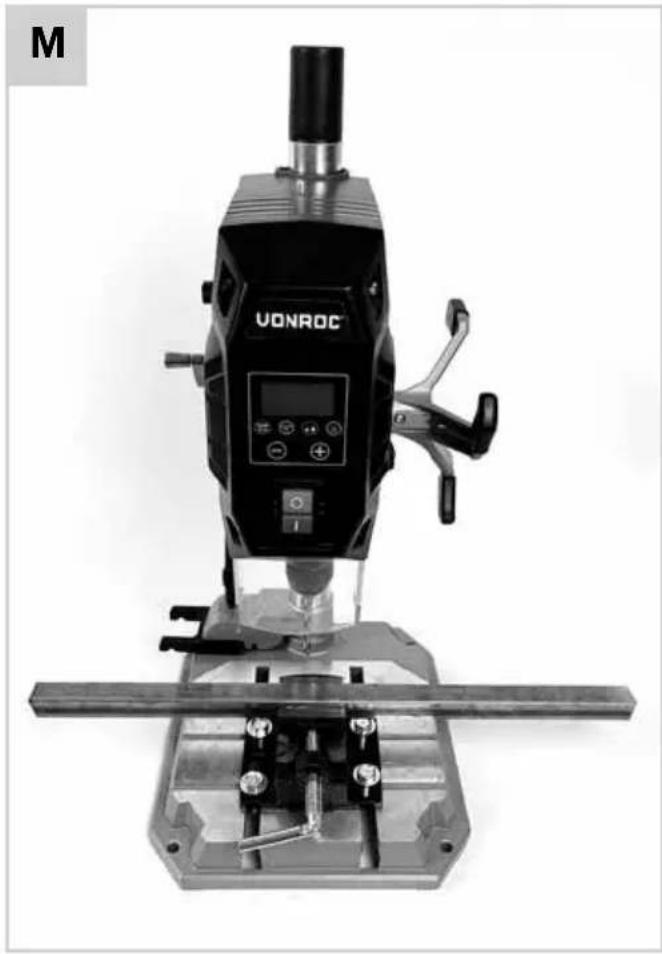
Clamping the workpiece (Fig. A, B, M, N, O)

Risk of injury! It is forbidden to hold workpieces by hand as this is dangerous. Always secure the workpiece in a machine vice or a similar clamping device.

The workpiece being machined has to be securely clamped. Do not machine any workpieces that cannot be clamped, for example if they are too small.

The free end of long and heavy workpieces must have something placed underneath it or be supported.
The pillar drill is provided with a quick-action clamp (9), parallel fence (16) and a machine vice (11) that all can be used to properly clamp a workpiece.
Clamping a workpiece using the machine vice
The machine vice can be used for diverse clamping applications, and is ideally suited for clamping small(er) workpieces.
- Mount the machine vice (11) as explained in chapter "Mounting the machine vice".
- Loosen the clamping lever (25) by turning it in counter-clockwise direction.
- Position the workpiece by referring to the laser cross.
- Tighten the clamping lever (25) in clockwise direction until the workpiece is tightly clamped.
- After drilling, release the clamping lever (25) by turning it anticlockwise.
Clamping a workpiece using the quick-action clamp The quick-action clamp can be used for diverse clamping applications, and is ideally suited for clamping round or tubular materials, as well as sheet metal and wooden boards.
- Mount the quick-action clamp (9) as explained in chapter "Mounting the quick-action clamp".
- Loosen the clamping lever (10) by turning it in counter-clockwise direction.
- Position the workpiece by referring to the laser cross.
- Allow the quick-action clamp (9) to rest on the workpiece. Refer to figure N as an example.
- Tighten the clamping lever (10) in clockwise direction until the workpiece is tightly clamped.
- After drilling, release the clamping lever (10) by turning it anticlockwise. Turn the quick-action clamp (9) to the side and remove the workpiece.
Clamping a workpiece using the quick-action clamp in conjunction with the parallel guide

Risk of injury! It is forbidden to hold workpieces by hand as this is dangerous. The parallel fence can only be used in conjunction with the quick-action clamp or a similar clamping device. It is not allowed to use the fence and hold the workpiece by hand.
The parallel fence (16) is used to prevent large workpieces from twisting. It can only be used in conjunction with the quick-action clamp, it is not possible to use it with the machine vice.
- Mount the parallel fence (16) as explained in chapter "Mounting the parallel guide".
- Use the quick-action clamp to secure the workpiece. Refer to: "Clamping a workpiece using the quick-action clamp".
Adjusting the depth stop (fig. B)
The depth stop can be adjusted, to limit the drilling depth.
- Loosen the knob (31) of the drilling depth stop, see also figure B.
- Set the depth stop to the desired depth, using the depth scale (32).
- Clamp the workpiece in the vice (see chapter "Clamping the workpiece").
- Adjust the height of the machine head (see chapter "Height adjustment").
- Place the drill tip lightly on the workpiece and define the zero point (see chapter "Defining the drill depth zero point").
-
Carry out a test drilling.
-
Once the desired depth is shown in the display (30), tighten the knob (31) of the drilling depth stop firmly.
- The depth stop is now locked at the desired drilling depth.
Drilling

Risk of damage! Allow the pillar drill to cool down to room temperature after using it for 15 minutes before working further.

The drill can become jammed in the workpiece when it is being removed from the workpiece, which may cause kickback. Therefore, make sure to slow down the feed motion towards the end of the drilling procedure.

Always stand in front of the power tool. This will ensure you always have a good view of the drilling point. Keep hands and fingers away from the rotating application tool. Do not reach one arm across the other when in front of the drive unit.
- Prepare the pillar drill and the workpiece as described in the preceding chapters.
- Make sure that the protective guard (7) is lowered down. An example of a properly positioned guard is shown on figure A.
- Align the workpiece and clamp it (see chapter "Clamping the workpiece").
- Connect the pillar drill to the power supply.
- Switch on the pillar drill (see chapter "Switching on / off").
- For drilling, move the drill depth handle (4) with uniform feed, until the desired drilling depth is reached. Note: when drilling metals, briefly interrupt the feed to break the chips.
- After reaching the drilling depth, move the drill depth handle (4) back to its initial position.
- Switch the pillar drill off.
Optimum use
- The drill feed, movement of the drill bit, is done manually using the drill depth handle (4)
- The cutting rate is influenced by the drilling speed and the bit diameter.
-
The service life of drill bits is largely determined by the feed speed and the spindle speed. As a general rule: Select a lower speed for large diameter drill bits.
-
For metal workpieces, reduce the feed rate and cutting speed and cool the drill bit using drilling oil. Metal workpieces should be centre-punched before drilling into them.
- For larger holes in thin sheets, use a low feed rate and cutting pressure so that the drill bit does not get “stuck” and the bore is dimensionally accurate.
- Effective chip ejection is hindered and the drill bit becomes warmer when drilling deep holes (deeper than 2 times the drill bit diameter). Reduce the feed rate and drilling speed and retract the bit from the hole repeatedly to improve chip ejection.
- When drilling holes over 8 mm in diameter pre-drilling is advisable to prevent premature wear and stress on the drill tip.
Transport
When transporting the pillar drill tool, hold it with both hands on the baseplate (5) or with one hand on the main drill housing (1). Do not carry the power tool by the drill depth handle (4).
5. MAINTENANCE

Before cleaning and maintenance, always switch off the machine and unplug the power cord.
Clean the machine casings regularly with a soft cloth, preferably after each use. Make sure that the ventilation openings are free of dust and dirt. Remove very persistent dirt using a soft cloth moistened with soapsuds. Do not use any solvents such as gasoline, alcohol, ammonia, etc. Chemicals such as these will damage the synthetic components.
ENVIRONMENT

ulty and/or discarded electrical or electronic apparatus have to be collected at the appropriate recycling locations.
Only for EC countries
Do not dispose of power tools into domestic waste. According to the European Guideline 2012/19/EU for Waste Electrical and Electronic Equipment and its implementation into national right, power tools that are no longer usable must be collected separately and disposed of in an environmentally friendly way.
WARRANTY
VONROC products are developed to the highest quality standards and are guaranteed free of defects in both materials and workmanship for the period lawfully stipulated starting from the date of original purchase. Should the product develop any failure during this period due to defective material and/or workmanship then contact VONROC directly.
The following circumstances are excluded from this guarantee:
- Repairs and or alterations have been made or attempted to the machine by unauthorized service centers;
- Normal wear and tear;
- The tool has been abused, misused or improperly maintained;
- Non-original spare parts have been used.
This constitutes the sole warranty made by company either expressed or implied. There are no other warranties expressed or implied which extend beyond the face hereof, herein, including the implied warranties of merchantability and fitness for a particular purpose. In no event shall VONROC be liable for any incidental or consequential damages. The dealers remedies shall be limited to repair or replacement of nonconforming units or parts.
The product and the user manual are subject to change. Specifications can be changed without further notice.
Rotation, links/rechts.

Gehörschutz tragen.

Atemschutz tragen.

Augenschutz tragen.

2. INFORMATIE OVER HET APPARAAT
Bedoeld gebruik
DECLARATION OF CONFORMITY PD501AC - PILLAR DRILL
(EN) We declare under our sole responsibility that this product is in conformity with directive 2011/65/EU of the European parliament and of the council of 8 June on the restriction of the use of certain hazardous substances in electrical and electronic equipment is in conformity and accordance with the following standards and regulations:
(DE) Der Hersteller erklärt eigenverantwortlich, dass dieses Produkt der Direktive 2011/65/EU des Europäischen Parlaments und des Rats vom 8. Juni 2011 über die Einschränkung der Anwendung von bestimmten gefährlichen Stoffen in elektrischen und elektronischen Geräten entspricht. den folgenden Standards und Vorschriften entspricht:
(NL) Wij verklaren onder onze volledige verantwoordelijkheid dat dit product voldoet aan de conform Richtlijn 2011/65/EU van het Europees Parlement en de Raad van 8 juni 2011 betreffende beperking van het gebruik van bepaalde gevaarlijke stoffen in elektrische en elektronische apparatuur en in overeenstemming is met de volgende standaarden en reguleringen:
(FR) Nous déclarons sous notre seule responsabilité que ce produit est conforme aux standards et directives suivants: est conforme à la Directive 2011/65/EU du Parlement Européen et du Conseil du 8 juin 2011 concernant la limitation d'usage de certaines substances dangereuses dans l'équipement électrique et électronique.
(ES) Declaramos bajo nuestra exclusiva responsabilidad que este producto cumple con las siguientes normas y estándares de funcionamiento: se encuentra conforme con la Directiva 2011/65/UE del Parlamento Europeo y del Consejo de 8 de junio de 2011 sobre la restricción del uso de determinadas sustancias peligrosas en los equipos eléctricos y electrónicos.
(IT) Dichiariamo, sotto la nostra responsabilità, che questo prodotto è conforme alle normative e ai regolamenti seguenti: è conforme alla Direttiva 2011/65/UE del Parlamento Europeo e del Consiglio dell'8 giugno 2011 sulla limitazione dell'uso di determinate sostanze pericolose nelle apparecchiature elettriche ed elettroniche.
(SV) Vi garanterar på eget ansvar att denna produkt upp fyller och följer följande standarder och bestämmelser: uppfyller direktiv 2011/65/EU från Europeiska parlamentet och EG-rådet från den 8 juni 2011 om begränsningen av användning av farliga substanser i elektrisk och elektronisk utrustning.