
FMXCMD152WE - Compressor STANLEY - Free user manual and instructions
Find the device manual for free FMXCMD152WE STANLEY in PDF.
| Product type | Wall-mounted air compressor |
| Brand | STANLEY |
| Model | FMXCMD152WE |
| Power supply | 230 V / 50 Hz (estimated) |
| Maximum operating pressure | Refer to compressor label |
| Tank capacity | Refer to compressor label |
| Air flow | Refer to compressor label |
| Guaranteed sound power level | Refer to compressor label |
| Tank type | Steel |
| Integrated hose reel | Yes, with automatic locking |
| Pressure gauge | Indicates tank pressure |
| Condensate drain valve | Yes, located at bottom of tank |
| Safety valve | Yes, factory set at maximum pressure |
| Thermal protection | Yes, automatic shutdown in case of overheating |
| Automatic shut-off | Yes, when maximum pressure is reached |
| Starting type | Manual via I/O switch |
| Operating temperature | Between +5°C and +40°C |
| Intended use | Domestic, for pneumatic tools |
| Air filter maintenance | Every 100 hours of operation |
| Condensate draining | Every day and at end of work |
| Wall mounting | Yes, includes 4 rubber spacers |
Frequently Asked Questions - FMXCMD152WE STANLEY
User questions about FMXCMD152WE STANLEY
0 question about this device. Answer the ones you know or ask your own.
Ask a new question about this device
Download the instructions for your Compressor in PDF format for free! Find your manual FMXCMD152WE - STANLEY and take your electronic device back in hand. On this page are published all the documents necessary for the use of your device. FMXCMD152WE by STANLEY.
USER MANUAL FMXCMD152WE STANLEY
Stanley® and the Stanley logo are registered trade marks of Stanley Black & Decker, Inc. or an affiliate thereof and are used under license.
Manufactured by:
FNA S.p.A. - Via Einaudi 6, Robassomero (TO) Italy.
Attenzione! - Warning! - Attention! - Achtung! - ¡Cuidado! - Atenção! - Waarschuwing! - Advarsel! - Varning! - Varoitus! - Прогохή! - Uwaga! - Pozor! - Pozor! - Figyelem! - Pozor! - Pozor! - Внимание! - Advarsel! - Uyari! - Atenție! - Внимание! - Pažnja! - Dėmesio! - Tähelepanu! - Uzmanību!
IT Tutti i dati identificativi, costruttore, modello, codice e numero di serie, sono riportati sull'etichetta CE applicata sull'ultima pagina del manuale.
GB All identification data: manufacturer, model, code and serial number are printed on EC label stuck onto the last page of this manual.
FR Toutes les données d'identification : fabricant, modèle, référence et numéro de série, sont indiquées sur l'étiquette CE appliquée sur la dernière page du manuel.
DE Sämtliche Gerätedaten wie Hersteller, Modell, Artikel- und Seriennummer sind auf der CE-Plakette angeführt, die auf der letzten Seite des Handbuchs abgebildet ist.
ES Todos los datos identificativos: fabricante, modelo, código y número de serie figuran en la etiqueta CE aplicada en la última página del manual.
PT Todos os dados de identificação: fabricante, modelo, código e número de série são impressos na etiqueta CE colada na última página deste manual.
NL Alle identificatiegegevens: fabrikant, model, code en serienummer zijn gedrukt op het EG-etiket dat is aangebracht op de laatste pagina van deze handleiding.
DK Alle identifikationsoplysninger: Producent, model, kode og serienummer findes på CE-mærkaten, der er anbragt på sidste side i denne manual.
SE Alla identifieringsdata, tillverkare, modell, kod och serienummer, återges i CE-märkningen, som sitter på sista sidan i manualen.
FI Kaikki tunnistustiedot, kuten valmistaja, malli, koodi ja sarjanumero löytyvät oppaan viimeisellä sivulla olevasta CE-merkinnästä.
GR Όλα τα στοιχεία ταυτότητας, κατασκευαστής, μοντέλο, κωδικός, και αριθμός σειράς, αναφέρονται στην ετικέτα CE που βρίσκεται στην τελευταία σελίδα του εγχειρίδιου χρήσης.
PL Wszystkie dane identyfikacyjne: producent, model, kod i numer seryjny zostały wskazane na oznaczeniu CE przyklejonym na ostatniej stronie niniejszej instrukcji.
HR Svi identifikacijski podaci: proizvođač, model, šifra i serijski broj su ispisani na CE etiketi koja se nalazi na posljednjoj stranici ovog priručnika.
SI Vsi identifikacijski podatki, proizvajalec, model, koda in serijska številka, so navedeni na CE oznaki, ki se nahaja na zadnji strani priročnika.
HU Az azonosításhoz szükséges adatok, úgymint gyártó, modell, kód és sorozatszám, megtalálhatók a kézikönyv utolsó oldalára ragasztott EK-címkén.
CZ Všechny identifikační údaje (výrobce, model, kód a sériové číslo) jsou vytištěny na štítku EK nalepeném na poslední straně této příručky.
SK Všetky identifikačné údaje (výrobca, model, kód a sériové číslo) sú vytlačené na štítku EK nalepenom na poslednej strane tejto príručky.
RU Все идентификационные данные, название производителя, модель, номер и серийный номер указаны на этикетке СЕ, наклеенной на последней странице руководства.
NO Alle identifikasjonsdata: Produsent, modell, kode og serienummer er trykt på EU-merket som du finner på den siste siden i denne bruksanvisningen.
TR Tüm kimlik verileri: üretici, model, kod ve seri numarası, bu kılavuzun son sayfasına yapıştırılmış olan AT etiketi üzerine basılmıştır.
RO Toate datele de identificare, producătorul, modelul, codul și numărul de serie sunt redate pe eticheta CE aplicată pe ultima pagină a manualului.
BG Всички идентификационни данни - производител, модел, код и сериен номер - са отпечатани върху СЕ маркировката на последната страница на настоящото ръководство.
RS Svi identifikacijski podaci: proizvođač, model, šifra i serijski broj su ispisani na CE etiketi koja se nakazi na zadnjoj strani ovog priručnika.
LT Visi identifikaciniai duomenys: gamintojas, modelis, kodas ir serijos numeris, yra išspausdinti EB etiketėje, priklijuotoje paskutiniame šio vadovo puslapyje.
EE Kõik identifitseerimisandmed, nagu tootja, mudel, kood ja seerianumber, on trükitud toote tagaküljel olevale EÜ märgistusele.
LV Visi identifikacijas dati: ražotājs, modelis, kods un sērijas numurs ir drukāti uz EK etiketes, kas pielīmēta šīs rokasgrāmatas pēdējā lapā.
(IT) Dichiarazione di conformità CE - (GB) Declaration of conformity EC - (FR) Déclaration de conformité CE - (DE) EG Konformitätserklärung - (ES) Declaración de conformidad CE - (PT) Declaração de conformidade CE - (NL) Verklaring van overeenstemming EEG - (DK) CE-Overensstemmelseserklæring - (SE) Försäkran om CE-överensstämmelse - (FI) CE Vaatimustenmukaisuusvakuutus - (GR) Δηλωση συμμορφωσης CE - (PL) Deklaracja zgodności WE - (HR) Izjava o sukladnosti direktivama EZ - (SI) Izjava o skladnosti ES - (HU) EK Megfelelési nyilatkozat - (CZ) ES Prohlášení o shodě - (SK) Prehlásenie ES o zhode - (RU) Декларация о соответствии нормам EO - (NO) EF-overensstemmelseserklæring - (TR) AT uygunluk beyanı - (RO) Declaratie de conformitate CE - (BG) Декларация за съответствие по стандарт на EO - (RS) Izjava o sukladnosti propisima EZ - (LT) Deklaracija dėl EB reikalavimų vykdymų - (EE) Vastavusdeklaratsioon EK - (LV) Paziņojums par atbilstību EK prasībām
La seguente dichiarazione è allegata in copia originale al compressore - The following declaration is attached to the compressor in original copy - La déclaration suivante est jointe en copie originale au compresseur - Die gegenständliche Erklärung wird im Original dem Kompressor beigepackt - La siguiente declaración se adjunta en copia original al compresor - A seguinte declaração está anexada ao compressor na cópia original - Een originele kopie van de onderhavige verklaring is bij de compressor gevoegd - Denne erklæring vedlægges kompressoren i försteeksemplar - Följande försäkran bifogas kompressorn i originalkopia - Seuraava vakuutus on liitetty kompressoriin alkuperäisenä kopiona - Auθεντικό αντίτυπο της παρακάτω δήλωσης προσαρτάται στον συμπιεστή - Oryginal niniejszej deklaracji jest dolączony do sprężarki - Uz kompresor je priložena kopija originala sljedeće izjave - Ta izjava je v originalu priložena kompresorju - Az alábbi nyilatkozat eredeti példánya a kompresszor mellékletét képezi - Následující prohlášení je přiloženo ke kompresoru v originální kopii - Nasledujúce vyhlásenie je priložené ku kompresoru v originálnej kópii - Оригинал декларации прилагается к компрессору - Den følgende erklæringen er festet til kompressoren i original kopi - Aşağıdaki beyan, orijinal nǚsha olarak kompresöre iliştirilmiştir - Urmâtoarea declarație este anexată în copie originală la compresor - Оригинално копие на следната декларация е прикрепена към компресора - Uz kompresor je priložena kopija originala sledeće izjave - Toliau pateiktos deklaracijos originali kopija pritvirtinta prie kompresoriaus - Selle avalduse originaaleksemplar on kinnitatud kompressorile - Sekojošās deklarācijas originālā kopija ir pievienota kompresoram
STANLEY
Stanley ^® and the Stanley logo are registered trade marks of Stanley Black & Decker, Inc. or an affiliate thereof and are used under license.
Manufactured by:
FNA S.p.A. - Via Einaudi 6, Robassomero (TO) Italy.
| IT | Dichiara sotto la sua esclusiva responsabilità, che il compressore d'aria qui di seguito descritto è conforme a tutte le disposizioni pertinenti delle seguenti direttive comunitarie: 2006/42/CE, 2000/14/CE, 2014/30/UE, 2011/65/UESono state applicate le seguenti norme armonizzate nell'ultima versione pubblicata sulla Gazzetta Ufficiale Europea:EN 1012-1, EN 60204-1, EN 55014-1, EN 55014-2, EN 61000-3-2, EN 61000-3-3 |
| GB | Declares under its sole responsibility that the air compressor described below complies with all relevant regulations of the following EU directives: 2006/42/EC, 2000/14/EC, 2014/30/EU, 2011/65/EUThe following harmonised standards have been applied in the latest version published on the Official Journal of the European Union:EN 1012-1, EN 60204-1, EN 55014-1, EN 55014-2, EN 61000-3-2, EN 61000-3-3 |
| FR | Déclare sous son entière responsabilité que le compresseur d'air décrit ci-après est conforme à toutes les dispositions pertinentes des directives communautaires suivantes: 2006/42/CE, 2000/14/CE, 2014/30/UE, 2011/65/UELes normes suivantes harmonisées dans la dernière version publiée au Journal Officiel de l'Union Européenne ont été appliquées:EN 1012-1, EN 60204-1, EN 55014-1, EN 55014-2, EN 61000-3-2, EN 61000-3-3 |
| DE | Erklärt unter ihrer alleinigen Verantwortung, dass der in Folge beschriebene Luftkompressor allen einschlägigen Bestimmungen der folgenden EU-Richtlinien entspricht: 2006/42/EG, 2000/14/EG, 2014/30/EU, 2011/65/EUDie folgenden Harmonisierten Normen wurden in der jüngsten im Amtsblatt der Europäischen Union veröffentlichten Version angewendet:EN 1012-1, EN 60204-1, EN 55014-1, EN 55014-2, EN 61000-3-2, EN 61000-3-3 |
| ES | Declara, bajo su exclusiva responsabilidad, que el compresor de aire descrito a continuación responde a todas las disposiciones pertinentes de las siguientes directivas comunitarias: 2006/42/CE, 2000/14/CE, 2014/30/UE, 2011/65/UESe han aplicado las siguientes normas armonizadas en la última versión publicada en el Diario Oficial de la Unión Europea:EN 1012-1, EN 60204-1, EN 55014-1, EN 55014-2, EN 61000-3-2, EN 61000-3-3 |
| PT | Declara sob a sua exclusiva responsabilidade que o compressor de ar descrito a seguir está em conformidade com todas as normas relevantes das seguintes directivas da UE: 2006/42/CE, 2000/14/CE, 2014/30/UE, 2011/65/UEAs seguintes normas harmonizadas foram aplicadas na última versão publicada no Jornal Oficial da União Europeia:EN 1012-1, EN 60204-1, EN 55014-1, EN 55014-2, EN 61000-3-2, EN 61000-3-3 |
| NL | Verklaart onder zijnigen verantwoordelijkheid dat de hieronder beschreven persluchtcompressor voldoet aan alle voorschriften van de volgende EG-richtlijnen: 2006/42/EG, 2000/14/EG, 2014/30/EU, 2011/65/EUDe volgende geharmoniseerde standaards zijn toegepast in de laatste versie gepubliceerd in het Publicatieblad van de Europese Unie:EN 1012-1, EN 60204-1, EN 55014-1, EN 55014-2, EN 61000-3-2, EN 61000-3-3 |
| DK | Erklærer under eget ansvar, at luftkompressoren, der beskrives nedenfor, er i overensstemmelse med alle relevante forordninger fra de følgende EU-direktiver: 2006/42/EC, 2000/14/EC, 2014/30/EU, 2011/65/EUDe følgende harmoniserede standarder gør sig gældende for den seneste version, som er offentliggjort i De Europæiske Fællesskabers Tidende: EN 1012-1, EN 60204-1, EN 55014-1, EN 55014-2, EN 61000-3-2, EN 61000-3-3 |
| SE | Försäkrar under eget ansvar att den luftkompressor som beskrivs nedan överensstämmer med alla tillhörande föreskrifter i följande EG-direktiv: 2006/42/EG, 2000/14/EG, 2014/30/EU, 2011/65/EUFöljande harmoniserade standarder har tillämpats i den senaste versionen, som publicerats i den Europeiska unionens officiella tidning: EN 1012-1, EN 60204-1, EN 55014-1, EN 55014-2, EN 61000-3-2, EN 61000-3-3 |
| FI | Vakuuttaa omalla vastuillaan, että seuraavassa esitelty ilmakompressori vastaa kaikkia seuraavien Euroopan direktiivien vaatimuksia: 2006/42/EY, 2000/14/EY, 2014/30/EU, 2011/65/EUSeuraavia harmonisoituja normeja, joiden viimeisin versio on julkaistu Euroopan unionin virallisessa lehdessä, on sovellettu: EN 1012-1, EN 60204-1, EN 55014-1, EN 55014-2, EN 61000-3-2, EN 61000-3-3 |
| GR | Δηλώνει με αποκλειστική δική της ευθύνη, ότι ο συμπιεστής αέρος που περιγράφεται παρακάτω συμμορφώνεται με όλες τις σχετικές διατάξεις των εξής κοινοτικών οδηγιών: 2006/42/EK, 2000/14/EK, 2014/30/EE, 2011/65/EEΕφαρμόστηκαν οι εξής εναρμονισμένοι κανονισμοί στην τελευταία έκδοση της Επίσημης Εφημερίδας των Ευρωπαϊκών Κοινοτήτων: EN 1012-1, EN 60204-1, EN 55014-1, EN 55014-2, EN 61000-3-2, EN 61000-3-3 |
| PL | Oświadcza na swoją wyłącznie odpowiedzialność, że opisana poniżej sprežarka spełnia wszystkie stosowne przepisy zawarte w następujących dyrektywach Unii Europejskiej: 2006/42/EC, 2000/14/EC, 2014/30/UE, 2011/65/UENastępujące ujednolicone normy mają zastosowanie w najbardziej aktualnej wersji opublikowanej w Dzienniku Urzędowym Unii Europejskiej: EN 1012-1, EN 60204-1, EN 55014-1, EN 55014-2, EN 61000-3-2, EN 61000-3-3 |
| HR | Izjavljuje pod vlastitom odgovornošću da dolje opisani kompressor zraka udovoljava svim važećim propisima sljedećih Direktiva EU: 2006/42/EZ, 2000/14/EZ, 2014/30/EU, 2011/65/EUSlijedeće usklađene norme primjenjuju se u najnovijoj verziji objavljenoj u Službenom listu Europske unije: EN 1012-1, EN 60204-1, EN 55014-1, EN 55014-2, EN 61000-3-2, EN 61000-3-3 |
| SI | Izjavlja pod lastno odgovornostjo, da je v nadaljevanju opisan kompressor za zrak skladen z vsemi določili s področja naslednjih direktiv skupnosti: 2006/42/EU, 2000/14/EU, 2014/30/EU, 2011/65/EUUveljavljeni so naslednji harmonizirani standardi zadnje verzije, objavljene v Uradnem listu Evropske skupnosti: EN 1012-1, EN 60204-1, EN 55014-1, EN 55014-2, EN 61000-3-2, EN 61000-3-3 |
| HU | Kizárólagos felelőssége tudatában kijelenti, hogy a lent megnevezett kompresszor megfelel a következő EU irányelvek vonatkozó rendelkezéseinek: 2006/42/EK, 2000/14/EK, 2014/30/EU, 2011/65/EUAz alábbi harmonizált szabványokat az Európai Unió Hivatalos Lapjában közzétett legutóbbi változatuk szerint alkalmaztuk: EN 1012-1, EN 60204-1, EN 55014-1, EN 55014-2, EN 61000-3-2, EN 61000-3-3 |
| CZ | Prohlašuje s plnou odpovědností, že uvedený vzduchový kompressor splňuje všechna příslušná nařízení následujících směrnic EU: 2006/42/ES, 2000/14/ES, 2014/30/EU, 2011/65/EUPoužity byly následující harmonizované normy publikované v Úředním věstníku Evropské unie v nejnovějších verzích: EN 1012-1, EN 60204-1, EN 55014-1, EN 55014-2, EN 61000-3-2, EN 61000-3-3 |
| SK | Vyhlasuje na vlastnú zodpovednosť, že uvedený vzduchový kompressor splňa všetky príslušné nariadenia nasledujúcich smerníc EÚ: 2006/42/ES, 2000/14/ES, 2014/30/EÚ, 2011/65/EUBoli použité nasledujúce harmonizované normy publikované v Úradnom vestníku Európskej únie v najnovších verziách: EN 1012-1, EN 60204-1, EN 55014-1, EN 55014-2, EN 61000-3-2, EN 61000-3-3 |
| RU | Заявляет под свою исключительную ответственность, что воздушный компрессор, описанный ниже, отвечает всем соответствующим положениям следующих европейских директив: 2006/42/EC, 2000/14/EC, 2014/30/EU, 2011/65/EUCледующие гармонизированные стандарты были применены в последней редакции, опубликованной в правительственном вестнике EC: EN 1012-1, EN 60204-1, EN 55014-1, EN 55014-2, EN 61000-3-2, EN 61000-3-3 |
| NO | Erklærer under eget ansvar at luftkompressoren her beskrevet er i overensstemmelse med alle krav i de følgende EU-forskriftene: 2006/42/EC, 2000/14/EC, 2014/30/EU, 2011/65/EUDe følgende harmoniserte standardene er brukt i den siste versjonen trykt i den Den europeiske unions tidende (EUT): EN 1012-1, EN 60204-1, EN 55014-1, EN 55014-2, EN 61000-3-2, EN 61000-3-3 |
| TR | Tek sorumluluk kendisinde olmak üzere, aşağıda açıklanan hava kompresörünün, izleyen AB direktiflerinin ilgili tüm yönetmeliklerine uygun olduğunu beyan eder: 2006/42/EC, 2000/14/EC, 2014/30/UE, 2011/65/EAAvrupa Birliği'nin Resmi Gazetesi'nde yayınlanan son sürümde, aşağıdaki uyumlulaştırlılmış standartlar uygulanmıştır: EN 1012-1, EN 60204-1, EN 55014-1, EN 55014-2, EN 61000-3-2, EN 61000-3-3 |
| RO | Declară pe propria răspundere că compresorul de aer descris în continuare este conform cu toate dispozitiile în materie ale următoarelor directive comunitare: 2006/42/CE, 2000/14/CE, 2014/30/UE, 2011/65/UEAu fost aplicate următoarele standarde armonizate în ultima versiune publicată în Jurnalul Oficial al Uniunii Europene: EN 1012-1, EN 60204-1, EN 55014-1, EN 55014-2, EN 61000-3-2, EN 61000-3-3 |
| BG | Декларира на собствена отговорност, че описаният по-долу въздушен компресор отоваря на всички съответни разпоредби на следните директиви на ЕС: 2006/42/EC, 2000/14/EC, 2014/30/EC, 2011/65/ECСледните хармонизирани стандарти са приложени в най-новото издание, публикувано в Официален вестник на Европейския съюз: EN 1012-1, EN 60204-1, EN 55014-1, EN 55014-2, EN 61000-3-2, EN 61000-3-3 |
| RS | Izjavljuje pod ličnom odgovornošću da je dole opisan kompressor vazduha u skladu sa svim važećim propisima sledećih Direktiva EU: 2006/42/EZ, 2000/14/EZ, 2014/30/EU, 2011/65/EUSledeče usklađene norme primenjuju se u najnovijoj verziji objavljenoj u Službenom glasniku Evropske unije: EN 1012-1, EN 60204-1, EN 55014-1, EN 55014-2, EN 61000-3-2, EN 61000-3-3 |
| LT | Su visa atsakomybe pareiškia, kad žemiau aprašytas oro kompresorius atitinka visus taikomus reglamentus, apibrėžtus šiose ES direktyvose: 2006/42/EB, 2000/14/EB, 2014/30/ES, 2011/65/ESToliau nurodyti darniejį standartai buvo pritaikyti naujausioje versijoje, publikuotoje Europos Sajungos oficialiajame leidinyje: EN 1012-1, EN 60204-1, EN 55014-1, EN 55014-2, EN 61000-3-2, EN 61000-3-3 |
| EE | Avaldab enda täieliku vastutusega, et järgnevalt kirjeldatud ôhukompressor vastab köigile järgmiste EL-i direktiivide eeskirjadele: 2006/42/EÜ, 2000/14/EÜ, 2014/30/EL, 2011/65/ELEuropa Liidu Teatajas avaldatud uusimas versioonis on kohaldatud järgmisi ühtlustatud standardeid: EN 1012-1, EN 60204-1, EN 55014-1, EN 55014-2, EN 61000-3-2, EN 61000-3-3 |
| LV | Pilnībā apstiprina, ka tālāk minētais gaisa kompresors atbilst visiem šādu ES direktīvu noteikumiem: 2006/42/EK, 2000/14/EK, 2014/30/ES, 2011/65/ESJaunākajai versijai, kas publicéta Eiropas Savienības oficiālajā laikrakstā, ir piemēroti šādi vienotie standarti: EN 1012-1, EN 60204-1, EN 55014-1, EN 55014-2, EN 61000-3-2, EN 61000-3-3 |
IT LEGENDA SEGNALETICA DI SICUREZZA SUI PRODOTTI
GB KEY TO PRODUCT SAFETY SIGNS
FR LEGENDE DES PICTOGRAMMES DE SECURITE FIGURANT SUR LES PRODUITS
NL VERKLARING WAARSCHUWINGSSYMBOLEN OP PRODUCTEN
DK SIGNATURFORKLARING TIL PRODUKTERNES SIKKERHEDSSKILTNING
SE FÖRKLARING TILL SÄKERHETSSYMBOLER PÅ PRODUKTERNA
GB Before use, read the handbook carefully
GB Warning, hot surfaces
GB Danger - automatic control (closed loop)
GB Hearing, sight and respiratory protection must be worn
GB Drain out the tank daily
GB Do not spray liquids near the compressor
1 - Manufacturer's data
2 - CE mark and WEEE symbol
3 - Type / Code / Serial Number
4 - Air displacement expressed in (l/min) and (cfm)
5 - Air delivered by the compressor expressed in (l/min) and (cfm)
6 - Maximum operating pressure (bar and PSI), tank capacity (l), rotations per minute (RPM), weight (kg)
7 - Guaranteed sound power level in dB(A); Measured sound power level in dB(A)
8 - Electric data: voltage (V), frequency (Hz), absorption (A), power in (kW) and (HP)
9 - Duty cycle
10 - Declaration of origin
11 - Year of production/manufacturing
FR Légende
natural_image
Illustration of various hand tools including a drill, gloves, screwdriver, and screwdriver (no text or symbols)(not included)
2
natural_image
Line drawing of a person installing or adjusting a wall-mounted electronic device, no text or symbols present3
4
5
I) wall plug ∅ 8 x 40 mm
(8×50mm-8×60mm)
II)
screws 5 x 50 mm
(5×60mm-5×70mm)
6
I)
II)
natural_image
Technical illustration of a mechanical component with no visible text or symbolsIII)
natural_image
Technical illustration of a mechanical component with a knob and gear mechanism (no text or symbols)7
natural_image
Line drawing of a stainless steel electric pump with a hand holding a drill bit (no text or symbols)8
Preserve this handbook for future reference.
Before using the compressor, read the instructions for use carefully and comply with the following safety precautions. Consult this handbook if you have any doubts regarding functioning.
Preserve all the documentation so that anyone who uses the compressor can consult this beforehand.
1. PRECAUTIONS
An ACOUSTIC PRESSURE value of 4 m. corresponds to the ACOUSTIC POWER value stated on the label located on the compressor, minus 20 dB.

This symbol indicates warnings to be read more using the product so as to prevent injury the user.

Warning!
Compressed air is a potentially dangerous form of energy; always take great care when using the compressor and its accessories.

Warning!
The compressor may restart when power is restored following a blackout.

THINGS TO DO
- The compressor must be used in a suitable environment (well ventilated with an ambient temperature of between +5°C and +40°C) and never in places affected by dust, acids, vapors, explosive or flammable gases.
- Keep the work area clear. Clear the work area of unnecessary tools.
- Always maintain a safety distance of at least 4 meters between the compressor and the work area.
- Insert the plug of the electric cable in a socket of suitable shape, voltage and frequency complying with current regulations.
- Use extension cables with a maximum length of 5 meters and of suitable cross-section.
- The use of extension cables of different length and also of adapters and multiple sockets should be avoided.
- If the supply cord is damaged, it must be replaced by the manufacturer, its service agent or similarly qualified persons in order to avoid a hazard.
- Always use the switch I/O to switch off the compressor.
- When the compressor is not in use, act on the I/O switch and put it in the switched off position "O" (OFF), then remove the plug from the power socket.
- At the end of each use, rewind the hose completely, putting it in its housing; this way the reel will be protected of unnecessary and prolonged tension.

THINGS NOT TO DO
- Never direct the jet of air towards persons, animals or your body. (Always wear safety goggles to protect your eyes against flying objects that may be lifted by the jet of air).
- Never direct the jet of liquids sprayed by tools connected to the compressor towards the compressor.
- Never use the appliance with bare feet or wet hands or feet.
- Never pull the power cable to disconnect the plug from the socket or to move the compressor.
- Never leave the appliance exposed to adverse weather conditions.
- Never transport the compressor with the receiver under pressure.
- Do not weld or machine the receiver. In the case of faults or rusting, replace the entire receiver.
- Never allow inexperienced persons to use the compressor. Keep children and animals at a distance from the work area.
- This appliance is not intended for use by persons (including children) with reduced physical, sensory or mental capabilities, or lack of experience and knowledge, unless they have been given supervision or instruction concerning the use of the appliance by a person responsible for their safety.
- Children should be supervised to ensure that they do not play with the appliance.
- Do not position flammable or Nylon®/fabric objects closed to and/or on the compressor.
- Do not clean the machine with flammable liquids or solvents. Use only a slightly damp cloth, making sure to have disconnected the plug from the power socket.
- The compressor must be used only for air compression. Do not use the compressor for any other type of gas.
- The compressed air produced by the compressor cannot not be used for pharmaceutical, food or medical purposes except after particular treatments and cannot be used to fill the air bottles of scuba divers.
- Do not cover the air vents on the compressor.
- Pay attention to the work being carried out. Use common sense. Do not stand on the compressor. Do not allow the compressor to operate unattended.
- Do not use the compressor placed on the floor.
- Do not put weights and/or objects on the compressor (e.g. flower pots, etc.).

THINGS YOU SHOULD KNOW
- To avoid overheating of the electric motor, this compressor is designed for intermittent operation as indicated on the technical dataplate (for example, S3 25 % means 2.5 minutes ON, 7.5 minutes OFF). In the case of overheating, the thermal cutout of the motor trips, automatically cutting off the power when the temperature is too high. The motor restarts automatically when normal temperature conditions are restored.
- All the compressors are fitted with a safety valve that is tripped in the case of malfunctioning of the pressure switch in order to assure machine safety.
The safety valve is set to avoid over-pressurization of the air tanks. This valve is factory pre-set and will not function unless tank pressure reaches this pressure. Do not attempt to adjust or eliminate this safety device.
Any adjustments to this valve could cause serious injury. If this device requires service or maintenance, see an Authorized Service Center. - The red notch on the pressure gauge refers to the maximum operating pressure of the tank. It does not refer to the adjusted pressure.
- When fitting a tool, the flow of air in output must be switched off.
- When using compressed air, you must know and comply with the safety precautions to be adopted for each type of application (inflation, blowing, pneumatic tools, etc.).
- Check that the air consumption and the maximum working pressure of the pneumatic tool and of the connecting hoses (with the compressor) to be used are compatible with the pressure set on the pressure regulator (not included) and with the quantity of air delivered by the compressor.
- The compressor's performance is guaranteed for operation between 0 and 1000 meters above the sea level.
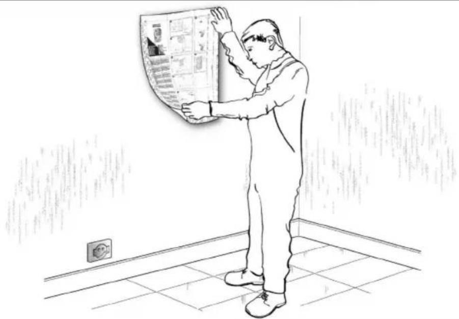
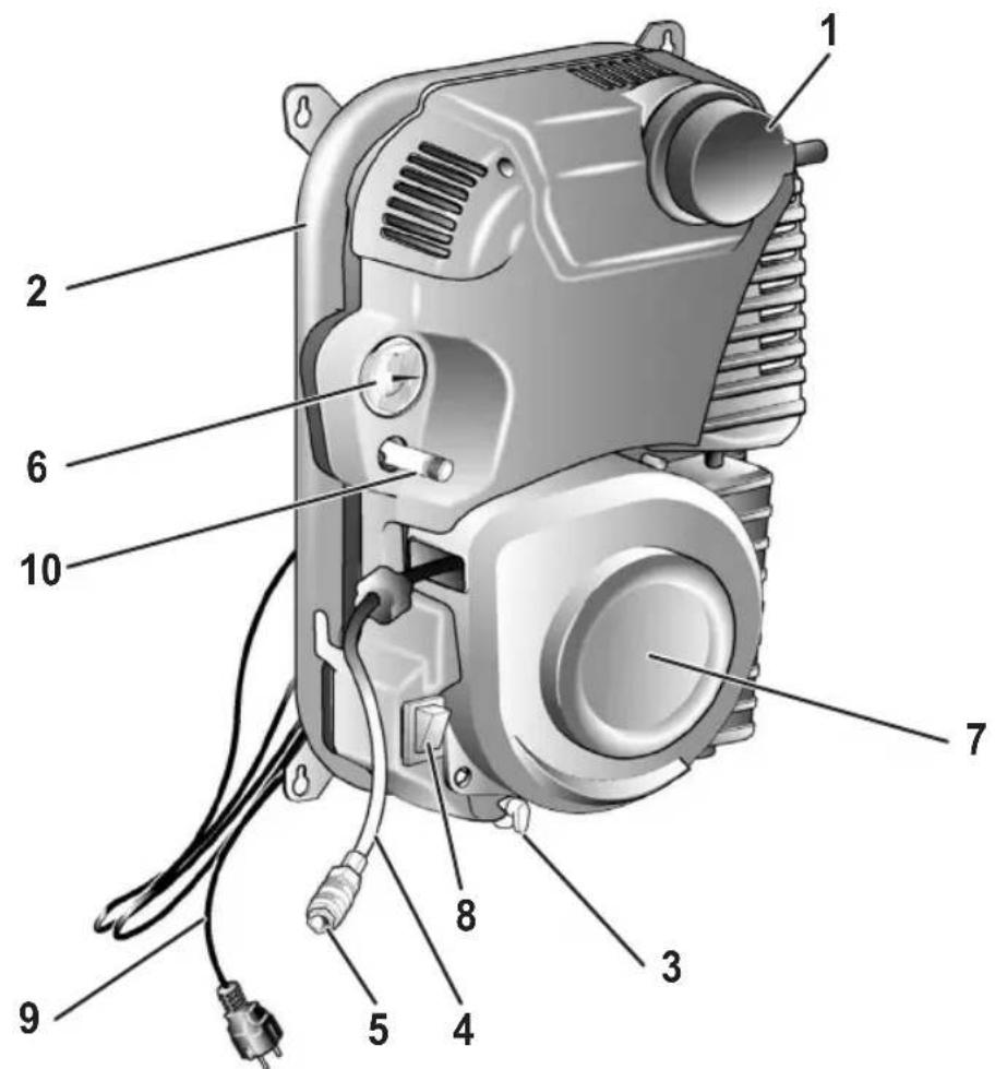
2. DESCRIPTION OF THE APPLIANCE (Fig. 8)
- Intake air filter
- Air receiver
- Tank condensate drain valve
- Air pipe
- Quick coupling
- Pressure gauge (indicates the tank pressure)
- Reel
- Switch I/O (ON/OFF)
- Power cord
- Safety valve
4. SCOPE OF USE
The compressor is designed for generating compressed air for tools operated by compressed air.
Please note that our equipment has not been designed for use in commercial, trade or industrial applications. Our warranty will be voided if the machine is used in commercial, trade or industrial businesses or for equivalent purposes.
The machine is to be used only for its prescribed purpose. Any other use is deemed to be a case of misuse. The user/operator and not the manufacturer will be liable for any damage or injuries of any kind caused as a result of this.
3. PACKAGING CONTENTS LIST
- Air compressor
- Assembly instruction sheet
- Rubber Spacers (4)
- Instruction manual and other documents
5. POINTS TO NOTE WHEN SETTING UP THE COMPRESSOR
- Examine the machine for signs of transit damage. Report any damage immediately to the company which delivered the compressor.
- The compressor should be set up near the working consumer.
- The use of extension cords is not recommended.
- Make sure the intake air is dry and dust-free.
- Do not set up the compressor in damp or wet rooms.
- The compressor may only be used in suitable rooms (with good ventilation and an ambient temperature from +5°C to +40°C). There must be no dust, acids, vapors, explosive gases or inflammable gases in the room.
- The compressor is designed to be used in dry rooms. It is prohibited to use the compressor in areas where work is conducted with sprayed water.

Attention!
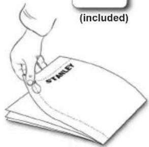
This compressor shall only be used fixed to a wall suitable to support its weight; it is forbidden to use the compressor in any other configuration.
6. INSTALLATION
After removing the compressor from the packaging and checking its integrity, make sure that all the components listed in the “packaging contents list” are present inside the packaging.
Before starting the installation of the compressor, it is necessary to obtain the materials and/or tools shown in figure 1 (NOT supplied), more precisely:
- Measuring tape,
- Adhesive tape,
- Scissors,
– Spirit level, - Drill/screwdriver,
– Cross head screwdriver, - Screws (4),
- Expansion plugs (4).

Warning!
For fixing on solid or concrete walls, use screws and expansion plugs. For fixing on any other surface (previously verify that the wall can support the weight of the compressor), purchase appropriate screws and plugs.
For fixing, it is recommended to use the help of a second person.
Choose the position where the compressor shall be mounted in a way that the appliance has enough space to rotate more than 170^ degrees and that the compressed air hose can be easily reached.
To obtain good ventilation and effective cooling, it is important that the compressor is at least 50 cm away from any
wall and/or obstacle (fig. 2), with the exception of the wall itself where the compressor is fixed.
6.1 Wall fixing
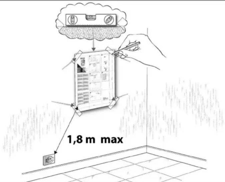
Observe the specifications indicated in this manual (figures 3, 4 and 5).
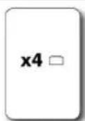
- Use the instructions sheet (supplied) as a template to mark the points where to make the holes for fixing (fig. 3).
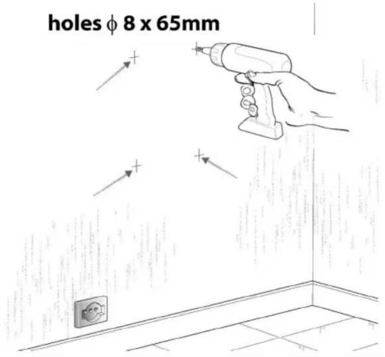
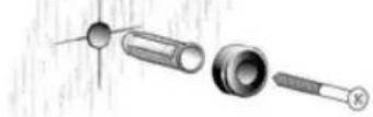
Remove and keep the sheet for future consultation and/or reuse. - With an 8 mm bit, drill four holes in the wall (fig. 4), and insert the expansion plugs (fig. 5).
- Insert the screws, taking care to previously insert the rubber spacers (fig. 5).
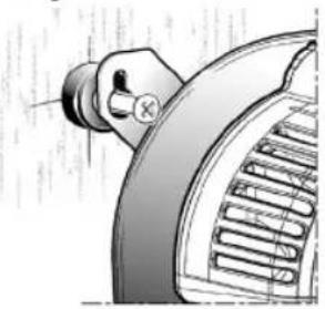
- Almost fully tighten the screws (fig. 6 - phase I).
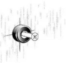
- Place the compressor in correspondence with the four screws, then hang it taking care to insert each slot of the compressor frame onto the screws: as shown in fig. 6 - phase II.
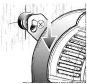
- Gently lower the compressor, so that all four screws can be inserted into the narrow shape of the slot, as shown in fig. 6 - phase III.
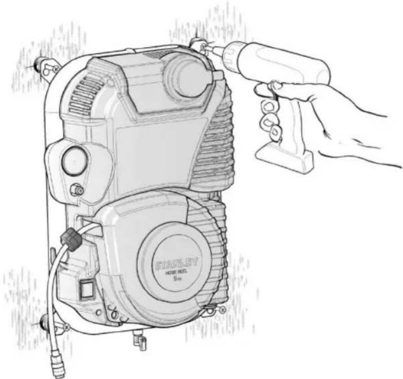
- Fully tighten the four screws (fig. 7).
7. SETTING
7.1 Connection to the network
The compressor is equipped with a power cord with shock-proof plug. Insert the plug of the power cord into a socket suitable regarding shape, voltage and frequency and compliant with current regulations. Before commissioning, make sure that the mains voltage corresponds to the operating voltage indicated on the data plate of the appliance. Make sure the ON/OFF switch is not in the I (ON) position.
Power cords that are too long as well as extensions, cable reels, etc. cause a voltage drop and can prevent the engine from starting. At low temperatures below +5°C, starting the engine can be more difficult.
7.2 Start-up and use
- Check the compliance of the compressor plate data with the real data of the electrical system; a voltage variation of ± 10% with respect to the nominal value is admitted.
- Connect the desired pneumatic tool to the quick coupling (ref. 5).
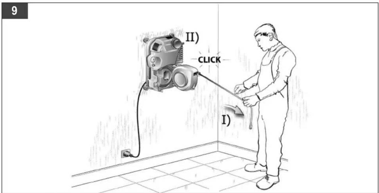
- The reel (ref. 7) is built with an automatic locking mechanism that allows the hose (ref. 4) to be stopped at the desired length.
Never let the hose rewind in an uncontrolled way.
– The locking system produces a metallic sound during unwinding and winding; it is not a sign of a defect.
If the noise changes after numerous applications and/or in case of problems with the mechanism, contact the service centre.
- Unwinding the hose: carefully remove the hose from the housing; after unwinding the necessary length of hose, loosen the grip slightly, in this way, when a "CLICK" is heard, the lock is inserted (fig. 9). Ensure that the hose is locked before releasing the grip.
- Rewinding the hose: loosen the lock by pulling the extension hose outwards (fig. 10). Let the hose rewind in a controlled way, accompanying it until it completely returns to the reel.
- Insert the power cord plug into a suitable socket, making sure that the I/O switch on the compressor is in the switched off position "O" (OFF).
- At this point the compressor is ready for use.
- Use the I/O switch to start the compressor pumping air and putting it through the delivery hose into the tank.
- Once the upper calibration value has been reached (set by the manufacturer during the test phase) the compressor stops.
Using air, the compressor restarts automatically when lower calibration value is reached (2 bar between upper and lower value).
- The compressor continues to operate with this cycle automatically until acting on the I/O switch.
- If the compressor shall be used again, wait at least 10 seconds from the moment when it switches off before restarting it.
- Check that the air consumption and the maximum operating pressure of the pneumatic tool to be used are compatible with the pressure set on the pressure regulator (not included) and with the amount of air delivered by the compressor.
- At the end of the work:
– rewind the hose completely, putting it in its housing;
- stop the compressor by acting on the I/O switch, putting it to the switched off position "O" (OFF).
– disconnect the electrical plug;
– empty the tank.
8. CLEANING AND MAINTENANCE
Warning!
Pull the power plug before doing any cleaning and maintenance work on the appliance.
Warning!
Wait until the compressor has completely cooled down. Risk of burns!
Warning!
Always depressurize the tank before carrying out any cleaning and maintenance work.
8.1 Cleaning
- Keep the safety devices free of dirt and dust as far as possible. Wipe the equipment with a clean cloth or blow it with compressed air at low pressure.
- We recommend that you clean the appliance immediately after you use it.
the. Do not use cleaning agents or solvents; these may be aggressive to the plastic parts in the appliance. Ensure that no water can get into the interior of the appliance.
- You must disconnect any pneumatic tools from the compressor before cleaning. Do not clean the compressor with water, solvents or the like.
- Keep the reel hose clean to allow proper sliding.
8.2 Condensation water (Fig. 11)
The condensation water must be drained off each day by opening the drain valve (ref. 3) (on the bottom of the pressure vessel).
Warning!
Dispose of the condensation water in an environmentally compatible manner at the appropriate collection point.
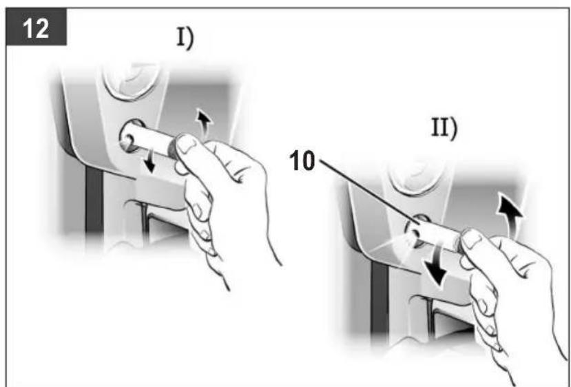
8.3 Safety valve (ref. 10)
The safety valve has been set for the highest permitted pressure of the pressure vessel.
It is prohibited to adjust the safety valve. Actuate the safety valve from time to time to ensure that it works when required. Turn the nut until you can hear the compressed air being released (Fig. 12). Then screw it back on.
Always keep the safety valve and the surrounding area clean and free of obstructions.
Always keep the safety valve and the surrounding area clean and free of obstructions.
| MAINTENANCE RESUMPTIVE TABLE | |||
| FUNCTION | AFTER THE FIRST 100 HOURS | EVERY 100 HOURS | |
| Cleaning of intake filter and/or substitution of filtering element | ● | ● | |
| Draining tank condensate | Daily and at the end of work | ||
8.4 Cleaning the intake filter (ref. 1)
The intake filter prevents dust and dirt being drawn in. It is essential to clean this filter after at least every 100 hours in service. A clogged intake filter will decrease the compressor's performance dramatically.
The body of the intake filter is irremovable, it MUST NEVER be removed. To clean or replace the filtering element, simply remove the cover. To remove the cover, unscrew counterclockwise.
Clean the filtering element by tapping it to remove the dirt, blast it down with low-pressure compressed air (approx. 3 bar) and re-insert it.
8.5 Storage

Warning!
Disconnect the plug from the socket, vent the appliance and tools connected to it and empty the condensate.
Switch off the compressor and make sure that it is secured in such a way that it cannot be started up again by any unauthorized person.

Warning!
Keep the compressor only in dry environment and not accessible to unauthorized persons.
Protect it with a cloth to prevent dust from settling on the internal mechanisms.
If the compressor remains inactive for long periods, check that it is working correctly before starting to use it again.
9. DISPOSAL AND RECYCLING
Pursuant to Directive 2012/19/EU on
waste electrical and electronic equipment (WEEE).
The symbol carrying a crossed-out refuse container depicted on any equipment or the relative packaging means that, at the end of its useful life, said product must be disposed of separately from other waste.
The user must therefore take said equipment to the centres specialising in differentiated refuse collection of electric and electronic equipment or alternatively return it to the reseller when purchasing a new similar piece of equipment.
Thanks to differentiated refuse collection, discarded equipment can be sent to be recycled, treated and disposed of in an environmentally-friendly manner; this helps avoiding possible negative effects on the environment and on health and promotes the re-employment and/or recycling of the equipment's materials.
Any unauthorised disposal of the product by the user will result in the application of the fines provided for by the regulations in force.
10. POSSIBLE FAULTS AND RELATED PERMITTED REMEDIES
| Fault Cause Remedy | ||
| The compressor stops and restarts automatically after a few minutes. | Tripping of the thermal cutout due to overheating of the motor. | Allow the compressor to cool down. Ventilate the work area. |
| After a few attempts to restart, the compressor stops. | Tripping of the thermal cutout due to overheating of the motor (removal of the plug with the compressor running, low power voltage). | Activate the I/O switch (On/Off). Ventilate the work area. Wait a few minutes. The compressor will restart independently. |
| The compressor does not stop and the safety valve is tripped. | Irregular compressor operation or pressure switch malfunction. | Remove the plug and contact the Service Center. |
Any other type of operation must be carried out by authorized Service Centers, requesting original parts. Tampering with the machine may impair its safety and in any case make the warranty null and void.
7. APPARATET SETTES I DRIFT
8.3 Sikkerhetsventil (ref. 10)
VEDLIKEHOLDSINTERVALLER
The Ground Truth image displays a single, solid horizontal line, which is a stylistic or background element (like a ruled paper line or separator), not a placeholder for text. According to Rule 2, such stylistic/background lines must be ignored by the OCR result. The OCR content provided is "", which consists of no characters. This correctly represents the absence of any textual content in the GT and correctly ignores it as a fill-in-the-blank placeholder. Since the GT contains no such placeholder and only a stylistic line, outputting nothing is correct. Therefore, the OCR result is consistent with the Ground Truth.
The Ground Truth image displays a single, solid horizontal line, which is a stylistic or background element (like a ruled paper line or separator), not a placeholder for text. According to Rule 2, such stylistic/background lines must be ignored by the OCR result. The OCR content provided is "", which consists of no characters. This correctly represents the absence of any textual content in the GT and correctly ignores it as a fill-in-the-blank placeholder. Since the GT contains no actual underscores and the OCR outputted nothing for this line, this complies with the rule that stylistic lines must be ignored. Therefore, the OCR result is consistent with the Ground Truth.
The Ground Truth image displays a single, solid horizontal line, which is a stylistic or background element (like a ruled paper line or separator), not a placeholder for text. According to Rule 2, such stylistic/background lines must be ignored by the OCR result. The OCR content provided is "", which consists of no characters. This correctly represents the absence of any textual content in the GT and correctly ignores it as a fill-in-the-blank placeholder. Since the GT contains no actual underscores and the OCR outputted nothing for this line, this complies with the “Stylistic/Background Lines (Ignore)” rule. Therefore, the OCR result is consistent with the Ground Truth.
5. ÜLESSEADMISJUHISED
Stanley® and the Stanley logo are registered trade marks of Stanley Black & Decker, Inc. or an affiliate thereof and are used under license.
Manufactured by:
FNA S.p.A. - Via Einaudi 6, Robassomero (TO) Italy.


- STANLEY
- FR Légende
- Preserve this handbook for future reference.
- PRECAUTIONS
- THINGS TO DO
- THINGS NOT TO DO
- THINGS YOU SHOULD KNOW
- DESCRIPTION OF THE APPLIANCE (Fig. 8)
- SCOPE OF USE
- PACKAGING CONTENTS LIST
- POINTS TO NOTE WHEN SETTING UP THE COMPRESSOR
- Attention!
- INSTALLATION
- Warning!
- Wall fixing
- SETTING
- Connection to the network
- Start-up and use
- Never let the hose rewind in an uncontrolled way.
- CLEANING AND MAINTENANCE
- Cleaning
- Condensation water (Fig. 11)
- Safety valve (ref. 10)
- Cleaning the intake filter (ref. 1)
- Storage
- DISPOSAL AND RECYCLING
- Pursuant to Directive 2012/19/EU on
- waste electrical and electronic equipment (WEEE).
- POSSIBLE FAULTS AND RELATED PERMITTED REMEDIES
- APPARATET SETTES I DRIFT
- Sikkerhetsventil (ref. 10)
- ÜLESSEADMISJUHISED
Brand : STANLEY
Model : FMXCMD152WE
Category : Compressor