
FineCoat 9700 - Paint spray WAGNER - Free user manual and instructions
Find the device manual for free FineCoat 9700 WAGNER in PDF.
| Product Type | HVLP paint sprayer (High Volume Low Pressure) |
| Brand | Wagner |
| Model | FineCoat 9700 |
| Category | Paint sprayer |
| Power consumption | 1150 W |
| Voltage | 230 V ~ 50 Hz |
| Max. electrical consumption | 5 A |
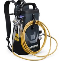
| Weight (turbine, hose, gun) | 6.8 kg |
| Air hose length | 7.6 m |
| Power cord length | 4 m |
| Standard nozzle set | No. 4 (1.8 mm) |
| Container capacity | 1000 ml |
| Sound pressure level | 80 dB(A) (uncertainty K=3 dB(A)) |
| Operating sound level | 91 dB(A) (uncertainty K=3 dB(A)) |
| Vibration level | < 2.5 m/s² (uncertainty K=1.5 m/s²) |
| Protection class | I |
| Max. product temperature | 43 °C |
| Spray technology | HVLP (high volume, low pressure) |
| Settings | Spray pattern (horizontal, vertical, round), material flow, air flow |
| Air filter | With clogging indicator (lights up red) |
| Maintenance | Regular cleaning of nozzle, air filter, ventilation valve |
| Included accessories | Spray gun, container, air hose, cleaning brushes, standard nozzle set |
| Warranty | 3 years + 2 additional years after registration (artisanal use) |
Frequently Asked Questions - FineCoat 9700 WAGNER
User questions about FineCoat 9700 WAGNER
0 question about this device. Answer the ones you know or ask your own.
Ask a new question about this device
Download the instructions for your Paint spray in PDF format for free! Find your manual FineCoat 9700 - WAGNER and take your electronic device back in hand. On this page are published all the documents necessary for the use of your device. FineCoat 9700 by WAGNER.
USER MANUAL FineCoat 9700 WAGNER
natural_image
Line drawing of a spray gun and a spray gun holder (no text or symbols)FINE COAT 9700

natural_image
Technical line drawing of a mechanical instrument with no visible text or symbols


natural_image
Mechanical assembly diagram showing a wheel and belt drive mechanism (no text or symbols)
natural_image
Technical line drawing of a mechanical device with no visible text or symbols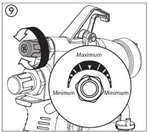
natural_image
Technical line drawing of a spray gun assembly (no text or symbols)
natural_image
Technical line drawing of a spray gun and spray gun assembly (no text or symbols)
natural_image
Line drawing of a mechanical device with a black arrow pointing to a component (no text or symbols)

natural_image
Technical line drawing of a mechanical device with spring and connecting rod components (no text or symbols)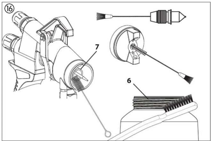

natural_image
Technical line drawing of a mechanical assembly with no visible text or symbols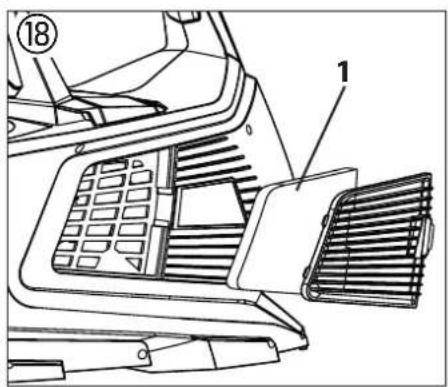


②2

Inhaltsverzeichnis
go.wagner-group.com/profi
PRÜFUNG DES GERÄTES
https://go.wagner-group.com/pf-warranty-conditions

Translation of the original operating instructions
Contents
1 SAFETY REGULATIONS 13
2 EXPLANATORY DIAGRAM 15
3 CHOOSING THE SPRAY NOZZLE SET 15
3.1 Swapping the spray nozzle set ____ 15
4 TECHNICAL DATA 16
5 INTRODUCTION TO SPRAYING USING THE HVLP PROCEDURE 16
6 COATING MATERIAL 16
6.1 Coating Materials Suitable for Use ____ 16
6.2 Coating Materials Not Suitable for Use ____ 16
6.3 Preparing the coating material 19
7 SETTING THE SPRAY GUN 17
7.1 Setting the required spray pattern ____ 17
7.2 Setting the amount of material 17
7.3 Setting the amount of air 17
7.4 Align the feed tube 17
12 TAKING OUT OF OPERATION AND CLEANING _ 18
12.1 Assembly 18
13 MAINTENANCE 19
13.1 Air filter 19
13.2 Air relief valve 19
13.3 Spray gun 19
14 CORRECTION OF MALFUNCTIONS 20
15 ACCESSORIES AND SPARE PARTS 21
15.1 Accessories 21
15.2 Spare parts FineCoat 9700 ____ 21
15.3 Spare Parts Ultra gun 21
Testing of the unit 22
Note on disposal 22
Important information on product liability ____ 22
Guarantee declaration 22
CE - declaration 22
European service network 118
Explanation of symbols used
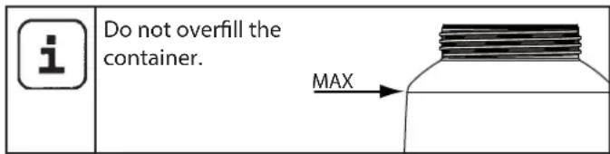
 | This symbol indicates a potential danger for you or for the device.Under this symbol you can find important information on how to avoid injuries and damage to the device. |
 | Indicates tips for use and other particularly useful information. |
1 SAFETY REGULATIONS
All local safety regulations in force must be observed.
Read the operating instructions carefully and follow the instructions laid down in them in order to avoid risks.
1. Safety at the workplace
a) Keep your workplace clean and well lit. Disorder or unlit workplaces may result in accidents.
b) Never use the tool in hazardous areas that contain flammable liquids, gases or dusts. Power tools generate sparks that can ignite the dust or vapors.
c) Keep children and other persons away when using the power tool. You can lose control of the tool if you are distracted.
2. Electrical Safety
a) The tool plug must fit into the socket. The plug may not be modified in any form. Do not use adaptor plugs together with protective-earthed tools. Unmodified plugs and suitable sockets reduce the risk of an electric shock.
b) Avoid physical contact with earthed surfaces such as pipes, heating elements, stoves and refrigerators. The risk through electric shock increases if your body is earthed.
c) Keep the equipment away from rain and moisture. The risk of an electric shock increases if water penetrates electrical equipment.
d) Do not misuse the mains lead by carrying the tool by the lead, hanging it from the lead or by pulling on the lead to remove the plug. Keep the lead away from heat, oil, sharp edges or moving tool parts. Damaged or twisted leads increase the risk of an electric shock.
e) If you work outdoors with a power tool, only use extension cables suitable for outdoor use. The use of an extension lead that is suitable for outdoors reduces the risk of an electric shock.
f)) If you cannot avoid using the tool in a damp environment, use a residual current operated circuit-breaker. Using a residual current operated circuit-breaker avoids the risk of electric shock.
3. Safety of Persons
a) Be attentive. Pay attention to what you are doing and work sensibly with a power tool. Do not use the tool if you are tired or under the influence of drugs, alcohol or medication. Just a moment of inattentiveness while using the tool can lead to serious injuries.
b) Wear personal safety equipment and always wear safety goggles. Wearing personal protective equipment, such as dust mask, non-slip safety shoes, safety helmet or ear protection, depending on the type of power tools, reduces the risk of injury.
c) Avoid accidental starting-up. Ensure that the switch is in the "OFF" position before inserting the plug into the socket. Accidents can occur if you carry the power tool while your finger is on the switch or if you connect the power tool to the power supply which it is on.
d) Remove setting tools or wrenches before switching on the power tool. A tool or wrench that is in a rotating tool part can lead to injuries.
e) Avoid an unnatural posture. This ensures that you can control the tool better in unexpected situations.
f) Wear suitable clothing. Do not wear wide clothing or jewellery. Keep your hair, clothes and gloves away from moving parts. Loose clothing, jewellery or long hair can be caught in moving parts.
g) Do not lull yourself into a false sense of security and do not think yourself above the safety rules for electric tools, even if you are familiar with the electric tool following extensive practical experience. Careless use can lead to serious injuries in fractions of a second.
4. Careful Handling and Use of Power Tools
a) Do not overload the tool. Use the power tool designed for the work that you are doing. You work better and safer in the specified performance range if you use the suitable power tool.
b) Do not use power tools whose switch is defective. A power tool that cannot be switched on or off is dangerous and has to be repaired.
c) Remove the plug from the socket before carrying out tool settings, changing accessories or putting the tool away. This precautionary measure prevents unintentional starting of the tool.
d) Store unused power tools so that they are inaccessible to children. Do not let persons use the tool who are not familiar with it or who have not read these instructions. Power tools are dangerous when they are used by inexperienced persons.
e) Take proper care of your tools. Check whether the moving parts function trouble-free and do not jam, whether parts are broken or damaged so that the tool function is impaired. Have damaged parts repaired before using the tool. Many accidents have their origin in power tools that have been maintained badly.
f) Use the power tool, accessories, insert tools, etc. in accordance with these instructions and in a fashion specified for this special tool type. Take the working conditions and the activity to be carried out into consideration. The use of power tools for purposes other than the intended ones can lead to dangerous situations.
g) Keep the handles and grip surfaces dry, clean and free of oil and grease. Slippery handles and grip surfaces hamper safe operation and control of the electric tool in unforeseen situations.
5. Service
a) Have your tool repaired only by qualified specialist
personnel and only with original spare parts. This ensures that the tool safety is maintained.
b) If the supply cord is damaged, it must be replaced by the manufacturer or its service agent or a similarly qualified person in order to avoid a safety hazard.
Safety instructions for colour application devices
- Risks of Fire and Explosion
Combustible gases develop in the work area when spraying coating substances and due to the autonomous formation of coating substances and solvent vapors (danger zone).
Risk of fire and explosion due to ignition sources in this danger zone.
The electrically operated spray device contains potential ignition sources (spark formation when switching the motor on and off, when inserting and removing the power plug, due to potential static electricity at the spray gun)
-> Device must not be used at operating sites that fall under the explosion protection ordinance.
-> Basic unit and mains connection must be located outside the danger zone.
-> Do not use combustible coating substances and cleaning agents -> observe product data sheets!
->Always seal paint or solvent containers tightly in the vicinity of the device.
-> No ignition sources such as open fire, lit tobacco products, glowing wires, hot surfaces, sparks e.g. due to angle grinders etc. must be present.
-> When cleaning the device with solvent do not spray into a container with a small opening (bung hole).
Danger due to formation of an explosive gas/air mixture.
The container into which you are spraying must be earthed.
- Warning: Danger of injury!
Never point spray gun at yourself, other persons or animals.
- Wear breathing equipment when spraying.
The user should be supplied with a breathing mask. In order to avoid occupational diseases, the working instructions provided by the manufacturer of the materials, solvents and cleaning agents used must be complied with during preparation, working with and cleaning the equipment. Protective clothing, gloves and, if necessary, protective skin cream is required to protect the skin.
- Warning: When working with the paint spraying system, both indoors and outdoors, care should
be taken that no solvent vapours are driven to the motor-operated blower or that no solvent containing vapours form in the area around the paint spraying system. Place the motor-operated blower on the opposite side to the object to be sprayed. When working outdoors take wind direction into account. When working in closed places a sufficient ventilation must be ensured to remove the solvent vapours. The distance from the motor – operated blower to the object to be sprayed must be at least 3 m.
-
Warning: The device is not splash proof. It should not be used, neither outdoors in the rain nor be sprayed with water nor immersed in liquid. Do not use the device in damp or wet environments.
-
The units may only be used with a functional valve. If paints rise in the ventilating hose (Fig. 1, item 4) do not operate the unit further! Dismantle and clean the ventilating hose, valve and diaphragm and replace the diaphragm if necessary (see section13.2).
-
Do not lay the filled spray gun down.
-
Extraction systems should be installed on-site according to the local regulations.
-
The object to be coated must be earthed.
-
Caution against dangers that can arise from the sprayed substance and observe the text and information on the containers or the specifications given by the substance manufacturer.
-
Do not spray any liquid of unknown hazard potential.
-
Before dismounting the spray attachment, relieve pressure by opening the container.
-
Before working on the device, remove the power plug from the socket.
-
Work or repairs on the electrical equipment should only be carried out by a professional electrician, even if there are instructions regarding such work in the operating instructions. No liability will be accepted for improper installation.
-
Do not sit or stand on the device. Danger of tilting/breaking!
-
Quick-release fasteners on the hose and spray gun become hot during use. Avoid skin contact with the quick-release fasteners if they are hot. Allow the quick-release fasteners to cool down before disconnecting the spray gun from the hose.
-
Only use parts approved by the manufacturer. The users bear all risks and liability for using parts that do not meet the minimum technical requirements.
2 EXPLANATORY DIAGRAM (FIG. 1)
POS. DESIGNATION
1 Spray gun complete
2 Spray jet width adjustment
3 Air cap (to set the working direction)
4 Ventilating hose
5 Valve
6 Container seal
7 Suction tube
8 Container
9 Trigger
10 Material volume regulation
11 Air volume control
12 Air hose
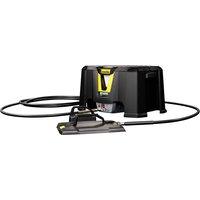
13 Carry handle
14 ON/OFF switch (I = ON, 0 = OFF)
POS. DESIGNATION
15 Air filter indicator ((lights up red if the main air filter is blocked))
16 Air hose connection
17 Storage compartment for small parts / accessories
18 Gun mounting
19 Clamp for securing the coiled power cable
20 Power cable
21 Air filter cover (left and right)
22 Fastening strap for binding the rolled-up air hose together
23 Coarse feed tube filter (white)
24 Cleaning brushes (4 pcs.)
3 CHOOSING THE SPRAY NOZZLE SET

Your HVLP paint spray gun must be equipped with the spray nozzle set appropriate for the work you are going to be carrying out. A spray nozzle set comprises a needle (1), a spray nozzle (2) and an air cap (3).

natural_image
Three technical diagrams of a mechanical component with labeled parts (no text or symbols present)You should choose your spray nozzle set based on two criteria: The type of material to be sprayed and the desired surface finish. Using the table on the following page, it will be easy for you to make the correct choice.
3.1 SWAPPING THE SPRAY NOZZLE SET
- Remove the regulator ring (Fig. 2, 4), the air cap (3) and the spring plate (5).
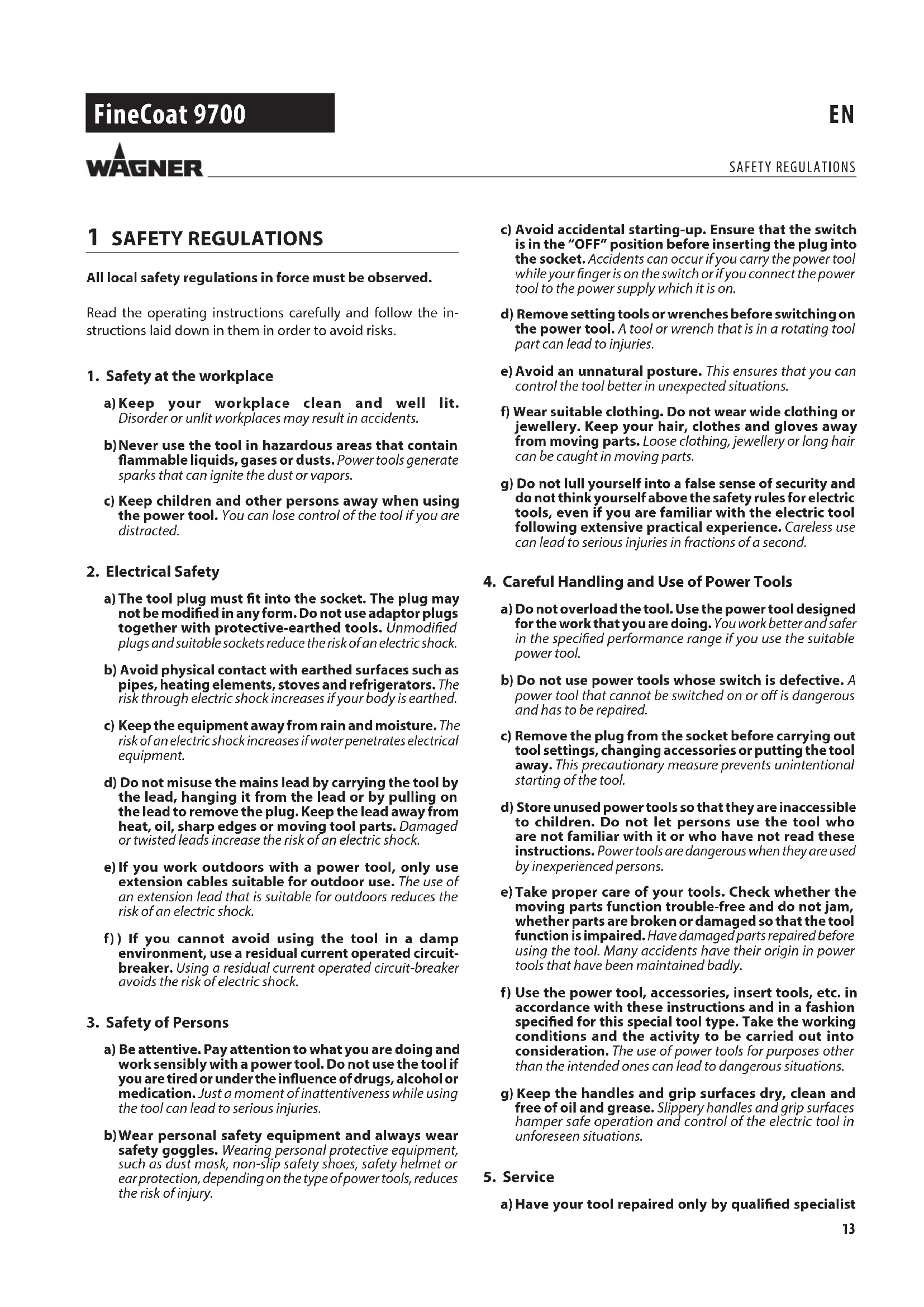
- Remove the spray nozzle. (Fig. 3)
- Remove the material regulator knob (Fig. 4, 6) and spring (7).
- Remove the needle (Fig. 5, 1).

If the needle does not slip out easily, loosen the nut (Fig. 5, 8) to avoid the needle or seal being damaged.
- The new spray nozzle set is assembled in the reverse order.
4 TECHNICAL DATA
| Voltage: 230 V~, 50 Hz | |
| Power consumption: 1150 W | |
| Max. current consumption 5 A | |
| Spray nozzle set (standard) No. 4 (1.8 mm) | |
| Container volume: 1000 ml | |
| Air hose: 7.6 m | |
| Power cable: 4 m | |
| Protection class: 43 °C | |
| Max. permitted temperature of the coating material | I |
| Sound pressure level:*Uncertainty K: | 80 dB (A)3 dB (A) |
| Sound pressure output:*Uncertainty K: | 91 dB (A)3 dB (A) |
| Oscillation level:Uncertainty K: | <2.5 m/s ^2 1.5 m/s ^2 |
| Weight (motor-operated blower, air hose and spray gun): 6.8 kg |
* The acoustic emission value was ascertained in accordance with EN 62841-1
5 INTRODUCTION TO SPRAYING USING THE HVLP PROCEDURE
HVLP (High Volume Low Pressure) is a low pressure spraying technique, which works with a high volume of air and a low air pressure. The greatest advantage of this spraying technique is the low paint mist formation. This reduces the amount required to cover the object to a minimum.
As opposed to conventional application of coatings, this method achieves a highly economical and perfect surface quality and is, at the same time, environmentally friendly.
Function description
The paint spraying system consists of a motor-operated turbo-blower, which provides the spray gun with atomisation air through an air hose.
In the spray gun, a part of the atomisation air is used to pressurise the container. This pressure causes the coating material to be fed through the uptake pipe to the nozzle where it is atomised by the rest of the atomisation air.
All settings necessary for operation (e.g. material volume) can be conveniently made, directly on the gun.
6 COATING MATERIAL
6.1 COATING MATERIALS SUITABLE FOR USE
Solvent-based and water-soluble lacquer paints Mordants, glazes, impregnations, oils, clear varnishes, synthetic enamels, coloured paints, alkyd resin varnishes, primers, radiator paints, hammer effect enamels, anti-rust paints, special-effect paints, textured paints
6.2 COATING MATERIALS NOT SUITABLE FOR USE
Materials that contain highly abrasive components, facade paint, caustic solutions and acidic coating substances.
Flammable materials.
6.3 PREPARING THE COATING MATERIAL

Observe the manufacturer's instructions for the use of the coating material on the paint tin or on the technical instruction sheet.
Coating material purity:
An absolute pre-condition for the trouble-free operation of the fine-spray system is that the coating material is uncontaminated. If you have doubts as to the purity of the coating material, we recommend that you first filter it through a fine sieve.
MATERIAL DILUTION / SPRAY NOZZLE SET TABLE
| COATING MATERIAL | VISCOSITY DIN-S* | SPRAY NOZZLE SET |
| Mordants, glazes, impregnations, oils | undiluted | 2 - 3(0.8 mm - 1.3 mm) |
| Solvent-based lacquer paints | 15 - 45 | 3 - 4(1.3 mm 1.8 mm) |
| Water-soluble lacquer paints | observe manufac-turer's instructions | 4 - 5(1.8 mm- 2.2 mm) |
| Textured and effect lacquers | observe manufac-turer's instructions | 5 - 6(2.2 mm - 2.5 mm) |
| Colourful effect materials, multi-colour paints | observe manufac-turer's instructions | 6 - 7(2.5 mm - 2.7 mm) |
* Use a viscosity cup (P/N 50342). Dip the viscosity test cup completely into the coating material. Hold the test cup up and measure the time in seconds until the liquid empties out.
7 SETTING THE SPRAY GUN
7.1 SETTING THE REQUIRED SPRAY PATTERN (FIG. 6)

Attention: Never pull trigger while adjusting the air cap settings.
Turn the air cap (Fig. 6, 3) to the desired spray pattern position.
A horizontal flat jet
for vertical surfaces
B vertical flat jet
for horizontal surfaces
C round jet
for corners and edges as well as hard-to-reach places.
The regulator ring can also be used to adjust the width of the spray jet (Fig. 7):
Turn to the right Wider spray jet
Turn to the left → Narrower spray jet
7.2 SETTING THE AMOUNT OF MATERIAL (FIG. 8)
Define the amount of material by turning the material regulator knob.
Turn to the left → More material
Turn to the right Less material
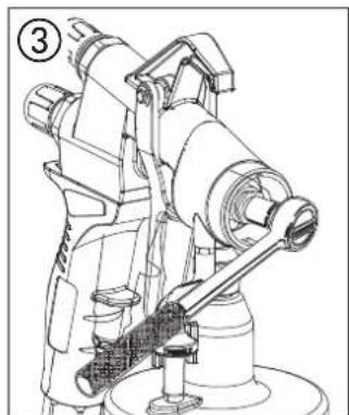
7.3 SETTING THE AMOUNT OF AIR (FIG. 9)
Turning the air volume regulator allows you to increase or reduce the amount of air.

The correct setting of air and material volume is crucial for atomisation and paint mist formation.
7.4 ALIGN THE FEED TUBE
If the feed tube is positioned correctly, the container contents can be sprayed without almost any residue.
When working on lying objects:
Turn the feed tube forwards. (Fig. 10 A)
Spraying work when working on overhead objects:
Turn the feed tube rearwards. (Fig. 10 B)
Before connecting to the mains supply make sure that the mains voltage corresponds to the operating voltage on the rating plate. The unit must be connected with a properly earthed shockproof socket.
- Attach the air hose to the gun using the quick-release fastener.
- Screw the other end of the hose to the base unit. (Fig. 11)
- Unscrew the container from the gun.
- Pour in the prepared coating material.
- Fit the filter to the feed tube (Fig. 12, 1)
- Screw the container firmly to the gun.
- Plug in the power cable.
- Switch on the main switch at the device.
The device is now ready for operation.
9 SPRAYING TECHNIQUE
Operate trigger on the spray gun.
Test spray a piece of cardboard to ensure correct setting of the spray pattern, spray jet width, material and air volume.
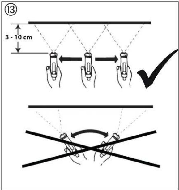
Hold the paint spray gun upright and maintain a constant distance of about 3 - 10 cm to the object being sprayed. (Fig. 13)
Move the paint spray gun evenly either from side to side or up and down. If the gun is moved evenly, it will produce an even surface finish.
Always start spraying away from the object and avoid stop-ping spraying whilst still on the object.
In case of excessive paint mist formation, adjust the air and material flow respectively and alter the distance from the object.
10 BREAKS IN WORK
- Turn the material regulator knob all the way to the right. The paint spray gun is then secured against accidental activation.
- Switch device off with main switch on the basic unit.
- Insert spray gun into gun mounting on the device.

In using quick-drying or two-component coating materials, do not fail to rinse unit through with a suitable cleaning agent during the processing period.
Important: The application life of the material can change as a result of heating. Therefore, please consult the material manufacturer.
11 TRANSPORTATION
- Coil power cable around the basic unit.
- Insert spray gun into gun mounting on the device.
- Unscrew the air hose from the base unit.
- Roll up the air hose and tie it up with the fastening strap.
12 TAKING OUT OF OPERATION AND CLEANING
- Turn the machine off.
- Unscrew the container.
Empty the remaining coating material into the original container. - Unscrew feed tube with container seal. (Fig. 14)

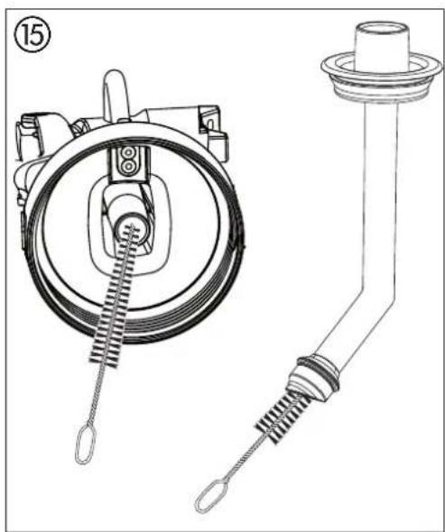
The enclosed brush set can be used for particularly effective cleaning of the spray attachment (examples Fig. 15 and 16).
- Clean the suction tube and intake support with a cleaning brush. (Fig. 15)
- Clean the ventilating bore. (Fig. 14, 2)

CAUTION! Never clean seals, diaphragm and nozzle or air holes of the spray gun with metal objects.
The ventilation hose and diaphragm are only solvent-resistant to a limited extent. Do not immerse in solvent, only wipe.
- Unscrew the regulator ring (Fig. 2, 4) and remove the air cap (3) and spring plate (5).
- Unscrew the nozzle. (Fig. 3)
- Clean the air cap, nozzle and needle with a brush and solvent or water. (Fig. 16)

Take special care when cleaning the interstices on the needle (Fig. 16, 7)
- Clean the outside of the spray gun and container with a cloth soaked in solvent or water. Use the all-purpose brush for the thread (Fig. 16, 6).
- Lightly lubricate at the marked points with silicone-free oil (Fig. 17).
- Assemble the parts again (see "Assembly").
12.1 ASSEMBLY

ATTENTION! Follow the steps described below exactly for assembly. Otherwise the gun may be damaged.
- Insert the nozzle into the gun and tighten it.
- Insert the spring plate and air cap and screw the regulator ring to the gun.
- Screw the feed tube with the container seal into the body of the gun.

If the paint spray gun is not going to be used for a while, it should be preserved with silicone-free oil after cleaning.
13 MAINTENANCE
13.1 AIR FILTER

Attention! Never operate the device with the air filter soiled or missing, as dirt could be sucked up and affect the operation of the device.
The air filter indicator lights up red if the air filter needs to be changed.
- Unplug the power plug.
- Open the cover on the air filter compartment (left and right) (Fig. 18).
- Depending on the degree of soiling, clean (blow out) the air filter (Fig. 18, 1) or replace it.
13.2 AIR RELIEF VALVE

If paint has entered the ventilation hose, proceed as follows:
- Pull the ventilating hose (Fig. 19, 1) at the top from the gun body. Screw off the valve cover (2). Remove the diaphragm (3). Clean all the parts carefully.

CAUTION! The ventilation hose and diaphragm are only solvent-resistant to a limited extent. Do not immerse in solvent, only wipe.
- Place the diaphragm in the valve cover with the pin facing forward.
- Turn the body of the gun upside down and screw on the valve cover from underneath.
- Place the ventilating hose on the valve cover and on the nipple at the gun body.
13.3 SPRAY GUN

Information regarding maintenance can be found in the gun's operating instructions.
Warning
If the supply cord of this appliance is damaged, it must only be replaced by a repair shop appointed by the manufacturer, because special purpose tools are required.
The wires in this mains lead are coloured in accordance with the following code:
$$ \begin{array}{r l} \text { green / yellow } & = \text { earth } \ \text { blue } & = \text { neutral } \quad \text { brown } = \text { live } \end{array} $$
As the colours of the wires in the mains lead of this appliance may not correspond with the coloured markings identifying the terminals in your plug, proceed as follows:
- The wire which is coloured green and yellow must be connected to the terminal in the plug which is marked with the letter E or by the earth symbol or coloured green or green and yellow.
- The wire which is coloured blue must be connected to the terminal which is marked with the letter N or coloured black.
- The wire which is coloured brown must be connected to the terminal which is marked with the letter L or coloured brown.
- Should the moulded plug have to be replaced, never re-use the defective plug or attempt to plug it into a different 13 A socket. This could result in an electric shock.
- Should it be necessary to exchange the fuse in the plug only use fuses approved by ASTA in accordance with BS 1362. Only 13 Amp fuses may be used.
- To ensure that the fuse and fuse carrier are correctly mounted please observe the provided markings or colour coding in the plug.
- After changing the fuse, always make sure that the fuse carrier is correctly inserted. With out the fuse carrier, it is not permissible to use the plug.
- The correct fuses and fuse carriers are available from your local electrical supplies stockist.

14 CORRECTION OF MALFUNCTIONS
| MALFUNCTION CAUSE REMEDY | ||
| The unit will not start | No mains voltageDevice overheated | CheckUnplug the power plug, let the device cool down approx. 30 minutes, do not bend the hose, check the air filter, do not cover the intake slots |
| No coating material emerges from the nozzle | Nozzle cloggedMaterial volume setting too lowPaint container seal damagedNo pressure build-up in containerContainer emptyVentilation hose loose/damagedFeed tube looseFeed tube / feed tube filter cloggedAir vent on feed tube blockedDiaphragm stuck | CleanIncrease volumeReplaceTighten containerRefillInsert or replaceInsertCleanCleanRemove and clean (see section 13.2) |
| Coating material drips from the nozzle | Air cap, nozzle or needle soiledNozzle wornNeedle worn or damaged | CleanChangeReplace the needle (see section 3.1) |
| Atomisation too coarse | Material volume too largeNozzle contaminatedViscosity of coating material too highToo little pressure build-up in containerAir filter heavily soiledAmount of air too lowAir hose damaged | Reduce volumeCleanDilute furtherTighten containerChange (see section 13.1)Increase volumeCheck and replace if necessary |
| Spray jet pulsates | Coating material in container running outAir filter heavily soiledFeed tube looseFeed tube / feed tube filter clogged | RefillChange (see section 13.1)InsertClean |
| Coating material causes “paint tears | Too much coating material appliedDistance too smallIncorrect spray nozzle set | Reduce volumeIncrease distanceUse a different spray nozzle set |
| Excessive paint mist (overspray) | Distance to the object too largeToo much coating material appliedAmount of air too highCoating substance over-dilutedIncorrect spray nozzle set | Reduce distanceReduce volumeReduce volumeReduce degree of dilutionUse a different spray nozzle set |
| Paint in the ventilating hose | Diaphragm soiledDiaphragm defective | Clean the diaphragm (see section 13.2)Replace the diaphragm (see section 13.2) |
15 ACCESSORIES AND SPARE PARTS
15.1 ACCESSORIES (FIG. 20)
POS. ORDER NO. DESIGNATION
1 0261 020 RN 30 EXTENSION NOZZLE for radiator coating, length 30 cm.
2 0261 023 WSL 50 SPRAY LANCE for renovation and repair work, ceiling and wall design. Material supply via conventional pressure tank
3 524232 Pressure container (2 l)
4 0261 024 WSL 60 SPRAY LANCE for coating materials that cannot be processed using a paint spray gun due to their properties, such as: liquid raw fibres, multi-colour effect coatings, stucco, structured and spray putties, etc.
5 2434549 Spray nozzle set, #2 (0.8 mm) cpl.
2434550 Spray nozzle set, #3 (1.3 mm) cpl.
2434551 Spray nozzle set, #4 (1.8 mm) cpl.
2434552 Spray nozzle set, #5 (2.2 mm) cpl.
2434553 Spray nozzle set, #6 (2.5 mm) cpl.
2434554 Spray nozzle set, #7 (2.7 mm) cpl.
15.2 SPARE PARTS FINECOAT 9700 (FIG. 21)
POS. ORDER NO. DESIGNATION
1 2434503 Filter cover set
2 2434505 Air filter (4 pcs.)
3 2434506 Storage compartment cover
4 2442013 Air hose
5 2430409 Cleaning brush set
6 2324 751 Air hose fixing strap
15.3 SPARE PARTS ULTRA GUN (FIG. 22)
POS. ORDER NO. DESIGNATION
1 2434391 Service Set front part
2 2434393 Service Set air valve
3 2434390 Service Set HVLP gun
4 2441860 Service Set air regulation
5 2434392 Service Seat seals (3 pcs.)
6 2434389 Service Set trigger guard
7 2434388 Service Set check valve
8 2434387 Intake cover
9 2434386 Suction system service set
10 2434385 Container seal (5 pcs.)
11 2434394 Container 1000 ml
12 2441862 Membrane (5 pcs.)
TESTING OF THE UNIT
For safety reasons, we would recommend having the device checked by an expert as required but at least every 12 months to ensure that it can continue to operate safely.
In the case of unused devices, the check can be postponed until they are next started up.
All (potentially deviating) national inspection and maintenance regulations must also be observed.
If you have any questions, please contact the customer service team at Wagner.
IMPORTANT INFORMATION ON PRODUCT LIABILITY
An EU directive valid since 01.01.1990 specifies that the manufacturer is only liable for his products if all the parts originate from the manufactured or are approved by him, and if the units are mounted and operated properly.
If accessories or spare parts from third parties are used, liability can be partially or completely inapplicable. In extreme cases the responsible authorities can prohibit the use of the entire unit (German industrial employer's liability insurance association and factory inspectorate).
With original WAGNER accessories and spare parts, compliance with all safety regulations is guaranteed.
NOTE ON DISPOSAL
In observance of the European Directive 2012/19/EU on waste electrical and electronic equipment and implementation in accordance with national law, this product is not to be disposed of together with household waste material but must be recycled in an environmentally friendly way!

Wagner or one of our dealers will take back your used Wagner waste electrical or electronic equipment and will dispose of it for you in an environmentally friendly way. Please ask your local Wagner service centre or dealer for details or contact us direct.
EU Declaration of conformity
We declare under sole responsibility that this product conforms to the following relevant stipulations:
2006/42/EC, 2014/30/EU, 2011/65/EU, 2012/19/EU
Applied harmonised norms:
EN 62841-1, EN 50580, EN IEC 55014-1, EN IEC 55014-2, EN IEC 61000-3-2, EN 61000-3-3, EN 62233
The EU declaration of conformity is enclosed with the product.
If required, it can be re-ordered using order number 2434455.
3 + 2 YEAR GUARANTEE ON THIS WAGNER CONTRACTOR PRODUCT
(Status 03.03.2022)
WAGNER exclusively provides the commercial buyer who has purchased the product from an authorised specialist dealer (hereinafter referred to as the „Customer“) with a guarantee for the products listed on the Internet at https://go.wagner-group.com/3plus2-info in addition to the statutory warranty regulations, unless there is a guarantee exclusion.
The guarantee period for WAGNER products (devices) in the contractor's sector is 36 months and begins with the date of purchase of the initial purchase. This guarantee period is extended by a further 24 months if the product is registered within 28 days of purchase on the Internet at https://go.wagner-group.com/3plus2.
In cases of commercial rental, industrial use (e.g. use in shift operation) or equivalent use, the guarantee period is 12 months due to the significantly higher load. We reserve the right to carry out a check in individual cases and refuse the guarantee where necessary.
If any material, machining or performance defects are identified in the device within the guarantee period, then the guarantee claims must be made immediately and within a period of no more than 2 weeks following discovery of the defect.
The detailed guarantee conditions can be obtained on request from our authorised WAGNER partners (see website or operating instructions) or in text form on our website:
https://go.wagner-group.com/pf-warranty-conditions

Subject to modifications
UKCA Declaration of conformity
We declare under sole responsibility that this product conforms to the following relevant regulations:
Supply of Machinery (Safety) Regulations 2018
Electromagnetic Compatibility Regulations 2016
The Restriction of the Use of Certain Hazardous Substances in Electrical and Electronic Equipment Regulations 2012
The Waste Electrical and Electronic Equipment Regulations 2013
Applied harmonised standards
BS EN 62841-1, BS EN 50580, BS EN IEC 55014-1,
BS EN IEC 55014-2, BS EN 61000-3-2, BS EN 61000-3-3,
BS EN 62233
6.1 PRODUITS DE REVÊTEMENT APPLICABLES
TABLEAU DILUTION PRODUIT / KIT GICLEUR
14 ELIMINATION DES DÉFAUTS
INDICATION DE MISE AU REBUT
https://go.wagner-group.com/pf-warranty-conditions
10 ARBEIDSONDERBREKING
https://go.wagner-group.com/pf-warranty-conditions

https://go.wagner-group.com/pf-warranty-conditions

15 ACCESSORI E RICAMBI 69
15.1 Accessori 69
15.2 Ricambi FineCoat 9700 69
15.3 Ricambi pistola Ultra 69
15 ACCESSORI E RICAMBI
15.1 ACCESSORI (FIG. 20)
POS. N° ORD. NOME
https://go.wagner-group.com/pf-warranty-conditions

15.2 Reservedele FineCoat 80
15.3 Reservedele pistol Ultra 80
2 BESKRIVELSE AF APPARATET (FIG. 1)
POS. BETEGNELSE
natural_image
Three technical line drawings of mechanical components: a rod, a threaded connector, and a flanged component (no text or symbols)https://go.wagner-group.com/pf-warranty-conditions

natural_image
Three technical line drawings of mechanical components: a rod, a conical connector, and a flanged component (no text or symbols)https://go.wagner-group.com/pf-warranty-conditions

https://go.wagner-group.com/pf-warranty-conditions

AUS Wagner Spraytech Australia Pty. Ltd. 8 – 10 Dansu Court Hallam, Victoria, 3803 Australia Customer Service 1800 924 637 info@wagneraustralia.com.au


- FINE COAT 9700
- Inhaltsverzeichnis
- PRÜFUNG DES GERÄTES
- Translation of the original operating instructions
- Contents
- Explanation of symbols used
- SAFETY REGULATIONS
- Safety at the workplace
- Electrical Safety
- Safety of Persons
- Careful Handling and Use of Power Tools
- Service
- Safety instructions for colour application devices
- EXPLANATORY DIAGRAM (FIG. 1)
- DESIGNATION
- CHOOSING THE SPRAY NOZZLE SET
- SWAPPING THE SPRAY NOZZLE SET
- TECHNICAL DATA
- INTRODUCTION TO SPRAYING USING THE HVLP PROCEDURE
- Function description
- COATING MATERIAL
- COATING MATERIALS SUITABLE FOR USE
- COATING MATERIALS NOT SUITABLE FOR USE
- PREPARING THE COATING MATERIAL
- Coating material purity:
- SETTING THE SPRAY GUN
- SETTING THE REQUIRED SPRAY PATTERN (FIG. 6)
- SETTING THE AMOUNT OF MATERIAL (FIG. 8)
- SETTING THE AMOUNT OF AIR (FIG. 9)
- ALIGN THE FEED TUBE
- SPRAYING TECHNIQUE
- BREAKS IN WORK
- TRANSPORTATION
- TAKING OUT OF OPERATION AND CLEANING
- ASSEMBLY
- MAINTENANCE
- AIR FILTER
- AIR RELIEF VALVE
- SPRAY GUN
- Warning
- ACCESSORIES AND SPARE PARTS
- ACCESSORIES (FIG. 20)
- SPARE PARTS FINECOAT 9700 (FIG. 21)
- SPARE PARTS ULTRA GUN (FIG. 22)
- TESTING OF THE UNIT
- IMPORTANT INFORMATION ON PRODUCT LIABILITY
- NOTE ON DISPOSAL
- EU Declaration of conformity
- + 2 YEAR GUARANTEE ON THIS WAGNER CONTRACTOR PRODUCT
- UKCA Declaration of conformity
- PRODUITS DE REVÊTEMENT APPLICABLES
- INDICATION DE MISE AU REBUT
- ARBEIDSONDERBREKING
- ACCESSORI E RICAMBI
- ACCESSORI (FIG. 20)
- BESKRIVELSE AF APPARATET (FIG. 1)
- BETEGNELSE
Brand : WAGNER
Model : FineCoat 9700
Category : Paint spray