
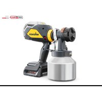
FinishControl 3500 Plus - Paint spray WAGNER - Free user manual and instructions
Find the device manual for free FinishControl 3500 Plus WAGNER in PDF.


| Product Type | XVLP Electric Spray Gun |
| Brand & Model | Wagner FinishControl 3500 Plus |
| Supply Voltage | 230 V ~ 50 Hz |
| Power Consumption | 700 W |
| Spray Power | 220 W |
| Container Capacity | 1000 ml (aluminium) |
| Power Cord Length | 4 m |
| Weight (turbine + gun) | 2.3 kg |
| Protection Class | I (grounded) |
| Sound Pressure Level | 74 dB(A) (uncertainty 4 dB(A)) |
| Sound Power Level | 87 dB(A) (uncertainty 4 dB(A)) |
| Vibration Level | < 2.5 m/s² (uncertainty 1.5 m/s²) |
| Spray System | XVLP (Extra Volume Low Pressure) |
| Available Adjustments | Spray pattern (vertical/horizontal), paint flow (1-12), air flow |
| Recommended Surfaces | Up to 50 m² per project |
| Compatible Paint Types | Solvent-based or water-based paints, stains, varnishes, primers (except abrasive or flammable products) |
| Maintenance and Cleaning | Clean the nozzle, air cap, and suction tube after each use; clean the air filter regularly |
| Spare Parts Available | Yes: removable fronts, nozzles, seals, filters, repair kits |
| Safety | Do not use in explosive atmospheres, wear a mask, do not direct the spray at people |
| Warranty | 3 years + 2 additional years after online registration |
Frequently Asked Questions - FinishControl 3500 Plus WAGNER
User questions about FinishControl 3500 Plus WAGNER
0 question about this device. Answer the ones you know or ask your own.
Ask a new question about this device
Download the instructions for your Paint spray in PDF format for free! Find your manual FinishControl 3500 Plus - WAGNER and take your electronic device back in hand. On this page are published all the documents necessary for the use of your device. FinishControl 3500 Plus by WAGNER.
USER MANUAL FinishControl 3500 Plus WAGNER
natural_image
Line drawing of a spray gun with attached cylindrical base (no text or symbols)FINISH CONTROL 3500 PLUS
natural_image
Technical line drawing of two mechanical components labeled A and B, showing assembly or assembly steps without any text or symbols.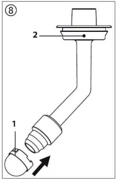
natural_image
Technical line drawing of a mechanical assembly with spring-loaded components (no text or symbols)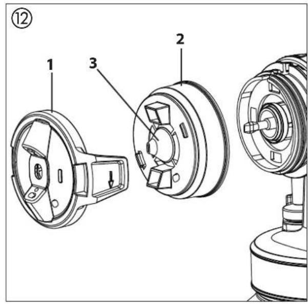
natural_image
Technical line drawing of a mechanical component with a magnified inset showing a circular feature and a black arrow pointing to a specific part (no text or symbols present)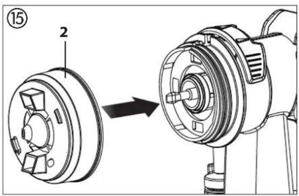
natural_image
Technical line drawing of a mechanical component with mounting brackets and warning symbols (no text or labels)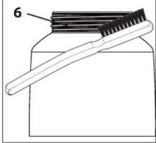
Inhaltsverzeichnis
natural_image
Technical line drawing of a mechanical component with a coiled spring and wheel (no text or symbols)natural_image
Technical line drawing of a car air intake manifold with control panel and fan (no text or symbols)natural_image
Pure mechanical cross-section diagram without any text, numbers, or symbolsnatural_image
Top-down view of a car dashboard with air vent and control panel (no text or symbols visible)go.wagner-group.com/profi
PRÜFUNG DES GERÄTES
https://go.wagner-group.com/pf-warranty-conditions

Translation of the original operating instructions
Contents
1 SAFETY REGULATIONS 14
2 EXPLANATORY DIAGRAM 16
3 THE WAGNER CLICK&PAINT SYSTEM 16
3.1 Disassembly of the spray gun 16
4 TECHNICAL DATA 17
5 INTRODUCTION TO SPRAYING USING THE XVLP PROCEDURE 17
6 COATING MATERIAL 17
6.1 Coating Materials Suitable for Use 17
6.2 Coating Materials Not Suitable for Use 17
6.3 Coating materials that can only be processed with relevant spray attachment (accessories) ____ 17
6.4 Preparing the coating material 17
7 SETTING THE SPRAY GUN 18
7.1 Setting the required spray pattern 18
7.2 Setting the amount of material 18
7.3 Setting the amount of air 18
7.4 Align the feed tube ____ 18
11 TAKING OUT OF OPERATION AND CLEANING _ 19
11.1 Assembly 20
12 MAINTENANCE 20
12.1 Air filter 20
12.2 Air relief valve 20
13 CORRECTION OF MALFUNCTIONS 21
14 ACCESSORIES AND SPARE PARTS 22
14.1 Accessories 22
14.2 Spare parts FinishControl 23
14.3 Spare Parts StandardSpray spray attachment ____ 23
Testing of the unit 24
Note on disposal 24
Important information on product liability ____ 24
Guarantee declaration 24
CE - declaration 24
European service network 122
Explanation of symbols used
 | This symbol indicates a potential danger for you or for the device.Under this symbol you can find important information on how to avoid injuries and damage to the device. |
 | Indicates tips for use and other particularly useful information. |
 | Wide spray jet setting |
 | Narrow spray jet setting |
1 SAFETY REGULATIONS
All local safety regulations in force must be observed.
Read the operating instructions carefully and follow the instructions laid down in them in order to avoid risks.
1. Work area safety
a) Keep work area clean and well lit. Cluttered or dark areas invite accidents.
b) Do not operate power tools in explosive atmospheres, such as in the presence of flammable liquids, gases or dust. Power tools create sparks which may ignite the dust or fumes.
c) Keep children and bystanders away while operating a power tool. Distractions can cause you to lose control.
2. Electrical safety
a) Power tool plugs must match the outlet. Never modify the plug in any way. Do not use any adapter plugs with earthed (grounded) power tools. Unmodified plugs and matching outlets will reduce risk of electric shock.
b) Avoid body contact with earthed or grounded surfaces, such as pipes, radiators, ranges and refrigerators. There is an increased risk of electric shock if your body is earthed or grounded.
c) Do not expose power tools to rain or wet conditions. Water entering a power tool will increase the risk of electric shock.
d) Do not abuse the cord. Never use the cord for carrying, pulling or unplugging the power tool. Keep cord away from heat, oil, sharp edges or moving parts. Damaged or entangled cords increase the risk of electric shock.
e) When operating a power tool outdoors, use an extension cord suitable for outdoor use. Use of a cord suitable for outdoor use reduces the risk of electric shock.
f) If operating a power tool in a damp location is unavoidable, use a residual current device (RCD) protected supply. Use of an RCD reduces the risk of electric shock.
3. Personal safety
a) Stay alert, watch what you are doing and use common sense when operating a power tool. Do not use a power tool while you are tired or under the influence of drugs, alcohol or medication. A moment of inattention while operating power tools may result in serious personal injury.
b) Use personal protective equipment. Always wear eye protection. Protective equipment such as a dust mask, non-skid safety shoes, hard hat or hearing protection used for appropriate conditions will reduce personal injuries.
c) Prevent unintentional starting. Ensure the switch is in the off-position before connecting to power source and/or battery pack, picking up or carrying the tool. Carrying power tools with your finger on the switch or energising power tools that have the switch on invites accidents.
d) Remove any adjusting key or wrench before turning the power tool on. A wrench or a key left attached to a rotating part of the power tool may result in personal injury.
e) Do not overreach. Keep proper footing and balance at all times. This enables better control of the power tool in unexpected situations.
f) Dress properly. Do not wear loose clothing or jewellery. Keep your hair and clothing away from moving parts. Loose clothes, jewellery or long hair can be caught in moving parts.
g) Do not let familiarity gained from frequent use of tools allow you to become complacent and ignore tool safety principles. A careless action can cause severe injury within a fraction of a second.
4. Power tool use and care
a) Do not force the power tool. Use the correct power tool for your application. The correct power tool will do the job better and safer at the rate for which it was designed.
b) Do not use the power tool if the switch does not turn it on and off. Any power tool that cannot be controlled with the switch is dangerous and must be repaired.
c) Disconnect the plug from the power source and/or remove the battery pack, if detachable, from the power tool before making any adjustments, changing accessories, or storing power tools. Such preventive safety measures reduce the risk of starting the power tool accidentally.
d) Store idle power tools out of the reach of children and do not allow persons unfamiliar with the power tool or these instructions to operate the power tool. Power tools are dangerous in the hands of untrained users.
e) Maintain power tools and accessories. Check for misalignment or binding of moving parts, breakage of parts and any other condition that may affect the power tool's operation. If damaged, have the power tool repaired before use. Many accidents are caused by poorly maintained power tools.
f) Use the power tool, accessories and tool bits etc. in accordance with these instructions, taking into account the working conditions and the work to be performed. Use of the power tool for operations different from those intended could result in a hazardous situation.
g) Keep handles and grasping surfaces dry, clean and
free from oil and grease. Slippery handles and grasping surfaces do not allow for safe handling and control of the tool in unexpected situations.
5. Service
a) Have your tool repaired only by qualified specialist personnel and only with original spare parts. This ensures that the tool safety is maintained.
b) If the supply cord is damaged, it must be replaced by the manufacturer or it's service agent or a similarly qualified person in order to avoid a safety hazard.
Safety instructions for colour application devices
1. Risks of Fire and Explosion
When spraying flammable coatings vapours from paint and solvents can cause flammable gases to be produced in the work area (hazard area).
Risk of fire and explosion due to ignition sources in this danger zone.
The electrically operated spray device contains potential ignition sources (spark formation when switching the motor on and off, when inserting and removing the power plug, due to potential static electricity at the spray gun)
-> Device must not be used at operating sites that fall under the explosion protection ordinance.
-> Do not use combustible coating substances and cleaning agents -> observe product data sheets!
->Always seal paint or solvent containers tightly in the vicinity of the device.
-> When cleaning devices with flammable solvents, disconnect the device from the mains and clean thoroughly with a brush and cloth. Before starting the device up again, ensure that all traces of solvents are removed thoroughly. Allow the cleaned parts to dry completely.
2. Warning: Danger of injury!
Never point spray gun at yourself, other persons or animals.
3. When spraying paint wear a suitable respirator.
The user should be supplied with a breathing mask. In order to avoid occupational diseases, the working instructions provided by the manufacturer of the materials, solvents and cleaning agents used must be complied with during preparation, working with and cleaning the equipment.
Protective clothing, gloves and, if necessary, protective skin cream is required to protect the skin.
- Warning: When working with the paint spraying system both indoors and outdoors, ensure that no solvent-based vapours can form within the area of the paint spraying system. When working in closed places a sufficient ventilation must be ensured to remove the solvent vapours.
- Warning: The device is not splash proof. It should not be used, neither outdoors in the rain nor be sprayed with water nor immersed in liquid. Do not use the device in damp or wet environments.
-
Attention! Never operate the device if the nozzle seal is missing, damaged or incorrectly mounted. If the nozzle seal is either missing, damaged or incorrectly mounted liquids can enter the device and increase the risk of an electric shock. Check the nozzle seal before each use.
-
The units may only be used with a functional valve. If paints rises in the ventilating hose (Fig. 1, item 13) do not operate the unit further! Dismantle and clean the ventilating hose, valve and diaphragm and replace the diaphragm if necessary.
- Do not lay the filled spray gun down.
- Extraction systems should be installed on-site according to the local regulations.
- The object to be coated must be earthed.
- Caution against dangers that can arise from the sprayed substance and observe the text and information on the containers or the specifications given by the substance manufacturer.
- Do not spray any liquid of unknown hazard potential.
- Before dismounting the spray attachment, relieve pressure by opening the container.
- Before working on the device, remove the power plug from the socket.
- Work or repairs on the electrical equipment should only be carried out by a professional electrician, even if there are instructions regarding such work in the operating instructions. No liability will be accepted for improper installation.

natural_image
Technical line drawing of a mechanical pulley system with a coiled spring (no text or symbols)2 EXPLANATORY DIAGRAM (FIG. 1)
POS. DESIGNATION
| 1 Air cap (to set the working direction) |
| 2 Spray jet width adjustment |
| 3 Material volume regulation |
| 4 Air filter cover lock |
| 5 Air filter cover |
| 6 Air volume control |
| 7 Power cable |
| 8 Trigger (actuates turbine starting switch → material is conveyed) |
| 9 Container |
| 10 Suction tube |
POS. DESIGNATION
| 11 Container seal |
| 12 Valve |
| 13 Ventilating hose |
| 14 Cleaning brushes (4 pcs.) |
| 15 Fine feed tube filter (red)Coarse feed tube filter (white) |
| 16 Carrying bag |
| 17 Velcro to secure the power cable |
3 THE WAGNER CLICK&PAINT SYSTEM
With the Wagner Click&Paint System, the front part of the gun (spray attachment) can be replaced quickly and easily.
This enables a rapid material change without cleaning, and ensures that the right tool is available for every material and application.
The following spray attachments are available:
| Spray attachment Area of application | |
| StandardSpray (yellow)Order No. 2430386 | Spray attachment with slit nozzle and 1000 ml aluminium container. Processes all standard paints. |
| FineSpray (brown)Order No. 2430385 | Spray attachment with round nozzle and 1000 ml aluminium container. Ideal for low-viscosity paints and glazes. |
| WallSpray (white)Order No. 2430387 | Dispersion spray attachment with slit nozzle and 1400 ml plastic container. Designed for processing dispersions. |
3.1 DISASSEMBLY OF THE SPRAY GUN
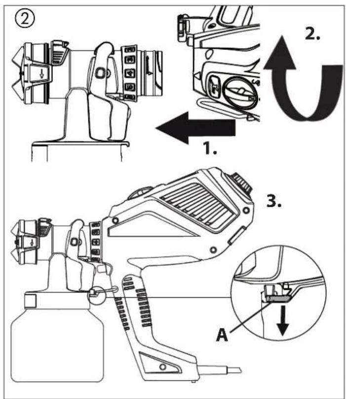
For assembly, insert the spray attachment into the FC 3500 so that the two arrows point at each other.
Turn the FC 3500 90° in the arrow direction until it audibly engages. (Fig. 2)
To remove the spray attachment, push the catch (Fig. 2, A) beneath the trigger down and turn the spray attachment by 90^ .
4 TECHNICAL DATA
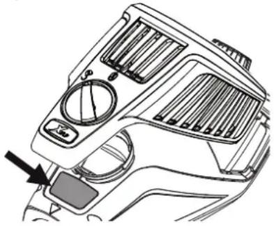
i
The rating plate is underneath the air filter cover.
natural_image
Technical line drawing of a car dashboard with air vent and control panel (no text or symbols)| Voltage: 230 V~, 50 Hz | |
| Power consumption: 700 W | |
| Atomizing output: 220 W | |
| Container volume: 1000 ml | |
| Power cable: 4 m | |
| Protection class: I | |
| Sound pressure level:*Uncertainty K: | 74 dB (A)4 dB (A) |
| Sound pressure output:*Uncertainty K: | 87 dB (A)4 dB (A) |
| Oscillation level:Uncertainty K: | <2.5 m/s^2 1.5 m/s^2 |
| Weight (motor-operated blower and spray gun): 2.3 kg |
* The acoustic emission value was ascertained in accordance with EN 62841-1
5 INTRODUCTION TO SPRAYING USING THE XVLP PROCEDURE
XVLP (Extra Volume Low Pressure) is a low pressure spraying technique, which works with a high volume of air and a low air pressure. The greatest advantage of this spraying technique is the low paint mist formation. This reduces the amount required to cover the object to a minimum.
As opposed to conventional application of coatings, this method achieves a highly economical and perfect surface quality and is, at the same time, environmentally friendly.
Function description
The paint spraying system consists of a motor-operated turbo-blower, which provides the spray gun with atomisation air. In the spray gun, a part of the atomisation air is used to pressurise the container. This pressure causes the coating material to be fed through the uptake pipe to the nozzle where it is
atomised by the rest of the atomisation air.
All settings necessary for operation (e.g. material volume) can be conveniently made, directly on the gun.
Field of application
The FC 3500 is designed for smaller to medium-sized projects, i.e. for surfaces of a maximum of 50 m^2 .
6 COATING MATERIAL
6.1 COATING MATERIALS SUITABLE FOR USE
Solvent-based and water-soluble lacquer paints
Mordants, glazes, impregnations, oils, clear varnishes, synthetic enamels, coloured paints, alkyd resin varnishes, primers, radiator paints, hammer effect enamels, anti-rust paints, special-effect paints, textured paints
6.2 COATING MATERIALS NOT SUITABLE FOR USE
Materials that contain highly abrasive components, facade paint, caustic solutions and acidic coating substances.
Flammable materials.
6.3 COATING MATERIALS THAT CAN ONLY BE PROCESSED WITH RELEVANT SPRAY ATTACHMENT (ACCESSORIES)
Interior wall paint (dispersions and latex paint)
6.4 PREPARING THE COATING MATERIAL

Observe the manufacturer's instructions for the use of the coating material on the paint tin or on the technical instruction sheet.
Coating material purity:
An absolute pre-condition for the trouble-free operation of the fine-spray system is that the coating material is uncontaminated. If you have doubts as to the purity of the coating material, we recommend that you first filter it through a fine sieve.
Processing the coating material with the StandardSpray spray attachment (yellow)
| Coating Material | Processing | Comments |
| Solvent-based lacquer paints | observe manufac-turer's instructions | |
| Water-soluble lacquer paints | observe manufac-turer's instructions | |
| Mordants, glazes, impregnations, oils | undiluted FineSpray | spray attachment (brown) recommended |
| Clear varnishes, synthetic enamels, coloured paints, alkyd resin varnishes | observe manufac-turer's instructions | |
| Primers, radiator paints, hammer effect enamels | observe manufac-turer's instructions | |
| Anti-rust paints, special-effect paints | observe manufac-turer's instructions | |
| Multicolor paints, textured paints | observe manufac-turer's instructions | WallSpray spray attachment (white) recommended |
7 SETTING THE SPRAY GUN
7.1 SETTING THE REQUIRED SPRAY PATTERN
| Attention:Never pull trigger while adjusting the air cap settings. |
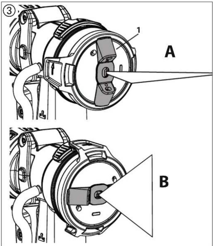
2 different spray jet shapes can be set by turning the air cap (fig. 3, 1)
| i | Only turn the air cap in the direction of the arrow, since otherwise the union nut can come loose. | 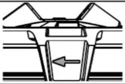 |
A horizontal flat jet
for vertical surfaces
B vertical flat jet
for horizontal surfaces
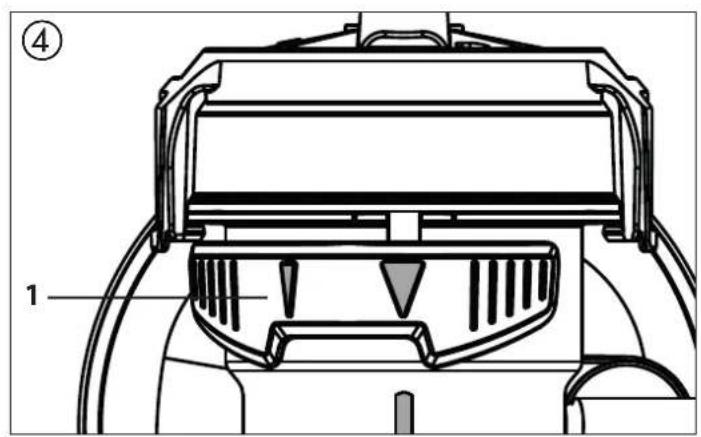
The controller (Fig. 4, 1) also allows the user to switch between a wide (and narrow () spray jet.
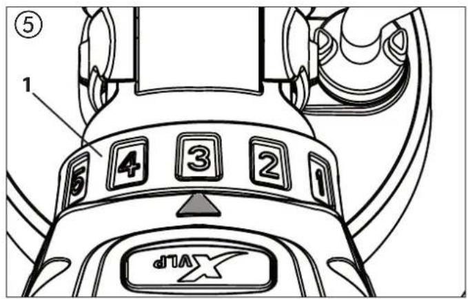
7.2 SETTING THE AMOUNT OF MATERIAL (FIG. 5)
The material volume can be adjusted incrementally from 1 (minimum) to 12 (maximum) by turning the material volume control (Fig. 5, 1).
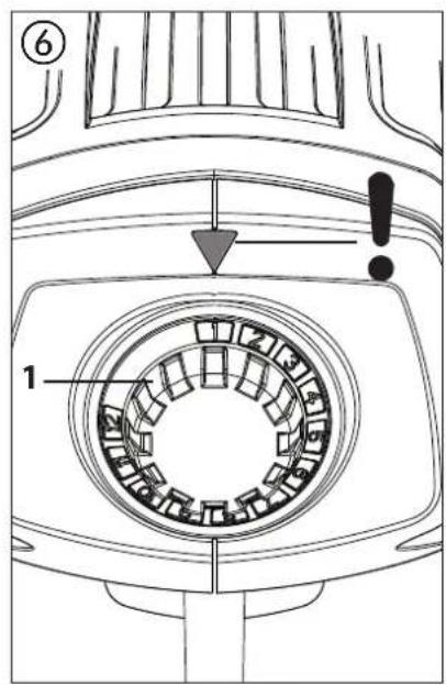
7.3 SETTING THE AMOUNT OF AIR (FIG. 6)
Turn the air volume control (Fig. 6, 1) clockwise to increase the air volume or anti-clockwise to reduce the air volume (note arrow on body of gun).

Setting the air and paint flow rate correctly is important for atomisation, overspray and working speed.
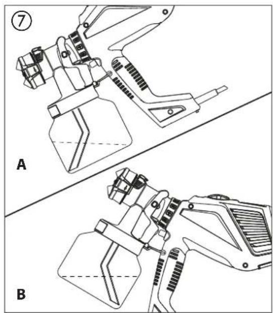
7.4 ALIGN THE FEED TUBE
If the feed tube is positioned correctly, the container contents can be sprayed without almost any residue.
When working on lying objects:
Turn the feed tube forwards. (Fig. 7 A)
Spraying work when working on overhead objects:
Turn the feed tube rearwards. (Fig. 7 B)
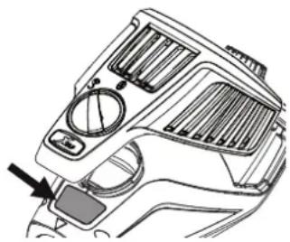
Before connecting to the mains supply make sure that the mains voltage corresponds to the operating voltage on the rating plate. The unit must be connected with a properly earthed shockproof socket.
natural_image
Technical diagram of a vehicle dashboard with no visible text or symbols- Unscrew the container from the spray attachment.
- Pour in the prepared coating material.

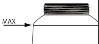
Do not overfill the container.
- Fit the appropriate filter to the feed tube depending on the coating material used (Fig. 8, 1)
Low-viscosity coating materials → Fine filter (red)
Viscous coating materials → Coarse filter (white)
- Align the feed tube. (Fig. 7)
- Screw the container firmly onto the spray attachment.
- Connect spray attachment and FC 3500. (Fig. 2)
- Plug in the power cable.
- The device is now ready for operation.
9 SPRAYING TECHNIQUE

The FC 3500 has a trigger with 2 pressure points. The turbine is started via the first pressure point. If the trigger is pressed further, the material is transported.
Operate trigger on the spray gun.
Test spray a piece of cardboard to ensure correct setting of the spray pattern, spray jet width, material and air volume.
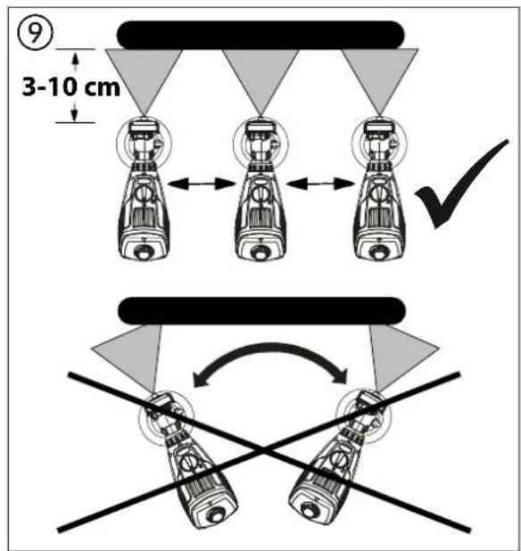
Hold the paint spray gun upright and maintain a constant distance of about 3 - 10 cm to the object being sprayed. (Fig. 9)
Move the paint spray gun evenly either from side to side or up and down. If the gun is moved evenly, it will produce an even surface finish.
Always start spraying away from the object and avoid stopping spraying whilst still on the object.
In case of excessive paint mist formation, adjust the air and material flow respectively and alter the distance from the object.
10 BREAKS IN WORK
- Unplug the power plug.
- During longer breaks, vent the container by briefly opening and then closing it again.
- Clean nozzle openings after an interruption in operation.

In using quick-drying or two-component coating materials, do not fail to rinse unit through with a suitable cleaning agent during the processing period.

ATTENTION! Full containers have to be closed tightly when transported in the bag. Do not lay the bag on its side if it contains filled containers.
11 TAKING OUT OF OPERATION AND CLEANING

In order to ensure smooth operations, the FC 3500 has to be cleaned thoroughly every day.
- Turn the machine off.
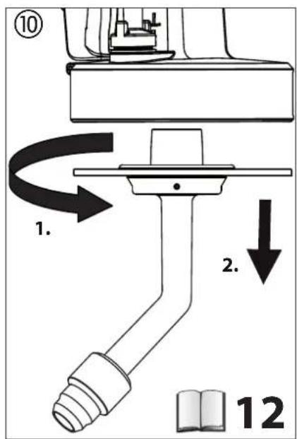
- Divide the spray gun. Press catch (Fig. 2, A) down slightly. Twist the spray attachment and turbine in a counter movement to disconnect them from each other.

ATTENTION! Never hold the spray gun rear part under water or immerse it into liquids. Clean the housing only with a moistened cloth.
- Unscrew the container.
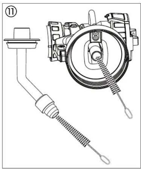
Empty the remaining coating material into the original container. - Clean feed tube and suction nozzle in spray attachment with cleaning brush. (Fig. 11)
- Clean the ventilating bore. (Fig. 8, 2)

When cleaning devices with flammable solvents, disconnect the device from the mains and clean thoroughly with a brush and cloth. Before starting the device up again, ensure that all traces of solvents are removed thoroughly. Allow the cleaned parts to dry completely.
- Move the air cap (Fig. 12, 1) to the vertical position for easier removal and lift it off.
- Unscrew the union nut (fig. 12, 2).
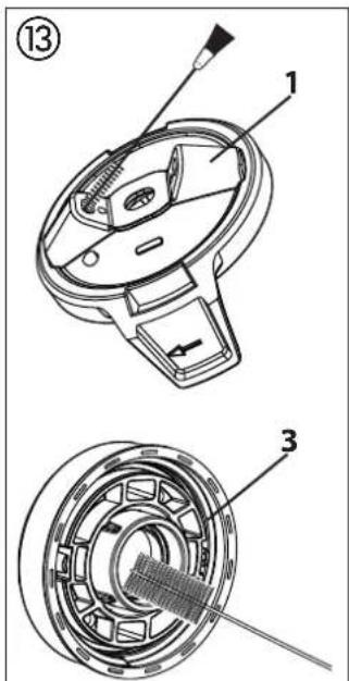
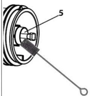
- Clean the air cap (fig. 13, 1) and nozzle (3) with a brush and solvent or water.

Take special care when cleaning the interstices on the needle (Fig. 13, 5)
-
Clean the outside of the container with a cloth soaked in solvent or water. Use the all-purpose brush for the thread (Fig. 13, 6).
-
Assemble the parts again (see "Assembly").
11.1 ASSEMBLY

ATTENTION! Follow the steps described below exactly for assembly. Otherwise the spray attachment may be damaged.

ATTENTION! Never operate the device if the nozzle seal is missing, damaged or incorrectly mounted. If the nozzle seal is either missing, damaged or incorrectly mounted liquids can enter the device and increase the risk of an electric shock.
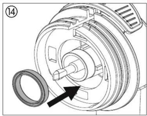
- Push nozzle seal onto the needle so that the groove (slot) points away from the spray attachment. (Fig. 14)
- Screw the union nut (Fig. 15, 2) onto the gun and tighten it.
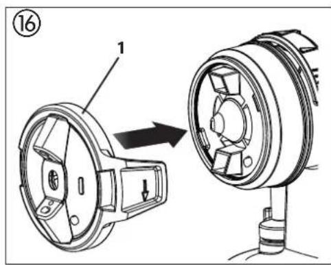
- Engage the air cap (Fig. 16, 1) with the union nut. Check if the air cap has properly locked into place on both sides.
- Place the container seal from below on the feed tube and slide it over the collar, while turning the container seal slightly.
- Screw the feed tube with the container seal into the body of the gun.

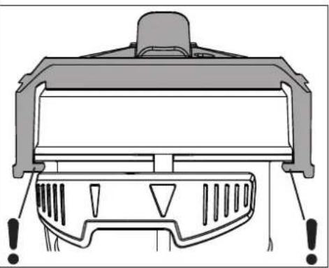
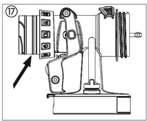
In order to mount the gun more easily apply lubricating grease (enclosed) liberally to the O-ring at the spray attachment (Fig. 17).
12 MAINTENANCE
12.1 AIR FILTER

Attention! Never operate the device with the air filter soiled or missing, as dirt could be sucked up and affect the operation of the device.
Always check the air filter before starting work.
- Unplug the power plug.
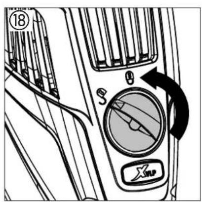
- Release the air filter compartment (Fig. 18) and remove.
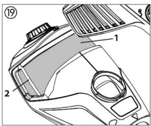
- Clean (blow out) or replace the air filter (Fig. 19,1) depending on the degree of soiling.
- Push the clean air filter underneath the fixtures (fig. 19, 2) on the left and right-hand sides (pay attention to the shape of the air filter and compartment).
- Reattach the cover of the air filter compartment and lock ⓝ.
12.2 AIR RELIEF VALVE

If paint has entered the ventilation hose, proceed as follows:
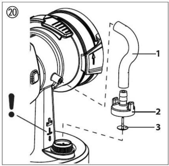
- Pull the ventilating hose (Fig. 20, 1) at the top from the gun body. Screw off the valve cover (2). Remove the diaphragm (3). Clean all the parts carefully.

CAUTION! The ventilation hose and diaphragm are only solvent-resistant to a limited extent. Do not immerse in solvent, only wipe.
- Place the diaphragm in the valve cover with the pin facing forward (Also see the marking on the gun body).
- Turn the body of the gun upside down and screw on the valve cover from underneath.
- Place the ventilating hose on the valve cover and on the nipple at the gun body.
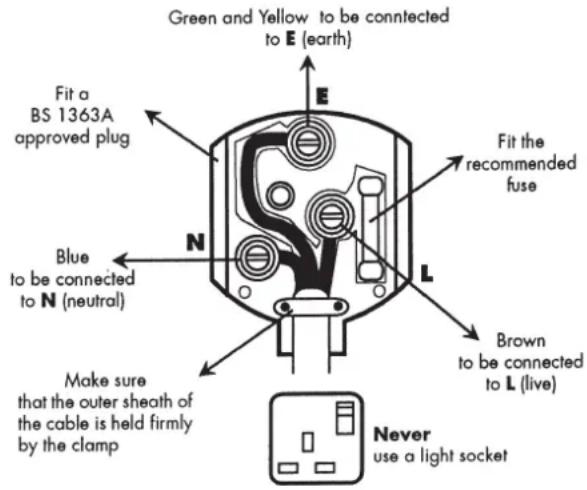
Warning
If the supply cord of this appliance is damaged, it must only be replaced by a repair shop appointed by the manufacturer, because special purpose tools are required.
The wires in this mains lead are coloured in accordance with the following code:
$$ \begin{array}{r l} \text { green / yellow } & = \text { earth } \ \text { blue } & = \text { neutral } \quad \text { brown } = \text { live } \end{array} $$
As the colours of the wires in the mains lead of this appliance may not correspond with the coloured markings identifying the terminals in your plug, proceed as follows:
- The wire which is coloured green and yellow must be connected to the terminal in the plug which is marked with the letter E or by the earth symbol or coloured green or green and yellow.
- The wire which is coloured blue must be connected to the terminal which is marked with the letter N or coloured black.
- The wire which is coloured brown must be connected to the terminal which is marked with the letter L or coloured brown.
-
Should the moulded plug have to be replaced, never re-use the defective plug or attempt to plug it into a different 13 A socket. This could result in an electric shock.
-
Should it be necessary to exchange the fuse in the plug only use fuses approved by ASTA in accordance with BS 1362. Only 13 Amp fuses may be used.
- To ensure that the fuse and fuse carrier are correctly mounted please observe the provided markings or colour coding in the plug.
- After changing the fuse, always make sure that the fuse carrier is correctly inserted. With out the fuse carrier, it is not permissible to use the plug.
- The correct fuses and fuse carriers are available from your local electrical supplies stockist.
13 CORRECTION OF MALFUNCTIONS
| MALFUNCTION CAUSE REMEDY | ||
| The unit will not start | No mains voltage | Check |
| No coating material emerges from the nozzle | Nozzle cloggedMaterial volume setting too lowPaint container seal damagedNo pressure build-up in containerContainer emptyVentilation hose loose/damagedFeed tube looseFeed tube / feed tube filter cloggedAir vent on feed tube blockedDiaphragm stuckThe diaphragm is positioned the wrong way round. | CleanIncrease volumeReplaceTighten containerRefillInsert or replaceInsertClean or use another filterCleanRemove and clean (see section 12.2)Position the diaphragm correctly (see section 12.2) |
| Coating material drips from the nozzle | Air cap, nozzle or needle soiledSpray attachment incorrectly assembledNozzle looseNozzle seal is missing or wornNozzle wornNeedle worn | CleanAssemble correctly (see section 11.1)Tighten Union nutInsert an intact nozzle sealChangeReplace the needle (service set 2434517) |
| Atomisation too coarse | Material volume too largeNozzle contaminatedViscosity of coating material too highToo little pressure build-up in containerAir filter heavily soiledAmount of air too lowAir cap assembled incorrectly | Reduce volumeCleanDilute furtherTighten containerChange (see section 12.1)Increase volumeSnap air cap properly into place (fig. 16) |
| Spray jet pulsates | Coating material in container running outNozzle seal is missing or wornAir filter heavily soiledFeed tube looseFeed tube / feed tube filter clogged | RefillInsert an intact nozzle sealChange (see section 12.1)InsertClean or use another filter |
| Coating material causes “paint tears | Too much coating material appliedDistance too smallIncorrect spray attachment | Reduce volumeIncrease distanceUse another spray attachment |
| Excessive paint mist (overspray) | Distance to the object too largeToo much coating material appliedAmount of air too highCoating substance over-dilutedIncorrect spray attachmentIncorrect spraying technique | Reduce distanceReduce volumeReduce volumeReduce degree of dilutionUse another spray attachmentFor information about the correct spraying technique, please see chapter 9 |
| Paint in the ventilating hose | Diaphragm soiledDiaphragm defective | Clean the diaphragm (see section 12.2)Replace the diaphragm (see section 12.2) |
14 ACCESSORIES AND SPARE PARTS
14.1 ACCESSORIES
POS. ORDER NO. DESIGNATION
1 2430 386 StandardSpray spray attachment (yellow) (with 1000 ml container) Processes all standard paints.
2 2430 385 FineSpray spray attachment (brown) (with 1000 ml container) Ideal for low-viscosity paints and glazes.
3 2430 387 WallSpray spray attachment (white) (with 1400 ml container) Designed for processing dispersions.
4 2324 749 Container with cover (1400 ml)
5 2350 692 Can Adapter
With the Can Adapter, paint cans can be attached directly to a Click&Paint spray attachment.
Suitable for: commercially available 750 ml paint tins (maximum dimensions =102 mm, h=119 mm) and 1000 ml paint tins (maximum dimensions =112 mm, h=132 mm).
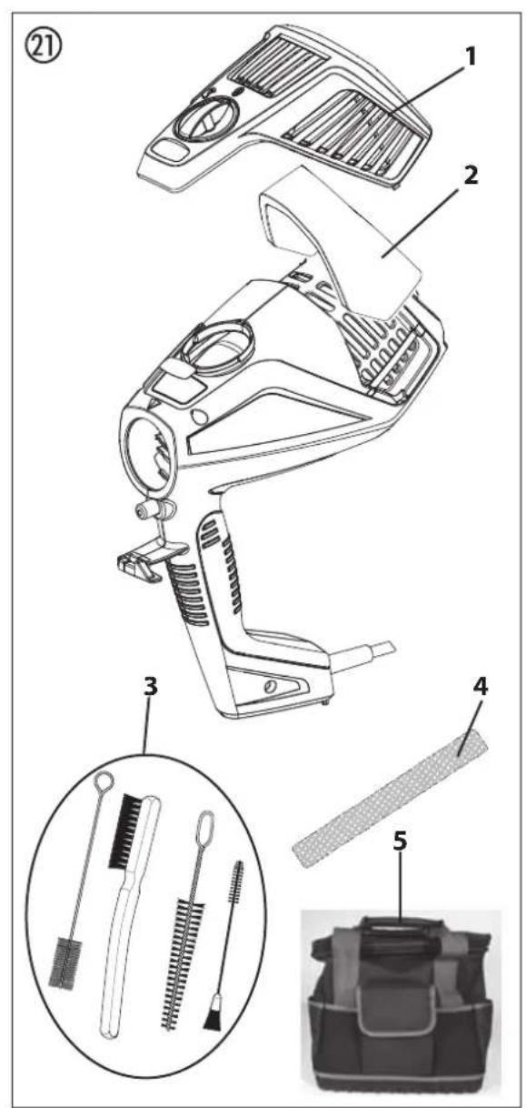
14.2 SPARE PARTS FINISHCONTROL 3500 (FIG. 21)
| POS. | ORDER NO. | DESIGNATION |
| 1 | 2343 946 Cover of air filter compartment | |
| 2 | 2343 947 Air filter (3 pcs.) | |
| 3 | 2430 409 Cleaning brush set | |
| 4 | 2344 041 | Velcro to secure the power cable |
| 5 | 2454 642 | Carrying bag |
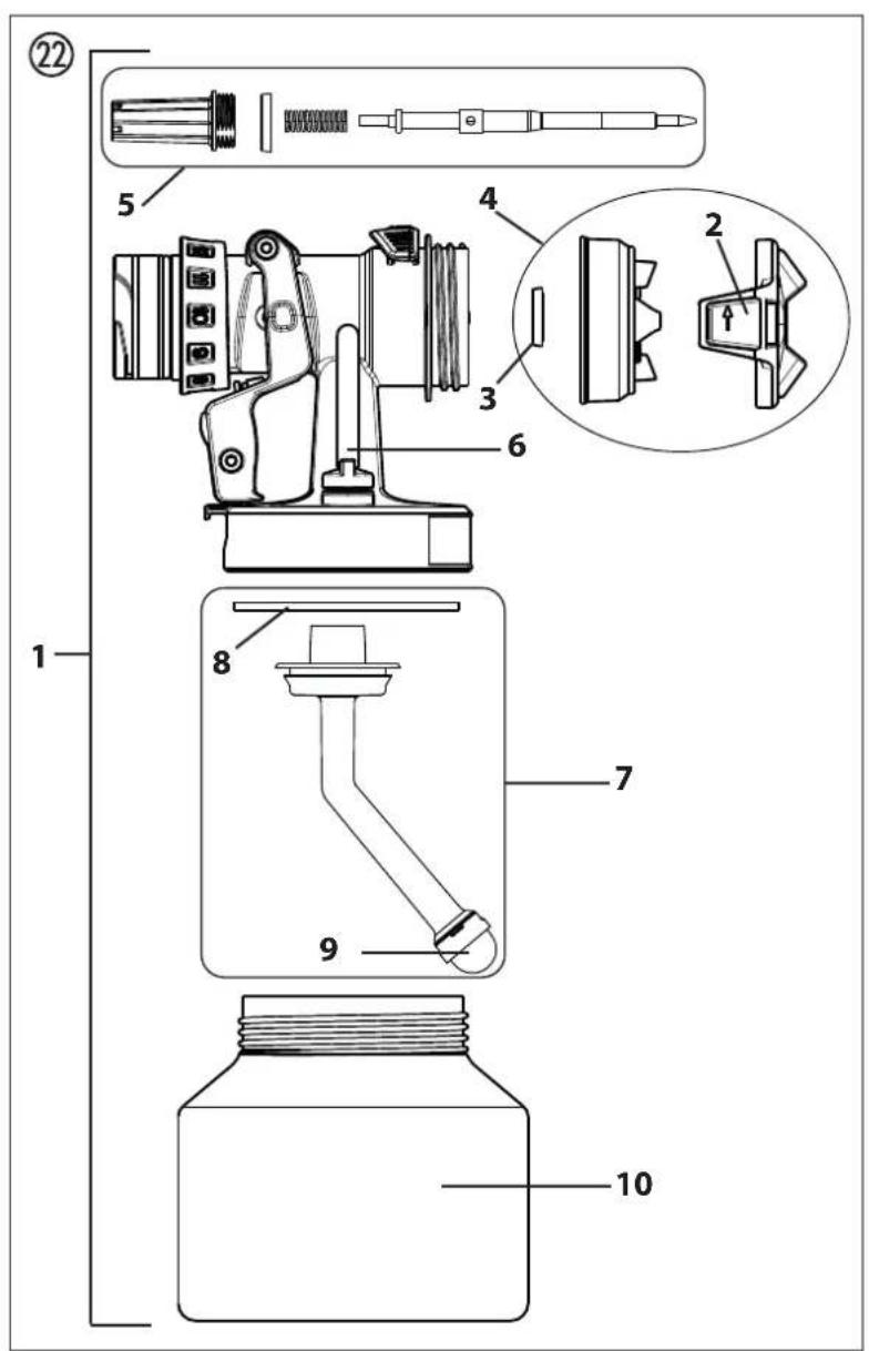
14.3 SPARE PARTS STANDARDSPRAY SPRAY ATTACHMENT (YELLOW) (FIG. 22)
| POS. | ORDER NO. | DESIGNATION |
| 1 | 2430386 | StandardSpray spray attachment (yellow) (with 1000 ml container) |
| 2 | 2434514 | Air cap (StandardSpray, 3 pcs.) |
| 3 | 2323934 | Seal |
| 4 | 2434513 | Spray head service set (StandardSpray) |
| 5 | 2434517 | Needle service set (StandardSpray, 4.1 mm) |
| 6 | 2434516 | Ventilating hose, valve cover, diaphragm |
| 7 | 2434524 | Suction system service set |
| 8 | 2434523 | Container seal (5 pcs.) |
| 9 | 2324248 | Fine feed tube filter (red, 5 pc.) |
| 2324249 | Coarse feed tube filter (white, 5 pc.) | |
| 10 | 2434525 | Container 1000 ml |
| 2315 539 | Lubricating grease |
TESTING OF THE UNIT
For safety reasons, we would recommend having the device checked by an expert as required but at least every 12 months to ensure that it can continue to operate safely.
In the case of unused devices, the check can be postponed until they are next started up.
All (potentially deviating) national inspection and maintenance regulations must also be observed.
If you have any questions, please contact the customer service team at Wagner.
IMPORTANT INFORMATION ON PRODUCT LIABILITY
An EU directive valid since 01.01.1990 specifies that the manufacturer is only liable for his products if all the parts originate from the manufactured or are approved by him, and if the units are mounted and operated properly.
If accessories or spare parts from third parties are used, liability can be partially or completely inapplicable. In extreme cases the responsible authorities can prohibit the use of the entire unit (German industrial employer's liability insurance association and factory inspectorate).
With original WAGNER accessories and spare parts, compliance with all safety regulations is guaranteed.
NOTE ON DISPOSAL
In observance of the European Directive 2012/19/EU on waste electrical and electronic equipment and implementation in accordance with national law, this product is not to be disposed of together with household waste material but must be recycled in an environmentally friendly way!

Wagner or one of our dealers will take back your used Wagner waste electrical or electronic equipment and will dispose of it for you in an environmentally friendly way. Please ask your local Wagner service centre or dealer for details or contact us direct.
EU Declaration of conformity
We declare under sole responsibility that this product conforms to the following relevant stipulations:
2006/42/EC, 2014/30/EU, 2011/65/EU, 2012/19/EU
Applied harmonised norms:
EN 62841-1, EN 50580, EN IEC 55014-1, EN IEC 55014-2,
EN IEC 61000-3-2, EN 61000-3-3, EN 62233
The EU declaration of conformity is enclosed with the product.
If required, it can be re-ordered using order number
2368396.
3 + 2 YEAR GUARANTEE ON THIS WAGNER CONTRACTOR PRODUCT
(Status 03.03.2022)
WAGNER exclusively provides the commercial buyer who has purchased the product from an authorised specialist dealer (hereinafter referred to as the „Customer“) with a guarantee for the products listed on the Internet at https://go.wagner-group.com/3plus2-info in addition to the statutory warranty regulations, unless there is a guarantee exclusion.
The guarantee period for WAGNER products (devices) in the contractor's sector is 36 months and begins with the date of purchase of the initial purchase. This guarantee period is extended by a further 24 months if the product is registered within 28 days of purchase on the Internet at https://go.wagner-group.com/3plus2.
In cases of commercial rental, industrial use (e.g. use in shift operation) or equivalent use, the guarantee period is 12 months due to the significantly higher load. We reserve the right to carry out a check in individual cases and refuse the guarantee where necessary.
If any material, machining or performance defects are identified in the device within the guarantee period, then the guarantee claims must be made immediately and within a period of no more than 2 weeks following discovery of the defect.
The detailed guarantee conditions can be obtained on request from our authorised WAGNER partners (see website or operating instructions) or in text form on our website:
https://go.wagner-group.com/pf-warranty-conditions

Subject to modifications
natural_image
Technical line drawing of a mechanical pulley system with a coiled spring (no text or symbols)6.1 PRODUITS DE REVÊTEMENT APPLICABLES
natural_image
Pure mechanical cross-section diagram without any text, numbers, or symbolsA Jet horizontal plat
natural_image
Technical diagram of a vehicle dashboard with no visible text or symbols13 ELIMINATION DES DÉFAUTS
INDICATION DE MISE AU REBUT
https://go.wagner-group.com/pf-warranty-conditions
natural_image
Technical line drawing of a pulley and rope assembly (no text or symbols)5 INTRODUCTIE IN HET SPUITEN VOLGENS HET XVLP-PROCÉDÉ
natural_image
Pure mechanical cross-section diagram without any text, numbers, or symbolsA horizontale vlakke straal
natural_image
Top-down view of a car dashboard with air vent and control panel (no text or symbols)10 ARBEIDSONDERBREKING
https://go.wagner-group.com/pf-warranty-conditions

natural_image
Technical line drawing of a mechanical pulley system with a separate coil component (no text or symbols)natural_image
Pure mechanical cross-section diagram without any text, numbers, or symbolsnatural_image
Technical line drawing of a vehicle dashboard with no visible text or symbolshttps://go.wagner-group.com/pf-warranty-conditions

14 ACCESSORI E RICAMBI 71
14.1 Accessori 71
14.2 Ricambi FinishControl 71
natural_image
Technical line drawing of a mechanical pulley system with a coiled spring (no text or symbols)natural_image
Pure mechanical component diagram without any text, numbers, or symbolsnatural_image
Technical line drawing of a car dashboard and air vent (no text or symbols)14 ACCESSORI E RICAMBI
14.1 ACCESSORI
POS. N° ORD. NOME
https://go.wagner-group.com/pf-warranty-conditions

14.2 Reservedele FinishControl 82
14.3 Reservedele pistol StandardSpray 82
natural_image
Technical line drawing of a mechanical pulley system with a coiled spring (no text or symbols)2 BESKRIVELSE AF APPARATET (FIG. 1)
POS. BETEGNELSE
natural_image
Pure mechanical component diagram without any text, numbers, or symbolsnatural_image
Technical diagram of a car dashboard with no visible text or symbolshttps://go.wagner-group.com/pf-warranty-conditions

5 INTRODUKTION TILL SPRUTNING MED XVLP ____ 88
6 SPRUTMATERIAL 88
natural_image
Technical line drawing of a mechanical pulley system with a coiled spring (no text or symbols)5 INTRODUKTION TILL SPRUTNING MED XVLP
natural_image
Pure mechanical component diagram without any text, numbers, or symbolsA vågrät flatstråle
natural_image
Top-down view of a car dashboard with air vent and control panel (no text or symbols)https://go.wagner-group.com/pf-warranty-conditions

natural_image
Technical line drawing of a mechanical pulley system with a coiled spring (no text or symbols)natural_image
Pure mechanical component diagram without any text, numbers, or symbolsA jacto plano horizontal
natural_image
Top-down view of a car dashboard with air vent and control panel (no text or symbols)https://go.wagner-group.com/pf-warranty-conditions

natural_image
Technical line drawing of a mechanical pulley system with a coiled spring (no text or symbols)natural_image
Pure mechanical cross-section diagram without any text, numbers, or symbolsnatural_image
Technical line drawing of a car dashboard and air vent system (no text or symbols)AUS Wagner Spraytech Australia Pty. Ltd. 8 – 10 Dansu Court Hallam, Victoria, 3803 Australia Customer Service 1800 924 637 info@wagneraustralia.com.au

- FINISH CONTROL 3500 PLUS
- Inhaltsverzeichnis
- PRÜFUNG DES GERÄTES
- Translation of the original operating instructions
- Contents
- SAFETY REGULATIONS
- All local safety regulations in force must be observed.
- Work area safety
- Electrical safety
- Personal safety
- Power tool use and care
- Service
- Safety instructions for colour application devices
- Risks of Fire and Explosion
- Warning: Danger of injury!
- When spraying paint wear a suitable respirator.
- EXPLANATORY DIAGRAM (FIG. 1)
- THE WAGNER CLICK&PAINT SYSTEM
- DISASSEMBLY OF THE SPRAY GUN
- TECHNICAL DATA
- INTRODUCTION TO SPRAYING USING THE XVLP PROCEDURE
- Function description
- Field of application
- COATING MATERIAL
- COATING MATERIALS SUITABLE FOR USE
- COATING MATERIALS NOT SUITABLE FOR USE
- COATING MATERIALS THAT CAN ONLY BE PROCESSED WITH RELEVANT SPRAY ATTACHMENT (ACCESSORIES)
- PREPARING THE COATING MATERIAL
- Coating material purity:
- SETTING THE SPRAY GUN
- SETTING THE REQUIRED SPRAY PATTERN
- SETTING THE AMOUNT OF MATERIAL (FIG. 5)
- SETTING THE AMOUNT OF AIR (FIG. 6)
- ALIGN THE FEED TUBE
- SPRAYING TECHNIQUE
- BREAKS IN WORK
- TAKING OUT OF OPERATION AND CLEANING
- ASSEMBLY
- MAINTENANCE
- AIR FILTER
- AIR RELIEF VALVE
- Warning
- CORRECTION OF MALFUNCTIONS
- ACCESSORIES AND SPARE PARTS
- ACCESSORIES
- TESTING OF THE UNIT
- IMPORTANT INFORMATION ON PRODUCT LIABILITY
- NOTE ON DISPOSAL
- EU Declaration of conformity
- + 2 YEAR GUARANTEE ON THIS WAGNER CONTRACTOR PRODUCT
- PRODUITS DE REVÊTEMENT APPLICABLES
- INDICATION DE MISE AU REBUT
- INTRODUCTIE IN HET SPUITEN VOLGENS HET XVLP-PROCÉDÉ
- A horizontale vlakke straal
- ARBEIDSONDERBREKING
- ACCESSORI E RICAMBI
- ACCESSORI
- BESKRIVELSE AF APPARATET (FIG. 1)
- BETEGNELSE
- INTRODUKTION TILL SPRUTNING MED XVLP
- A vågrät flatstråle
Brand : WAGNER
Model : FinishControl 3500 Plus
Category : Paint spray