
SuperFinish 21 Pro - Paint spray WAGNER - Free user manual and instructions
Find the device manual for free SuperFinish 21 Pro WAGNER in PDF.


| Product Type | Airless Paint Sprayer |
| Brand | Wagner |
| Model | SuperFinish 21 Pro |
| Power | 900 W |
| Voltage / Frequency | 230-240 V ~ 50 Hz |
| Fuse | 8 A (slow) |
| Max. current draw | 4.2 A |
| Protection rating | IP 54 |
| Max. operating pressure | 207 bar (20.7 MPa) |
| Max. flow rate | 2.1 L/min |
| Flow rate at 12 MPa (water) | 1.6 L/min |
| Max. product temperature | 43 °C |
| Max. viscosity | 15,000 mPas |
| Empty weight | 23.6 kg |
| Hydraulic oil capacity | 0.96 L |
| Vibration level (gun) | < 2.5 m/s² |
| Sound pressure level | ≤ 77 dB(A) |
| Power cable length | 6 m |
| Upper container capacity (optional) | 3.7 L |
| Pump type | Diaphragm pump |
Frequently Asked Questions - SuperFinish 21 Pro WAGNER
User questions about SuperFinish 21 Pro WAGNER
0 question about this device. Answer the ones you know or ask your own.
Ask a new question about this device
Download the instructions for your Paint spray in PDF format for free! Find your manual SuperFinish 21 Pro - WAGNER and take your electronic device back in hand. On this page are published all the documents necessary for the use of your device. SuperFinish 21 Pro by WAGNER.
USER MANUAL SuperFinish 21 Pro WAGNER
10 REPARATUREN AM GERÄT 17
2.2 EXPLOSIONSSCHUTZ

Gefahr
10 REPARATUREN AM GERÄT

go.wagner-group.com/profi
PRÜFUNG DES GERÄTES
https://go.wagner-group.com/pf-warranty-conditions

Translation of the original operating instructions Contents
1 GENERAL SAFETY INSTRUCTIONS 28
2 SAFETY REGULATIONS FOR AIRLESS SPRAYING 30
2.1 Flash point 30
2.2 Explosion protection 30
2.3 Danger of explosion and fire from sources of ignition during spraying work 30
2.4 Danger of injury from the spray jet 30
2.5 Secure spray gun against unintended operation 30
2.6Recoil of spray gun 30
2.7 Breathing equipment as protection against solvent vapors 31
2.8 Prevention of occupational illnesses 31
2.9 Max. operating pressure 31
2.10 High-pressure hose 31
2.11 Electrostatic charging (formation of sparks or flames) 31
2.12 Use of units on building sites and workshops 31
2.13 Ventilation when spraying in rooms 31
2.14 Suction installations 31
2.15 Earthing of the object 31
2.16 Coating material 31
2.17 Cleaning the unit 32
2.18 Work or repairs at the electrical equipment 32
2.19 Maintenance work and breaks 32
2.20 Setup on an uneven surface 32
2.21 Oscillation level 32
3GENERALVIEWOFAPPLICATION/ DESCRIPTIONOFUNIT 33
3.1 Application 33
3.2 Coating material 33
3.2.1 Coating materials with sharp-edged additional materials 33
3.2.2 Filtering 33
3.3 Explanatory diagram 34
3.4 Technical data 35
4 STARTUP 36
4.1 Unit with suction system 36
4.2 Unit with upper hopper 36
4.3 High pressure hose and spray gun 36
4.4 Connection to the mains network 36
4.5 Cleaning preserving agent when starting-up of operation initially 37
4.6 Ventilate unit (hydraulic system) if the sound of inlet valve is not audible 37
4.7 Taking the unit into operation with coating material 37
5 SPRAYING TECHNOLOGY 38
6 HANDLING THE HIGH-PRESSURE HOSE 39
7INTERRUPTIONOFWORK 39
8 CLEANING THE UNIT 40
8.1 Cleaning the unit from the outside 41
8.2 Suction filter 41
8.3 High-pressure filter 41
8.4 Cleaning the Airless spray gun 42
9 SERVICING 42
9.1 General servicing 42
9.2 High-pressure hose 42
10 REPAIRS AT THE UNIT 43
10.1 Inlet valve 43
10.2 Outlet valve 44
10.3 Pressure control valve 44
10.4 Typical wear parts 44
10.5 Remedy in case of faults 45
11 SPARE PARTS AND ACCESSORIES 46
11.1 Super Finish 21 Pro accessories 46
11.2 Spare parts list Super Finish 21 Pro 48
11.3 Spare parts list high-pressure filter 50
11.4 Spare parts list hopper 50
11.5 Spare parts list suction system 51
Testing of the unit 52
Important information on product liability 52
Note on disposal 52
Guarantee declaration 52
EU-declaration 52
European service network 108
1 GENERAL SAFETY INSTRUCTIONS

Read all safety information, instructions, illustrations and technical data provided with this power tool. Failure to observe the following instructions may cause electric shock, fire and/or severe injuries. Keep all safety information and instructions for future reference. The term "power tool" used in this safety information refers to mains-operated power tools (with power cable) and to battery-powered power tools (without power cable).
1. Safety at the workplace
a) Keep your workplace clean and well lit. Disorder or unlit workplaces may result in accidents.
b) Never use the tool in hazardous areas that contain flammable liquids, gases or dusts. Power tools generate sparks that can ignite the dust or vapors.
c) Keep children and other persons away when using the power tool. You can lose control of the tool if you are distracted.
2. Electrical Safety
a) The tool plug must fit into the socket. The plug may not be modified in any form. Do not use adaptor plugs together with protective-earthy tools. Unmodified plugs and suitable sockets reduce the risk of an electric shock.
b) Avoid physical contact with earthed surfaces such as pipes, heating elements, stoves and refrigerators. The risk through electric shock increases if your body is earthed.
c) Keep the equipment away from rain and moisture. The risk of an electric shock increases if water penetrates electrical equipment.
d) Do not misuse the mains lead by carrying the tool by the lead, hanging it from the lead or by pulling on the lead to remove the plug. Keep the lead away from heat, oil, sharp edges or moving tool parts. Damaged or twisted leads increase the risk of an electric shock.
e) If you work outdoors with a power tool, only use extension cables suitable for outdoor use. The use of an extension lead that is suitable for outdoors reduces the risk of an electric shock.
f)) If you cannot avoid using the tool in a damp environment, use a residual current operated circuit-breaker. Using a residual current operated circuit-breaker avoids the risk of electric shock.
3. Safety of Persons
a) Be attentive. Pay attention to what you are doing and work sensibly with a power tool. Do not use the tool if you are tired or under the influence of drugs, alcohol or medication. Just a moment of inattention while using the tool can lead to serious injuries.
b) Wear personal safety equipment and always wear safety goggles. Wearing personal protective equipment, such as dust mask, non-slip safety shoes, safety helmet or ear protection, depending on the type of power tools, reduces the risk of injury.
c) Avoid accidental starting-up. Ensure that the switch is in the "OFF" position before inserting the plug into the socket. Accidents can occur if you carry the power tool while your finger is on the switch or if you connect the power tool to the power supply which it is on.
d) Remove setting tools or wrenches before switching on the power tool. A tool or wrench that is in a rotating tool part can lead to injuries.
e) Avoid an unnatural posture. This ensures that you can control the tool better in unexpected situations.
f) Wear suitable clothing. Do not wear wide clothing or jewellery. Keep your hair, clothes and gloves away from moving parts. Loose clothing, jewellery or long hair can be caught in moving parts.
g) Do not lull yourself into a false sense of security and do not think yourself above the safety rules for electric tools, even if you are familiar with the electric tool following extensive practical experience. Careless use can lead to serious injuries in fractions of a second.
4. Careful Handling and Use of Power Tools
a) Do not overload the tool. Use the power tool designed for the work that you are doing. You work better and safer in the specified performance range if you use the suitable power tool.
b) Do not use power tools whose switch is defective. A power tool that cannot be switched on or off is dangerous and has to be repaired.
c) Remove the plug from the socket before carrying out tool settings, changing accessories or putting the tool away. This precautionary measure prevents unintentional starting of the tool.
d) Store unused power tools so that they are inaccessible to children. Do not let persons use the tool who are not familiar with it or who have not read these instructions. Power tools are dangerous when they are used by inexperienced persons.
e) Take proper care of your tools. Check whether the moving parts function trouble-free and do not jam, whether parts are broken or damaged so that the tool function is impaired. Have damaged parts repaired before using the tool. Many accidents have their origin in power tools that have been maintained badly.
f) Use the power tool, accessories, insert tools, etc. in accordance with these instructions and in a fashion specified for this special tool type. Take the working conditions and the activity to be carried out into consideration. The use of power tools for purposes other than the intended ones can lead to dangerous situations.
g) Keep the handles and grip surfaces dry, clean and free of oil and grease. Slippery handles and grip surfaces hamper safe operation and control of the electric tool in unforeseen situations.
5. Service
a) Have your tool repaired only by qualified specialist personnel and only with original spare parts. This ensures that the tool safety is maintained.
b) If the supply cord is damaged, it must be replaced by the manufacturer or it's service agent or a similarly qualified person in order to avoid a safety hazard.
2 SAFETY REGULATIONS FOR AIRLESS SPRAYING
All local safety regulations in force must be observed.
The following sources are just a sample of those containing safety requirements for Airless spraying.
a) The European Standard, Spray equipment for coating materials - safety regulations, (EN 1953).
The following safety regulations are to be observed in order to ensure safe handling of the Airless high-pressure spraying unit.
2.1 FLASH POINT

Only spray coating materials with a flash point of 21^ or higher.
The flash point is the lowest temperature at which vapors develop from the coating material. These vapors are sufficient to form an inflammable mixture over the air above the coating material.
2.2 EXPLOSION PROTECTION

Do not use the unit in work places which are covered by the explosion protection regulations. The unit is not designed to be explosion protected. Do not operate the device in explosive areas (zone 0, 1 and 2). Explosive areas are, for example, places where paints are stored and locations in direct proximity to the object being sprayed. Keep the device at least 3m from the object you are spraying.
2.3 DANGER OF EXPLOSION AND FIRE FROM SOURCES OF IGNITION DURING SPRAYING WORK

There must be no sources of ignition such as, for example, open fires, lit cigarettes, cigars or tobacco pipes, sparks, glowing wires, hot surfaces, etc. in the vicinity.
2.4 DANGER OF INJURY FROM THE SPRAY JET

Attention, danger of injury by injection! Never point the spray gun at yourself, other persons or animals.
Never use the spray gun without spray jet safety guard.
The spray jet must not come into contact with any part of the body.
In working with Airless spray guns, the high spray pressures arising can cause very dangerous injuries. If contact is made with the spray jet, coating material can be injected into the skin. Do not treat a spray injury as a harmless cut. In case of injury to the skin by coating material or solvents, consult a doctor for quick and correct treatment. Inform the doctor about the coating material or solvent used.
Always secure the spray gun when mounting or dismounting the tip and in case of interruption to work.
2.6 RECOIL OF SPRAY GUN

When using a high operating pressure, pulling the trigger guard can effect a recoil force up to 15 N.
If you are not prepared for this, your hand can be thrust backwards or your balance lost. This can lead to injury.
2.7 BREATHING EQUIPMENT AS PROTECTION AGAINST SOLVENT VAPORS
Wear breathing equipment during spraying work
A breathing mask is to be made available to the user.
2.8 PREVENTION OF OCCUPATIONAL ILLNESSES
Wear safety goggles.
Wear hearing protection.
Protective clothing, gloves and possibly skin protection cream are necessary for the protection of the skin.
Observe the regulations of the manufacturer concerning coating materials, solvents and cleaning agents in preparation, processing and cleaning units.
The permissible operating pressure for the spray gun, spray gun accessories, unit accessories and high-pressure hose must not fall short of the maximum operating pressure of 20.7 MPa (207 bar).
2.10 HIGH-PRESSURE HOSE

Danger
Attention, danger of injury by injection! Wear and tear and kinks as well as usage that is not appropriate to the purpose of the device can cause leakages to form in the high-pressure hose. Liquid can be injected into the skin through a leakage.
- High-pressure hoses must be checked thoroughly before they are used.
- Replace any damaged high-pressure hose immediately.
- Never repair defective high-pressure hoses yourself!
- Avoid sharp bends and folds: the smallest bending radius is about 20cm .
- Do not drive over the high-pressure hose. Protect against sharp objects and edges.
- Never pull on the high-pressure hose to move the device.
- Do not twist the high-pressure hose.
- Do not put the high-pressure hose into solvents. Use only a wet cloth to wipe down the outside of the hose.
- Lay the high-pressure hose in such a way as to ensure that it cannot be tripped over.

Only use WAGNER original-high-pressure hoses in order to ensure functionality, safety and durability.
2.11 ELECTROSTATIC CHARGING (FORMATION OF SPARKS OR FLAMES)

Danger
Electrostatic charging of the unit may occur during spraying due to the flow speed of the coating material. These can cause sparks and flames upon discharge. The unit must therefore always be earthed via the electrical system. The unit must be connected to an appropriately-grounded safety outlet.
An electrostatic charging of spray guns and the high-pressure hose is discharged through the high-pressure hose. For this reason the electric resistance between the connections of the high-pressure hose must be equal to or lower than 1M
2.12 USE OF UNITS ON BUILDING SITES AND WORKSHOPS
The unit may only be connected to the mains network via a special feeding point with a residual-current device with INF ≤ 30mA
2.13 VENTILATION WHEN SPRAYING IN ROOMS
Adequate ventilation to ensure removal of the solvent vapors has to be ensured.
2.14 SUCTION INSTALLATIONS
The are to be provided by the unit user in accordance with the corresponding local regulations.
2.15 EARTHING OF THE OBJECT
The object to be coated must be earthed.
(Building walls are usually earthed naturally)
2.16 COATING MATERIAL
Caution against dangers that can arise from the sprayed substance and observe the text and information on the containers or the specifications given by the substance manufacturer. Do not spray any liquid of unknown hazard potential.
2.17 CLEANING THE UNIT
When cleaning the gun, only rinse when the nozzle is removed and rinse at low pressure.

When cleaning the unit with solvents, the solvent should never be sprayed or pumped back into a container with a small opening (bunghole). An explosive gas/air mixture can arise. Only use an earthed container made from metal. To earth the gun, hold it firmly on the edge of the container.

Danger of short-circuits caused by water ingression! Never spray down the unit with high-pressure or high-pressure steam cleaners.
2.18 WORK OR REPAIRS AT THE ELECTRICAL EQUIPMENT
These may only be carried out by a skilled electrician. No liability is assumed for incorrect installation. Unplug the power plug from the outlet before carrying out any repair work.
2.19 MAINTENANCE WORK AND BREAKS
Before carrying out any work on the device and during any work break, release the pressure in the spray gun and high-pressure hose. Secure the spray gun's trigger guard and switch off the device.
2.20 SETUP ON AN UNEVEN SURFACE
If possible do not use the unit on an inclined surface since the unit tends to wander through the resulting vibrations.
The specified oscillation level has been measured according to a standard test procedure and can be used to compare against electric tools. The oscillation level is also for determining an initial assessment of the vibrational strain.
Attention! The vibration emission value can differ from the specified value when the electric tool is actually in use, depending on how the electric tool is being used. It is necessary to specify safety measures to protect the operating personnel. These measures are based on an estimated shutdown during the actual conditions of use (all parts of the operating cycle are taken into consideration here, for example periods when the electric tool is switched off, and, when it is switched on but running without any load).
3 GENERAL VIEW OF APPLICATION/ DESCRIPTION OF UNIT
3.1 APPLICATION
SF 21 Pro is an electric driven unit for the airless atomization of different painting materials. Also it is able to feed the internal feeded paint roller, which is available as accessory.
SF 21 Pro is made for jobs in the workshop and on the building site.
The SF 21 Pro's device output is designed so that dispersions can be processed indoors and outdoors for small to medium-sized objects.
When painting, the device is suitable for all kinds of typical painting jobs, e.g.:
doors, door frames, balustrades, furniture, woodencladding, fences, radiators (heating) and steel parts.
We recommend using the top container for paintwork.
3.2 COATING MATERIAL
Diluting lacquers and paints or those containing solvents, two-component coating materials, dispersion and latex paints.
No other materials should be used for spraying without WAGNER's approval.

Pay attention to the Airless quality of the coating materials to be processed.
The unit is able to process coating materials with up to 15,000 mPas. If highly viscous coating materials cannot be taken in or the performance of the unit is to low, the paint must be diluted in accordance with the manufacturer's instructions.

Attention: Make sure, when stirring up with motor-driven agitators that no air bubbles are stirred in. Air bubbles disturb when spraying and can, in fact, lead to interruption of operation.
3.2.1 COATING MATERIALS WITH SHARP-EDGED ADDITIONAL MATERIALS
These particles have a strong wear and tear effect on valves and tips, but also on the heating hose and spray gun. This impairs the durability of these wearing parts considerably.
3.2.2 FILTERING
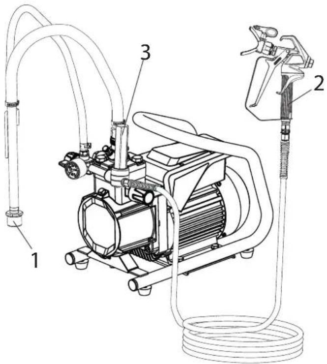
Sufficient filtering is required for fault-free operation. To this purpose the unit is equipped with a suction filter (Item 1) and an insertion filter in the spray gun (Item 2). Regular inspection of these filters for damage or soiling is urgently recommended.
A high-pressure filter (Item 3) -available as accessory- is rising up the filtering surface and will make the work more comfortable.
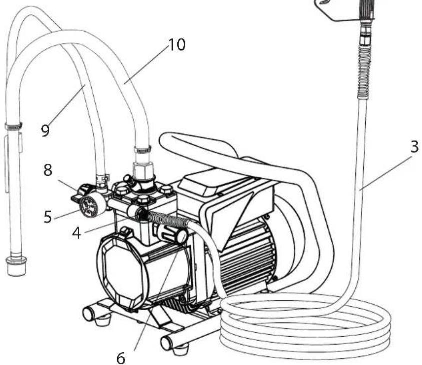
3.3 EXPLANATORY DIAGRAM
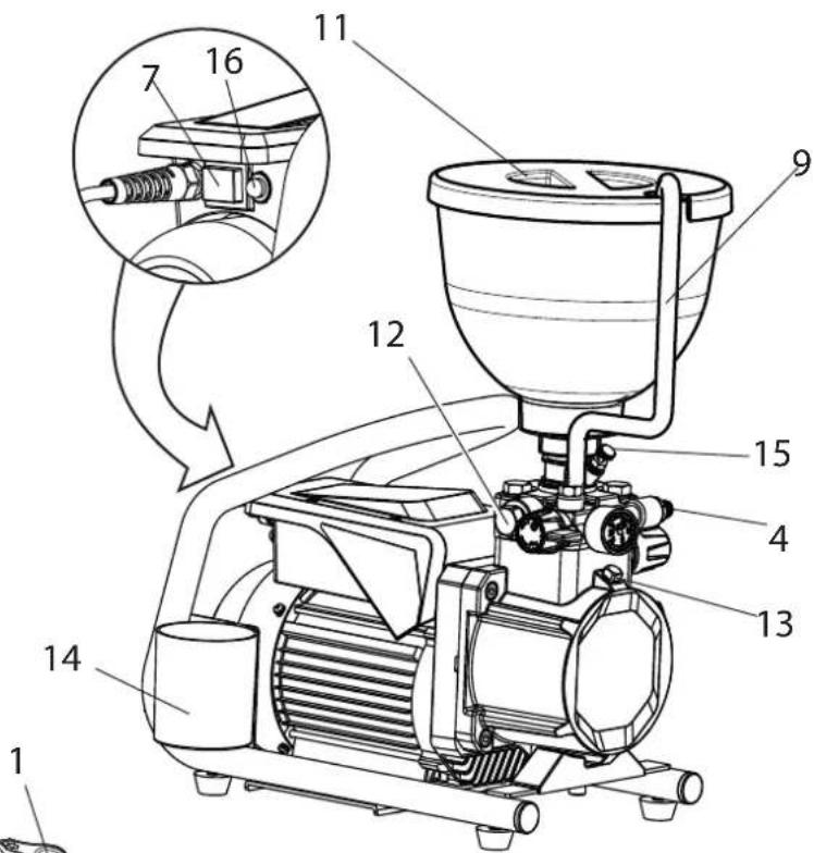
1 Tip guard with airless tip
2 Spray gun
3 High-pressure hose
4 Connection for high-pressure hose
5 Pressure gauge
6 Pressure control valve
7 ON/OFF switch
8 Pressure relief valve
9 Return hose
10 Suction hose
11 Hopper*
12 Outlet valve
13 Oil dipstick
14 Cleaning Container
15 Inlet valve pusher
16 Fuse
17 Tool bag (no fig.)
*Accessory. The actual scope of the delivery depends on how the Spray Pack is configured.
3.4 TECHNICAL DATA
| 230-240 V 110 V | ||
| Voltage : 230-240 V AC, 50 Hz 110 | 0-120 V AC, 50 Hz | |
| Fuses : 8 A time-lag 16 A time-lag | ||
| Unit connecting line : 6 m long, 3 x 1.0 mm² 6 m long, 3 x 1.5 mm² | ||
| Max. current consumption: 4.2 A | 9.0 A | |
| Degree of protection : IP 54 | ||
| Rated input of device: 900 W | 750 W | |
| Max. operating pressure : | 20.7 MPa (207 bar) | |
| Max. volume flow : | 2.1 l/min | |
| Volume flow at 12 MPa(120 bar) with water : | 1.6 l/min | 1.8 l/min |
| Max. temperature of the coating material : | 43 °C | |
| Max. viscosity : | 15,000 mPas | |
| Empty weight : | 23.6 kg | 23.9 kg |
| Hydraulic oil filling quantity : | 0.96 liter | |
| Max. vibration at the spraygun : | lower than 2.5 m/s² | |
| Max. sound pressure level: | 77 dB (A)* | |
*Place of measurement: 1 m distance from unit and 1.60 m above floor, 12 MPa (120 bar) operating pressure, reverberant floor
Transportation in vehicle
Secure the unit in the vehicle by means of suitable fasteners. The device can be placed on its side if necessary. In this case, please ensure that no attachments can be damaged. Attention: Paint or solvent residues can escape from the connections!
4 STARTUP
| i | Press the inlet valve pusher before start up. This ensures that the valve is not blocked or clogged. |
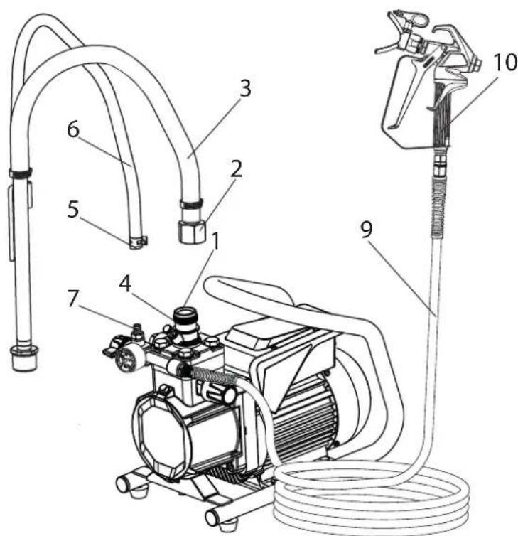
4.1 UNIT WITH SUCTION SYSTEM
- Ensure that the sealing surfaces of the connections are clean.
Ensure that the red inlet (1) is inserted in the coating material inlet (4).
- Use the enclosed 41mm wrench to screw the union nut (2) at the suction hose (3) onto the coating material inlet (4) and tighten it.
- Put the return hose (5) on the connection (6) and fix it with the clamp (7).
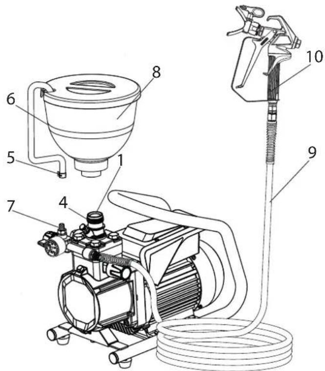
4.2 UNIT WITH UPPER HOPPER
- Ensure that the sealing surfaces of the connections are clean. Ensure that the red inlet (1) is inserted in the coating material inlet (4).
- Put the return hose (5) on the connection (6) and fix it with the clamp (7).
- Screw the upper hopper (8) onto the coating material inlet (4).
4.3 HIGH PRESSURE HOSE AND SPRAY GUN
- Screw the high pressure hose (9) onto the hose connection
- Screw the spray gun (10) onto the high pressure hose
- Tighten all union nuts on high pressure hose so that no coating material can escape.
- Screw the tip holder with the selected tip onto the spray gun, align tip and tighten union nut.

When unscrewing the high pressure hose, hold firmly on the hose connection with a 22mm wrench.
4.4 CONNECTION TO THE MAINS NETWORK

Connection must always be carried out via an appropriately grounded safety outlet with residual-current-operated circuit-breaker.
Before connecting the unit to the mains supply, ensure that the line voltage matches that specified on the unit's rating plate.
4.5 CLEANING PRESERVING AGENT WHEN STARTING-UP OF OPERATION INITIALLY
Unit with suction tube
- Immerse the suction system into a container filled with a suitable cleaning agent (recommendation: water).
Unit with hopper
- Fill up hopper with a suitable cleaning agent (recommendation; water).
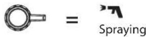
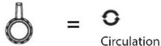
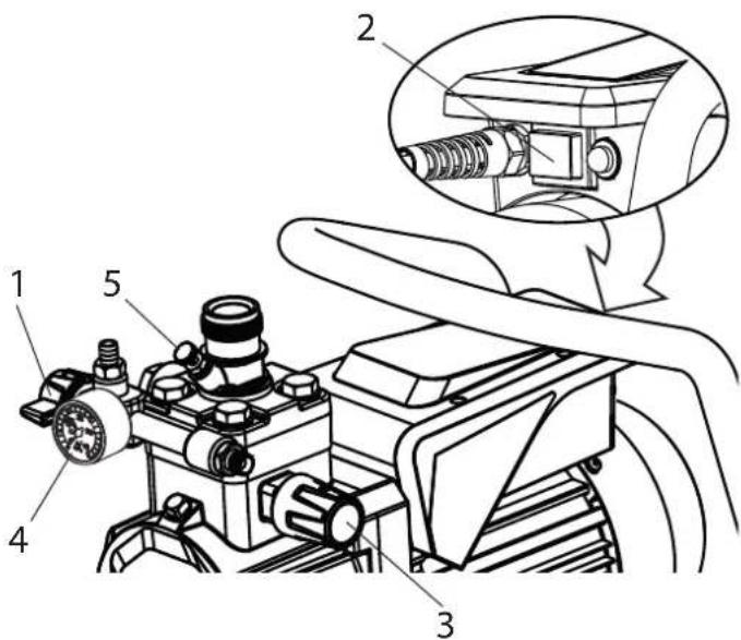
- Set pressure relief valve (1) to (circulation).
- Switch the device on (Pos. I) using the ON/OFF switch (2).
- Slowly turn the pressure regulating knob (3) to the right.
- Wait until you can hear the sound of the inlet valve and cleaning agent flows from the return hose.
- Turn the pressure regulating knob (3) back approx. one rotation.
- Set pressure relief valve (1) to spray). Pressure is rising up inside the high pressure hose (visible at pressure gauge (4)).
- Point the tip of the spray gun to inner wall of an open and empty metal container and pull the trigger at the spray gun.
- The pressure is increased by turning the pressure regulating knob (3) to the right. Set approx. 10MPa (100 bar) at the pressure gauge.
- Spray the cleaning agent out of the unit for approx. 1 - 2 min. (~5 litres) into the open collecting container.
4.6 VENTILATE UNIT (HYDRAULIC SYSTEM) IF THE SOUND OF INLET VALVE IS NOT AUDIBLE
- Switch the device on (Pos. I) using the ON/OFF switch (2).
- Turn pressure regulating knob (3) approx. three revolutions to the left.
- Set pressure relief valve (1) to (circulation). The hydraulic system is ventilated. Leave the unit on for two to three minutes.
- Then slowly turn pressure regulating knob (3) to the right until you can hear the sound of the inlet valve.
- Press inlet valve pusher (5). Sound of the inlet valve is audible.
- If not, repeat points 2 to 5 or tap gently with a small hammer on the flat of the outlet valve.
4.7 TAKING THE UNIT INTO OPERATION WITH COATING MATERIAL
Unit with suction tube
- Immerse the suction system into a container filled with coating material.
Unit with hopper
- Fill coating material into the hopper.
- Set pressure relief valve (1) to (circulation).
- Switch the device on (Pos. I) using the ON/OFF switch (2).
- Slowly turn the pressure regulating knob (3) to the right. When the noise of the valves changes, the unit is bled and takes in coating material.
- If coating material exits from the return hose, turn the pressure regulating knob (3) back approx. 1 rotation.
- Set pressure relief valve (1) to (may).
Pressure is rising up inside the high pressure hose (visible at pressure gauge (4)).
- Pull the trigger of the spray gun and spray into an open and empty container in order to remove the remaining cleaning agent from the unit. When coating materials exits from the tip, close the spray gun.
- Adjust the spraying pressure by turning the pressure regulating knob (3).
- The unit is ready to spray.
5 SPRAYING TECHNIQUE
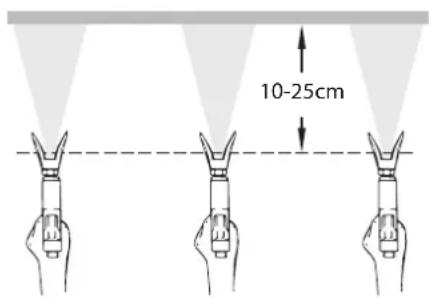
- The key to a high-quality result is the even coating of the entire surface. Move your arm at a uniform speed and hold the spray gun at a constant distance from the surface. The ideal distance is around 10 - 25cm between the spray nozzle and the surface. (Fig. A)
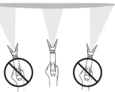
- Hold the spray gun parallel to the surface. Move the gun using your entire arm, not just the wrist. (Fig. B)
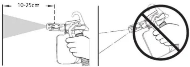
- Hold the spray gun at right angles to the surface. Otherwise the coating will be thicker at one end than the other. (Fig. C)
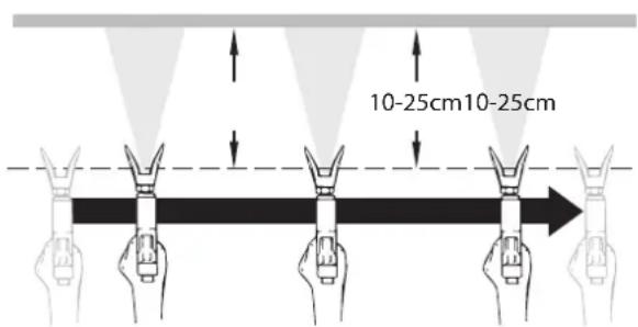
- Pull the trigger guard once you have started the movement. Release the trigger again before you finish the movement. (Fig. D) Avoid interruptions within the spray surface.
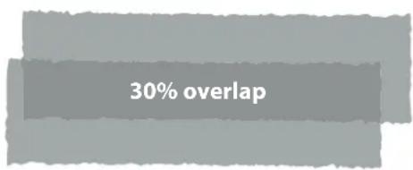
- Allow each stripe to overlap by around 30% . This will ensure even coating. (Fig. E)
- Use the lowest possible pressure setting to create the desired spray pattern in order to minimise spray mist.
- To achieve perfect surfaces at varnishing works, special accessories are available at Wagner, e.g. FineFinish tips. Your Wagner dealer will advise you.
A)
B)
C)
D)
E)
6 HANDLING THE HIGH-PRESSURE HOSE
The unit is equipped with a high-pressure hose specially suited for diaphragm pumps.

Danger
Danger of injury through leaking high-pressure hose. Replace any damaged high-pressure hose immediately.
Never repair defective high-pressure hoses yourself!
The high-pressure hose is to be handled with care. Avoid sharp bends and folds: the smallest bending radius is about 20~cm
Do not drive over the high-pressure hose. Protect against sharp objects and edges.
Never pull on the high-pressure hose to move the device.
Make sure that the high-pressure hose cannot twist. This can be avoided by using a Wagner spray gun with a swivel joint and a hose system.

When using the high-pressure hose while working on scaffolding, it is best to always guide the hose along the outside of the scaffolding.

The risk of damage rises with the age of the high-pressure hose.
Wagner recommends replacing high-pressure hoses after 6 years.

Only use WAGNER original-high-pressure hoses with internal heating in order to ensure functionality, safety and durability.
7 INTERRUPTION OF WORK
- Set pressure relief valve to (pressure relief, circulation).
- Switch the unit off using the ON/OFF switch (Pos. 0).
- Pull trigger of the spray gun to decrease the pressure of the high pressure hose and the spray gun.
- Secure the spray gun, refer to the operating manual of the spray gun.
- Remove tip from tip holder and store the tip in a small vessel with suitable cleaning agent.
- Leave the suction system immersed in the coating material or immerse it in the corresponding cleaning agent. The suction filter and unit should not dry out.
- Cover the material container in order to prevent the paint from drying.

In using quick-drying or two-component coating materials, do not fail to rinse unit through with a suitable cleaning agent during the processing period.
8 CLEANING THE UNIT
A clean state is the best method of ensuring operation without problems. After you have finished spraying, clean the unit. Under no circumstances may coating material rests dry and harden in the unit. The cleaning agent used for cleaning (only with a flash point above 21^ ) must be suitable for the coating material used.

Warm water improves the cleaning effect in the case of water-dilutable coating materials.
- Secure the spray gun, refer to the operating manual of the spray gun.
Remove and clean the tip and tip holder.
- Unit with suction system
- Set pressure relief valve to (circulation).
- Switch the device on (Pos. I) using the ON/OFF switch.
- Remove the suction system from the material container. The return pipe hose remains over the material container until barely any coating material comes out.
- Immerse the suction system into a container filled with a suitable cleaning agent
- Turn the pressure control valve back in order to set a minimal spraying pressure.
- Set pressure relief valve to spray).
- Pull the trigger of the spray gun in order to pump the remaining coating material from the suction hose, high-pressure hose and the spray gun into an open container (if appropriate, increase the pressure at the pressure control valve slowly in order to obtain a higher material flow).

Attention
The container must be earthed in case of coating materials which contain solvents (e.g. by using a metal container).

Attention
Caution! Do not pump or spray in container with small opening (bunghole)! See safety regulations.
- Set pressure relief valve to (circulation).
- Pump suitable cleaning agent in the circuit for several minutes.

The cleaning effect is increased by alternatively opening and closing the spray gun.
- Set pressure relief valve to (spray).
- Pump the remaining cleaning agent into an open container until the pump is empty.
- Set pressure relief valve to circulation).
- Switch the unit off using the ON/OFF switch (Pos. 0).
- Unit with upper hopper
- Set pressure relief valve to (circulation).
- Switch the device on (Pos. I) using the ON/OFF switch.
-
Turn the pressure control valve back in order to set a minimal spraying pressure.
-
Set pressure relief valve to (spray).
- Pull the trigger of the spray gun in order to pump the remaining coating material from the hopper, high-pressure hose and the spray gun into an open container (if appropriate, increase the pressure at the pressure control valve slowly in order to obtain a higher material flow).

Attention
The container must be earthed in case of coating materials which contain solvents (e.g. by using a metal container).

Attention
Caution! Do not pump or spray in container with small opening (bunghole)! See safety regulations.
- Fill up hopper with suitable cleaning agent.
- Set pressure relief valve to (circulation).
- Pump suitable cleaning agent in the circuit for several minutes.
- Set pressure relief valve to (spray).
- Pump the remaining cleaning agent from the hopper, high-pressure hose and the spray gun into an open container
- Set pressure relief valve to circulation).
- Switch the unit off using the ON/OFF switch (Pos. 0).
8.1 CLEANING THE UNIT FROM THE OUTSIDE

First unplug the power plug from the outlet.
Danger of short-circuits caused by water ingression! Never spray down the unit with high-pressure or high-pressure steam cleaners.

Do not put the high-pressure hose into solvents. Use only a wet cloth to wipe down the outside of the hose.
Wipe down unit externally with a cloth which has been immersed in a suitable cleaning agent.
8.2 SUCTION FILTER

Clean filters always ensure maximum volume, constant spray pressure and problem-free functioning of the unit.
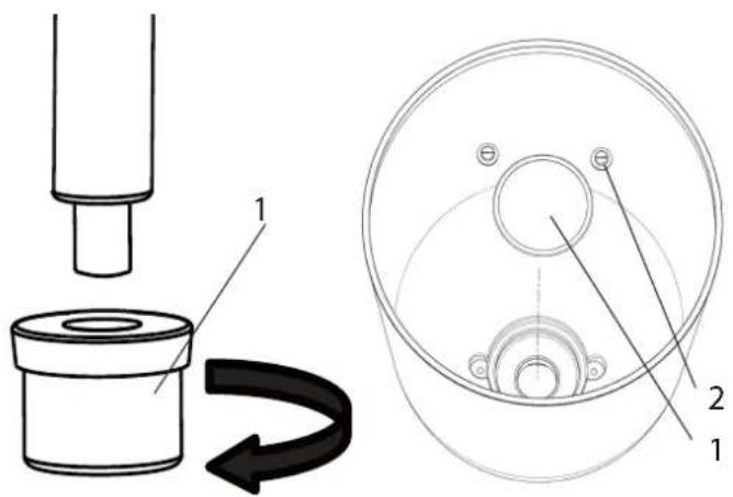
suction system hopper
Unit with suction system
- Unscrew the filter (Item 1) from the suction tube.
- Clean or replace the filter.
Carry out cleaning with a hard brush and a corresponding cleaning agent.
Unit with hopper
- Release screws with a screwdriver (Item 2).
- Lift and remove filter disk with a screwdriver
- Clean or replace the filter disk.
Carry out cleaning with a hard brush and a corresponding cleaning agent.
8.3 HIGH-PRESSURE FILTER
- Set pressure relief valve to (pressure relief, circulation).
- Switch the unit off using the ON/OFF switch (Pos. 0).
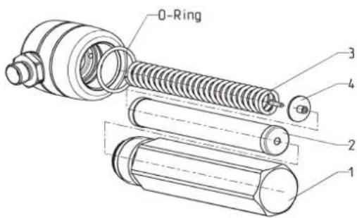
- Open the high-pressure filter and clean the filter insert. To do so:
- Unscrew the filter housing (1) by hand.
- Remove the filter insert (2) and pull out the bearing spring (3).
- Clean all the parts with the corresponding cleaning agent. If compressed air is available - blow through the filter insert and bearing spring.
- When mounting the filter ensure that the bearing ring (4) in the filter insert is positioned correctly and check the O-ring at the filter housing for damage.
- Screw on the filter housing by hand until it stops (a higher tightening force only impedes later dismantling).
8.4 CLEANING THE AIRLESS SPRAY GUN
- Rinse the Airless spray gun with a suitable cleaning agent under lower operating pressure.
- Clean the tip thoroughly with a suitable cleaning agent so that no suitable coating material rests remain.
- Do not store the tip in solvent because this reduces the durability considerably.
- Clean the outside of the Airless spray gun thoroughly.
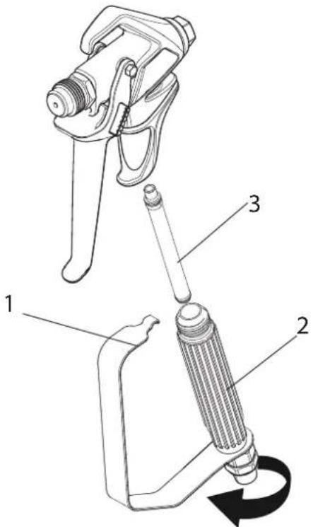
Insertion filter in the Airless spray gun
- Unclip the top of the trigger guard (1) from the gun head.
- Using the bottom of the trigger guard as a wrench, loosen and remove the handle assembly (2) from the gun head.
- Pull the old filter (3) out of the gun head. Clean or replace.
- Slide the new filter, tapered end first, into the gun head.
- Thread the handle assembly into the gun head. Tighten with the trigger wrench.
- Snap the trigger guard back onto the gun head.
9 SERVICING
9.1 GENERAL SERVICING

We strongly recommend having an annual check carried out by technicians for safety reasons. Please observe all the applicable national regulations.
Minimum check before every startup:
- Check the high-pressure hose, spray gun with rotary joint, power supply cable with plug for damage.
- Check whether the pressure gauge can be read.
Check at periodical intervals:
- Check inlet and outlet valve according wear. Clean it and replace worn out parts.
- Check all filter inserts (spray gun, suction system) clean it and replace if necessary.
9.2 HIGH-PRESSURE HOSE
Inspect the high-pressure hose visually for any notches or bulges, in particular at the transition in the fittings. It must be possible to turn the union nuts freely. A conductivity of less than
1 MΩ must exist across the entire length.
| Attention | Have all the electric tests carried by the Wag-ner Service. |
| i | The risk of damage rises with the age of the high-pressure hose. Wagner recommends replacing high-pres-sure hoses after 6 years. |
10 REPAIRS AT THE UNIT

Switch the unit off. Before all repair work: Unplug the power plug from the outlet.
10.1 INLETVALVE
Disassembly
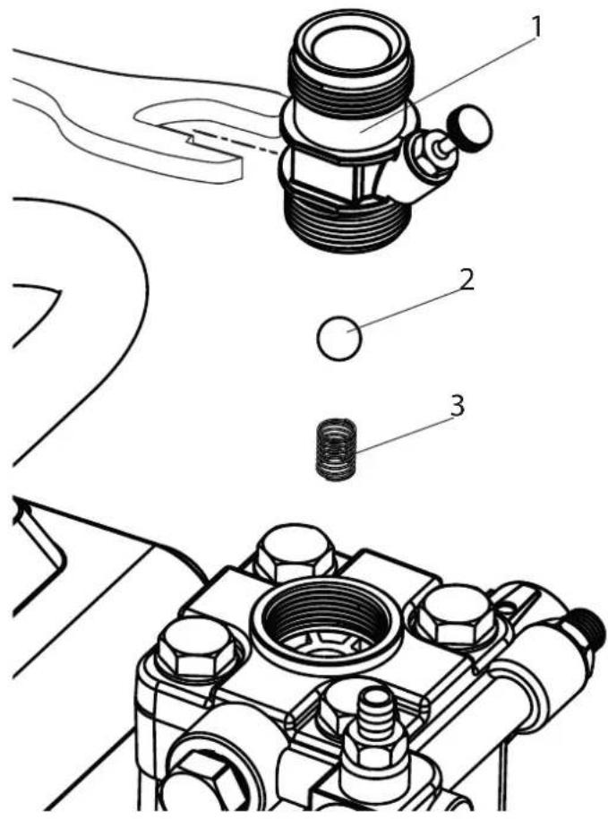
- Place the enclosed 30mm wrench on the housing (1).
- Loosen the housing (1) with light blows of a hammer on the end of the wrench.
- Screw out the housing from the paint section.
- Remove the ball (2) and spring (3).
- Clean and check all parts for damage and replace if necessary.
Installation
- Replace the ball (2) and spring (3).
- Screw the housing (1) into the pump section.
- Tighten the housing with the 30~mm wrench and tighten with three light blows of the hammer on the end of the wrench. (Corresponds to approx. 65-70 Nm tightening torque).
10.2 OUTLETVALVE
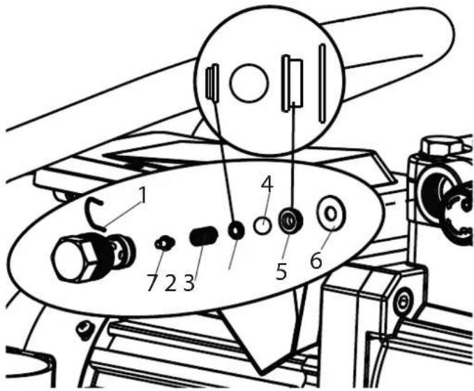
- Use a 22mm wrench to screw the outlet valve from the paint section.
- Carefully remove the clasp (1) using the enclosed screwdriver. The pressure spring (2) pushes out ball (4) and valve seat (5).
- Clean or replace the components.
- Check the O-ring (7) for damage.
- Check the installation position when mounting the spring support ring (3) (clipped onto spring (2)), outlet valve seat (5) and seal (6), refer to figure.
Please also pay particular attention to the following notes:
- The torque for fitting the outlet valve is 57-60 Nm.
- During normal operation, check regularly whether the outlet valve has become loose.
- Always also replace the seal (6) if you have dismantled the outlet valve, regardless of which component you want to replace. Note: The seal (6) is located inside the paint section.
- The groove in the seal (6) points outwards when replaced.
10.3 PRESSURE CONTROL VALVE

Danger
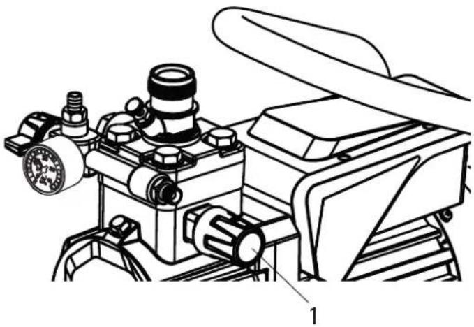
Only have the pressure control valve (1) replaced by the customer service.
The max. operating pressure has to be reset by the customer service.
10.4 TYPICAL WEAR PARTS
Despite the use of high-quality materials the highly abrasive effect of the paints means that wear can occur at the following parts:
Inlet valve (spare part Order No.: 2443943)
For replacing refer to Section 10.1
(failure becomes noticeable through performance loss and/or poor or no suction)
Outlet valve (spare part Order No.: 2443904)
For replacing refer to Section 10.2
(failure becomes noticeable through performance loss and/or poor suction) The outlet valve is usually considerably more durable than the inlet valve. Thorough cleaning may already help here.
10.5 REMEDY IN CASE OF FAULTS
| TYPE OF MALFUNCTION | WHAT ELSE? POSSIBLE CAUSE | MEASURES FOR ELIMINATING | THERE MALFUNCTION |
| Unit does not start The device does not start after it has been plugged in and switched on. | No voltage applied Check voltage supply | ||
| Unit fuse has triggered Let the motor cool down and push the fuse back in. | |||
| Capacitor in terminal box burned out | Replace capacitor | ||
| Unit does not suck in Air bubbles do not exit at the return hose | Inlet/outlet valve clogged / worn | Remove the valves and clean then (=> refer to Section Pkt.10.1/10.2) / replace worn parts | |
| Pressure control valve turned down completely | Turn the pressure control valve to the right un-til the stop is reached | ||
| Air bubbles exit from the return hose | Unit is sucking in outside air | Check if Suction system is properly tightened | |
| Check if red inlet is installed in the inlet valve housing (=> see 4.1) | |||
| Unit does not generate pressure | Unit has sucked in Air in the oil circuit (Possible reasons: long time not used, replacement of diaphragm or hydraulic oil change | Bleed the oil circuit in the unit by turning the pressure control valve completely to the left (until overturning) and let it run approx. 2 - 3 min. Then turn the pressure control valve to the right and set the spraying pressure (repeat process several times, if necessary). | |
| Unit reached pressure, but the pressure collapses, also at the pressure gauge, during spraying. | Suction filter clogged Check the suction filter. If necessary, clean/ replace | ||
| Paint cannot be worked in this state. Due to its properties the paint clogs the valves (inlet valve) and the delivery rate is too low. | Dilute the paint | ||
| Unit reached pressure, but the pressure collapses during spraying. pressure gage still shows high pressure | Clogged filter do not let enough paint pass | Check/clean the (high-pressure filter) gun filter | |
| Tip clogged Clean the tip | |||
| Unit does not generate the max. pressure possible. Paint neverthe-less exits at the return hose. | Relief valve defective Please contact Wager Customer Service | ||
11 SPARE PARTS AND ACCESSORIES
11.1 SUPER FINISH 21 PRO ACCESSORIES
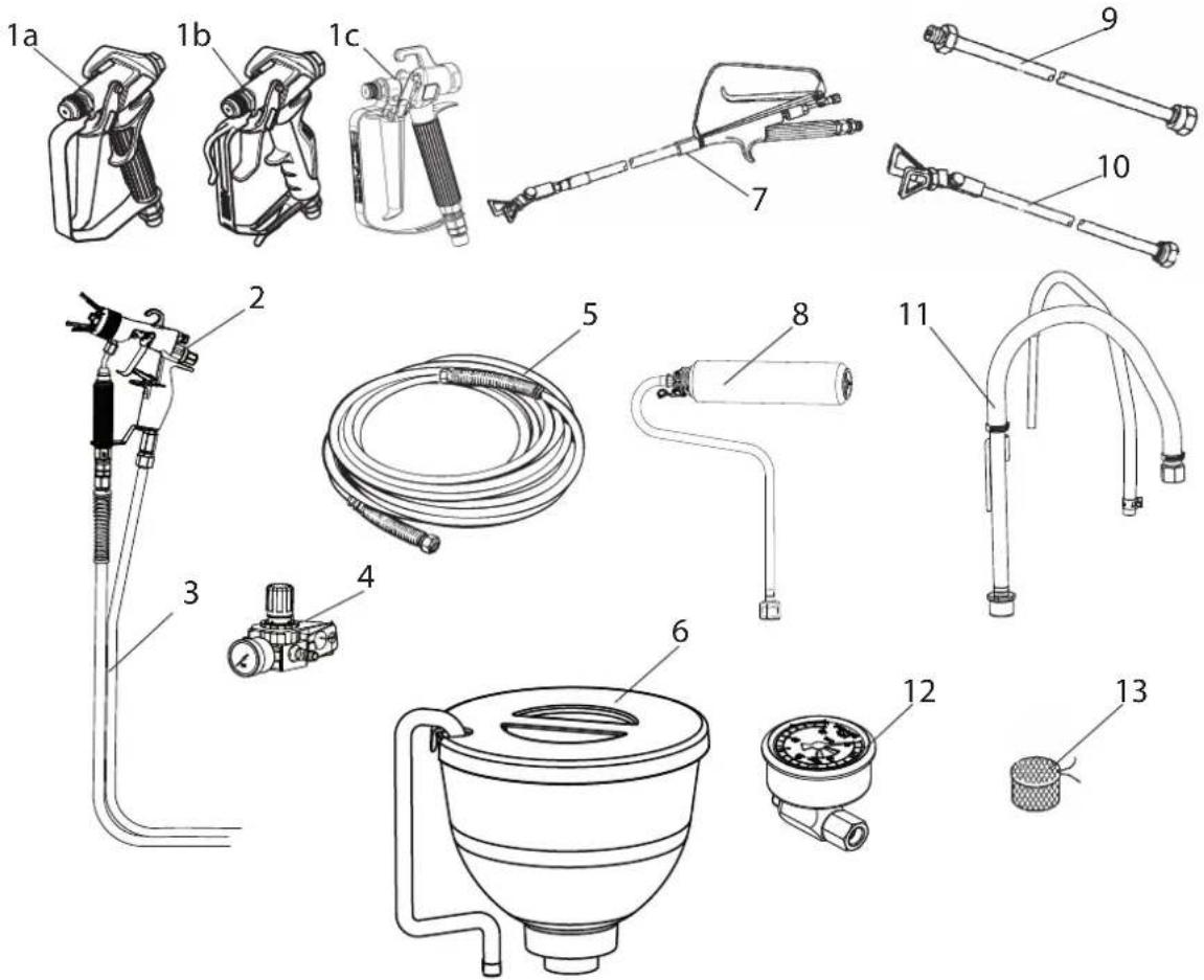
Accessories:
| ITEM | DESIGNATION ORDER NO. | |
| 1a | Spray gun Vector Pro (2-finger) | 0538 041 |
| Spray gun Vector Pro (4-finger) | 0538 040 | |
| 1b | Spray gun Vector Grip (2-finger and 4-finger) | 0538 043 |
| 1c | Spray gun AG-14(stainless steel) | 0502081A |
| 2 AirCoat spray gun AC 4500 (blue) 2368 269 | ||
| 3 Double hose 9984 564 | ||
| 4 AirCoat-controller set 0340 250 | ||
| 5 HP hose DN6-PN270-1/4"NPSM-15m 9984 574 | ||
| 6 Hopper 3.7 I 2444212 | ||
| 7 Pole gunLength 120cm; G thread 7/8"Length 200cm; G thread 7/8" | 0296 4410296 442 | |
| 8 Inner-Feed Roller 2418370 | ||
| ITEM | DESIGNATION ORDER NO. | |
| 9 Tip | extension | |
| Length 12.5 cm | 2418853 | |
| Length 25 cm | 2418854 | |
| Length 50 cm | 2418855 | |
| Length 75 cm | 2418856 | |
| 10 Tip | extension with Slewable knee joint | |
| Length 90 cm | 2418862 | |
| Length 180 cm | 2418863 | |
| 11 Suction system (flexible) | 2444485 | |
| 12 Pressure gauge (HEA) | 2383 995 | |
| 13 Filter bag, mesh width 0,3 mm | 0097 531 | |
HEA NOZZLES FOR LOW-MIST SPRAYING AT LOW PRESSURE
HEA stands for High Efficiency Airless, an innovative nozzle technology revolutionising airless spraying. HEA nozzles allow the pressure of the spray device to be reduced right down and allow it to work in the low-pressure range (ideally at 80 - 140 bar). The nozzles can be used with all TradeTip 3 nozzle holders and WAGNER devices.
Some paints may need to be diluted to achieve the best result possible. The experts at Wagner application technology have therefore tested a wide range of materials for you. Their recommendations can be found in the Wagner Spray Guide at sprayguide.wagner-group.com.
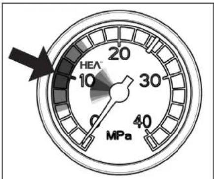
Set the low pressure in the HEA range and start.
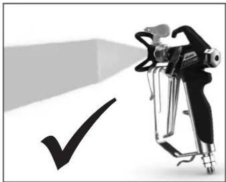
Even spray pattern without spray edges.
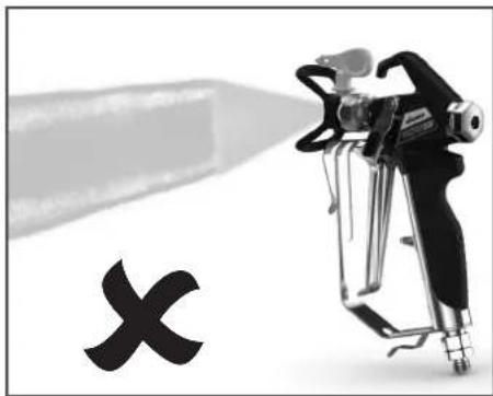
If edges are visible, slowly increase the pressure.
HEA tip table

All of the tips in the table below are supplied together with the appropriate gun fi lter.
| Application Tip marking Spray | angle | Bore inch / mm | Spraying width mm 1) | Gun filter Order no. | |
| Synthetic-resin paintsPVC paints | 211 | 20° | 0.011 / 0.28 | 120 | red0554211 |
| 311 | 30° | 0.011 / 0.28 | 150 | red0554311 | |
| 411 | 40° | 0.011 / 0.28 | 190 | Rot0554411 | |
| Paints, primersFillers | 213 | 20° | 0.013 / 0.33 | 120 | red0554213 |
| 313 | 30° | 0.013 / 0.33 | 150 | red0554313 | |
| 413 | 40° | 0.013 / 0.33 | 190 | red0554413 | |
| FillersRust protection paints | 415 | 40° | 0.015 / 0.38 | 190 | yellow0554415 |
| 515 | 50° | 0.015 / 0.38 | 225 | yellow0554515 | |
| 615 | 60° | 0.015 / 0.38 | 270 | yellow0554615 | |
| Rust protection paintsLatex paintsDispersions | 417 | 40° | 0.017 / 0.43 | 190 | white0554417 |
| 517 | 50° | 0.017 / 0.43 | 225 | white0554517 | |
| 617 | 60° | 0.017 / 0.43 | 270 | white0554617 | |
| Rust protection paintsLatex paintsDispersions | 519 | 50° | 0.019 / 0.48 | 225 | white0554519 |
| 619 | 60° | 0.019 / 0.48 | 270 | white0554619 | |
| Flame retardant 421 | 40° | 0.021 / 0.53 | 190 | white0554421 | |
| 521 | 50° | 0.021 / 0.53 | 225 | white0554521 | |
| 621 | 60° | 0.021 / 0.53 | 270 | white0554621 |
1) Spray width at about 30cm to the object and 100 bar (10 MPa) pressure with synthetic-resin paint 20 DIN seconds.
11.2 SPARE PARTS SF 21 PRO
| ITEM | ORDER NO. DESIGNATION |
| 1 245 | 2215 Inlet |
| 2 244 | 3908 Inlet valve housing assy. (incl. pos. 1) |
| 3 244 | 3943 Inlet valve |
| 4 244 | 3952 Fitting |
| 5 244 | 3941 Oil level measuring set |
| 6 244 | 3942 Fitting |
| 7 025 | 2776 Pressure gauge |
| 8 244 | 3921 Pressure relief valve assy. |
| 9 244 | 3904 Outlet valve |
| 10 243 | 38683 Label SF 21 Pro |
| 11 244 | 35241 Label (right+left) |
| 12 244 | 3944 Cover assy. |
| 13 244 | 3855 Rack cpl. |
| 14 244 | 4508 Screw set (4 pcs.) |
| 15 244 | 4509 Small parts set (incl. pos. 15a, 15b (2x), 15c, 15d (4x) |
| 16 244 | 3953 Cleaning cup |
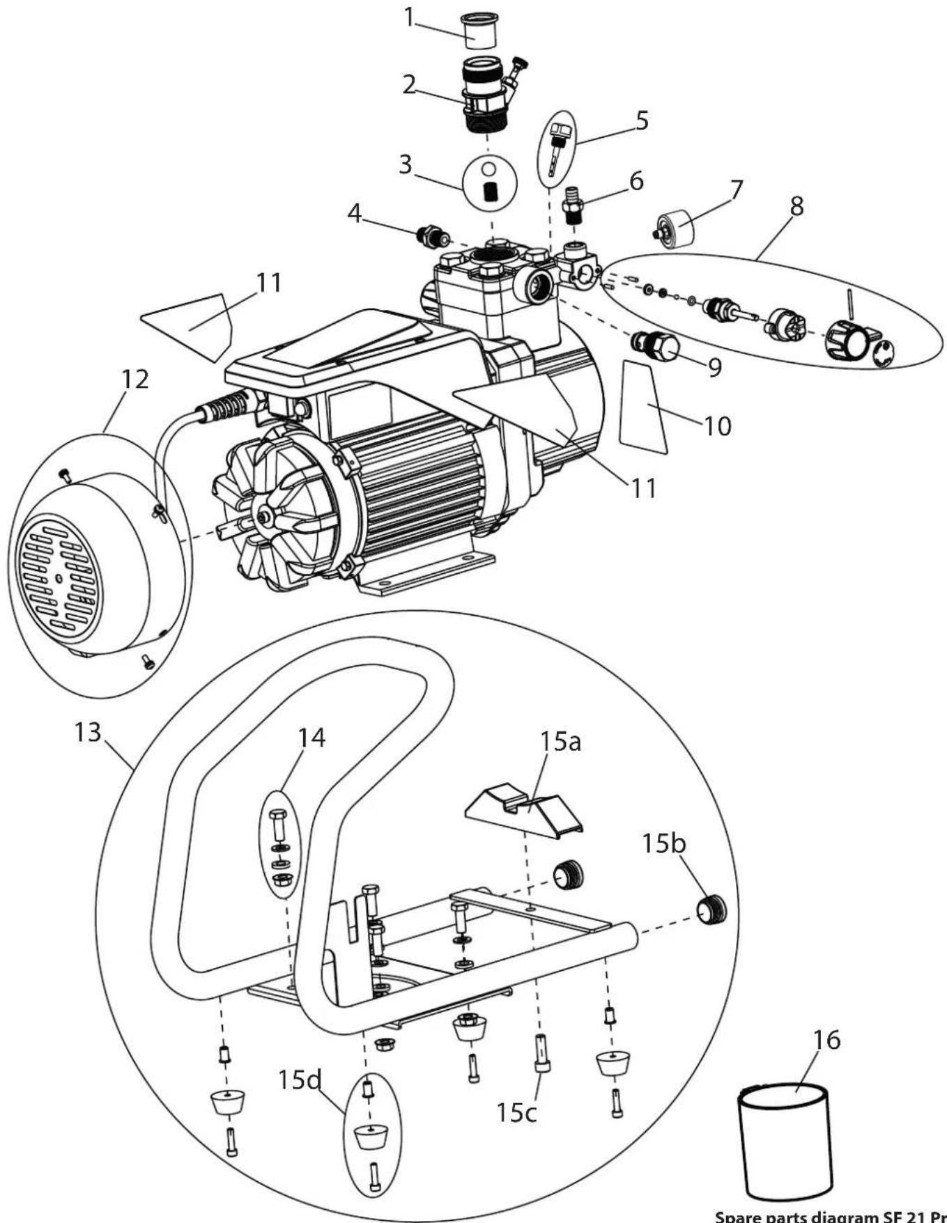
Spare parts diagram SF 21 Pro
11.3 SPARE PARTS LIST HIGH-PRESSURE FILTER
| ITEM | ORDER NO. DESIGN | |
| 1 0097 | 121 High-pressure filter HF-01 compl. | |
| 2 0097 | 301 Filter block | |
| 3 0097 | 302 Filter housing | |
| 4 0097 | 303 Hollow screw | |
| 5 0097 | 304 Seal ring | |
| 6 9970 | 110 Seal ring | |
| 7 9974 | 027 O-ring 30x2 (PTFE) | |
| 8 9971 | 401 O-ring 16x2 (PTFE) | |
| 9 0508 | 749 Bearing spring | |
| 10 0508 | 08 603 Bearing ring | |
| 11 | 0508 748 | Filter insert 60 meshes |
| Optional: | ||
| 0508 450 | Filter insert 100 meshes | |
| 0508 449 | Filter insert 30 meshes | |
| 12 9994 | 245 Pressure spring | |
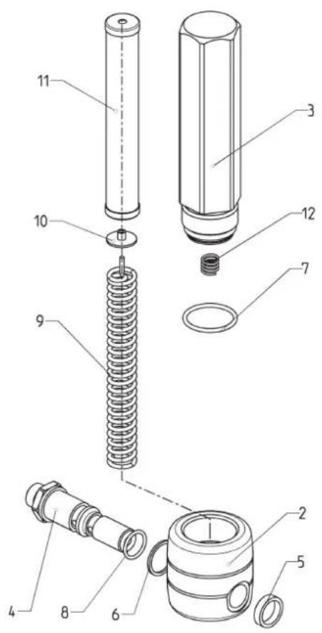
Spare parts diagram high-pressure filter
11.4 SPARE PARTS LIST HOPPER
| ITEM | ORDER NO. DESIGN | |
| 1 2444 | 212 Hopper 3 | 7 I, assy. (pos. 2-6) |
| 2 2445 | 295 Cover | |
| 3 9902 | 306 Sheet metal screw 3,9x13 (2) | |
| 4 0037 | 607 | Filter disk, mesh width 0,8 mm |
| 0003 756 | Optional: Filter disk, mesh width 0,4 mm | |
| 5 2445 | 298 Hopper | |
| 6 2445 | 297 Return pipe | |
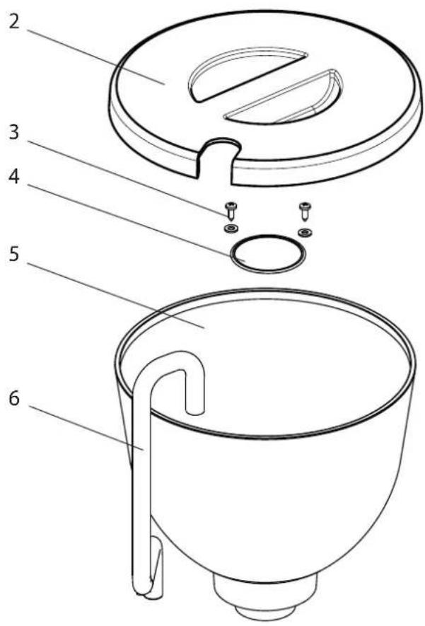
Spare parts diagram hopper
11.5 SPARE PARTS LIST SUCTION SYSTEM
| ITEM | ORDER NO. | DESIGNATION |
| 1 | 2444 | 4485 Suction system assay. |
| 2 | 2444 | 4491 Suction filter |
| 3 | 2444 | 4493 Return hose |
| 4 | 2444 | 4494 Clamp |
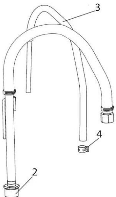
Spare parts diagram suction system
TESTING OF THE UNIT
For safety reasons, we would recommend having the device checked by an expert as required but at least every 12 months to ensure that it can continue to operate safely.
In the case of unused devices, the check can be postponed until they are next started up.
All (potentially deviating) national inspection and maintenance regulations must also be observed.
If you have any questions, please contact the customer service team at Wagner.
IMPORTANT INFORMATION ON PRODUCT LIABILITY
According to an EU directive, the manufacturer is only liable without limitation for faults in the product if all parts come from the manufacturer or have been approved by the manufacturer and have been mounted to the device and are operated properly. If third-party accessories or spare parts are used, the manufacturer is exonerated wholly or partly from his/her liability if use of the third-party accessories or spare parts have caused a defect in the product. In extreme cases, the relevant authorities can completely prohibit using the entire device.
With original WAGNER accessories and spare parts, compliance with all safety regulations is guaranteed.
NOTE ON DISPOSAL
In observance of the European Directive 2002/96/EC on waste electrical and electronic equipment and implementation in accordance with national law, this product is not to be disposed of together with household waste material but must be recycled in an environmentally friendly way!

Wagner or one of our dealers will take back your used Wagner waste electrical or electronic equipment and will dispose of it for you in an environmentally friendly way. Please ask your local Wagner service centre or dealer for details or contact us direct.
3 + 2 YEAR GUARANTEE ON THIS WAGNER CRAFTSMAN PRODUCT (Status 03.03.2022)
WAGNER exclusively provides the commercial buyer who has purchased the product from an authorised specialist dealer (hereinafter referred to as the "Customer") with a warranty for the products listed on the Internet at https://go.wagnergroup.com/3plus2-info in addition to the statutory warranty regulations, unless there is a warranty exclusion.
The warranty period for WAGNER products (devices) in the craftsmen's sector is 36 months and begins with the date of purchase of the initial purchase. This warranty period is extended by a further 24 months if the product is registered within
28 days of purchase on the Internet at https://go.wagnergroup.com/3plus2.
In cases of commercial rental, industrial use (e.g. use in shift operation) or equivalent use, the warranty period is 12 months due to the significantly higher load. We reserve the right to carry out a check in individual cases and refuse the warranty where necessary.
If any material, machining or performance defects are identified in the device within the warranty period, then the warranty claims must be made immediately and within a period of no more than 2 weeks following discovery of the defect.
The detailed guarantee conditions can be obtained on request from our authorised WAGNER partners (see website or operating instructions) or in text form on our website:
https://go.wagner-group.com/pf-warranty-conditions

Subject to modifications
EU Declaration of conformity
We declare under sole responsibility that this product conforms to the following relevant stipulations: 2006/42/EC, 2014/30/EU, 2011/65/EU, 2012/19/EU
Applied harmonised norms:
EN ISO 12100, EN 1953, EN 62841-1, EN IEC 55014-1, EN IEC 55014-2, EN IEC 61000-3-2, EN 61000-3-3
The EU declaration of conformity is enclosed with the product. If required, it can be re-ordered using order number 2448573.
UKCA Declaration of conformity
We declare under sole responsibility that this product conforms to the following relevant regulations:
Supply of Machinery (Safety) Regulations 2018
Electromagnetic Compatibility Regulations 2016
The Restriction of the Use of Certain Hazardous Substances in Electrical and Electronic Equipment Regulations 2012
The Waste Electrical and Electronic Equipment Regulations 2013
Applied harmonised standards
BS EN ISO 12100, BS EN 62841-1, BS EN 1953,
BS EN IEC 55014-1, BS EN IEC 55014-2, BS EN IEC 61000-3-2, BS EN 61000-3-3
INDICATION DE MISE AU REBUT
https://go.wagner-group.com/pf-warranty-conditions

10.1 VALVULA DE ADMISION
https://go.wagner-group.com/pf-warranty-conditions

B WSB Finishing Equipment
Veilinglaan 56-58
1861 Meise-Wolvertem
Belgium
Tel. +32/2/269 46 75
Telefax +32/2/269 7845
info@wagner-wsb.nl
NL WSB Finishing Equipment BV
De Heldinnenlaan 200,
3543 MB Utrecht
Netherlands
Tel. +31/ 30/241 4155
Telefax +31/ 30/241 1787
info@wagner-wsb.nl
CH Wagner International AG
Industriestrasse 22
9450 Altstätten
Schweiz
Tel. +41/71 / 7572211
Telefax +41 / 71 / 7 572222
wagner@wagner-group.ch
F J.Wagner France Sarl
Parc Work Center
S Orkla House Care AB,
Tallvagen 6
564 23 Bankeryd,
Sweden
Tel. +46 36 376300
Info@orkla.se
D J.WagnerGmbH
Wagner Spraytech (UK) Limited
Innovation Centre
Silverstone Park, Silverstone
Northants NN12 8GX
Great Britain
Tel. 01327 368410
enquiries@wagnerspraytech.co.uk
AUS Wagner Spraytech Australia Pty. Ltd.
8-10 Dansu Court
Hallam, Victoria, 3803
Australia
Customer Service 1800 924 637
info@wagneraustralia.com.au
RU Ummnoptep:
OOB «BnHTexpyc>
143960 MO, r. PeYToB, yUnca
Keene3HOpOxHa, 11, KB./oF.V
Telefoh: +7 (499) 705-11-31
Почта: hello@wagner.ru
CaiT: www.wagner.ru
N3ROTOBNTenb:
Дж. BarHep Гм6x,
OTTO-JIInHeTAn,18
Д-88677 MapKdopΦ, Германя
www.wagner-group.com


- REPARATUREN AM GERÄT 17
- EXPLOSIONSSCHUTZ
- REPARATUREN AM GERÄT
- PRÜFUNG DES GERÄTES
- Translation of the original operating instructions Contents
- GENERAL SAFETY INSTRUCTIONS 28
- SAFETY REGULATIONS FOR AIRLESS SPRAYING 30
- 3GENERALVIEWOFAPPLICATION/ DESCRIPTIONOFUNIT 33
- STARTUP 36
- SPRAYING TECHNOLOGY 38
- HANDLING THE HIGH-PRESSURE HOSE 39
- 7INTERRUPTIONOFWORK 39
- CLEANING THE UNIT 40
- SERVICING 42
- REPAIRS AT THE UNIT 43
- SPARE PARTS AND ACCESSORIES 46
- European service network 108
- GENERAL SAFETY INSTRUCTIONS
- Safety at the workplace
- Electrical Safety
- Safety of Persons
- Careful Handling and Use of Power Tools
- Service
- SAFETY REGULATIONS FOR AIRLESS SPRAYING
- FLASH POINT
- EXPLOSION PROTECTION
- DANGER OF EXPLOSION AND FIRE FROM SOURCES OF IGNITION DURING SPRAYING WORK
- DANGER OF INJURY FROM THE SPRAY JET
- RECOIL OF SPRAY GUN
- BREATHING EQUIPMENT AS PROTECTION AGAINST SOLVENT VAPORS
- PREVENTION OF OCCUPATIONAL ILLNESSES
- HIGH-PRESSURE HOSE
- ELECTROSTATIC CHARGING (FORMATION OF SPARKS OR FLAMES)
- USE OF UNITS ON BUILDING SITES AND WORKSHOPS
- VENTILATION WHEN SPRAYING IN ROOMS
- SUCTION INSTALLATIONS
- EARTHING OF THE OBJECT
- COATING MATERIAL
- CLEANING THE UNIT
- WORK OR REPAIRS AT THE ELECTRICAL EQUIPMENT
- MAINTENANCE WORK AND BREAKS
- SETUP ON AN UNEVEN SURFACE
- GENERAL VIEW OF APPLICATION/ DESCRIPTION OF UNIT
- APPLICATION
- COATING MATERIAL
- COATING MATERIALS WITH SHARP-EDGED ADDITIONAL MATERIALS
- FILTERING
- EXPLANATORY DIAGRAM
- TECHNICAL DATA
- Transportation in vehicle
- STARTUP
- UNIT WITH SUCTION SYSTEM
- UNIT WITH UPPER HOPPER
- HIGH PRESSURE HOSE AND SPRAY GUN
- CONNECTION TO THE MAINS NETWORK
- CLEANING PRESERVING AGENT WHEN STARTING-UP OF OPERATION INITIALLY
- Unit with suction tube
- Unit with hopper
- VENTILATE UNIT (HYDRAULIC SYSTEM) IF THE SOUND OF INLET VALVE IS NOT AUDIBLE
- TAKING THE UNIT INTO OPERATION WITH COATING MATERIAL
- SPRAYING TECHNIQUE
- HANDLING THE HIGH-PRESSURE HOSE
- INTERRUPTION OF WORK
- CLEANING THE UNIT
- - Unit with suction system
- - Unit with upper hopper
- CLEANING THE UNIT FROM THE OUTSIDE
- SUCTION FILTER
- suction system hopper
- HIGH-PRESSURE FILTER
- CLEANING THE AIRLESS SPRAY GUN
- Insertion filter in the Airless spray gun
- SERVICING
- GENERAL SERVICING
- Minimum check before every startup:
- Check at periodical intervals:
- HIGH-PRESSURE HOSE
- REPAIRS AT THE UNIT
- INLETVALVE
- Disassembly
- Installation
- OUTLETVALVE
- Please also pay particular attention to the following notes:
- PRESSURE CONTROL VALVE
- TYPICAL WEAR PARTS
- SPARE PARTS AND ACCESSORIES
- SUPER FINISH 21 PRO ACCESSORIES
- HEA NOZZLES FOR LOW-MIST SPRAYING AT LOW PRESSURE
- HEA tip table
- SPARE PARTS LIST HIGH-PRESSURE FILTER
- SPARE PARTS LIST HOPPER
- SPARE PARTS LIST SUCTION SYSTEM
- TESTING OF THE UNIT
- IMPORTANT INFORMATION ON PRODUCT LIABILITY
- NOTE ON DISPOSAL
- + 2 YEAR GUARANTEE ON THIS WAGNER CRAFTSMAN PRODUCT (Status 03.03.2022)
- EU Declaration of conformity
- UKCA Declaration of conformity
- INDICATION DE MISE AU REBUT
- VALVULA DE ADMISION
Brand : WAGNER
Model : SuperFinish 21 Pro
Category : Paint spray